Parsun F4/F5 Outboard Engine Service Manual
Table of Contents
- General Information
- Specifications
- Periodic Service
- Recoil Starter
- Ignition System
- Fuel System
- Power Unit
- Upper Unit
- Lower Unit
General Information
Identification
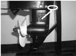
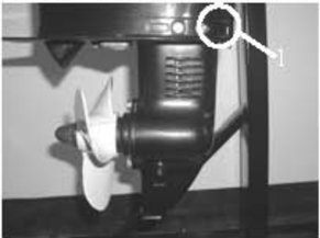
The outboard motor serial number is marked on the label.The label can be found on the bracket left assembly or on the upper part ofthe bracket swivel.Record your outboard motor serial number in the spaces provided to assist you in ordering spare parts from yourParsun dealer or for reference in case your outb oard motoris stolen.
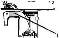
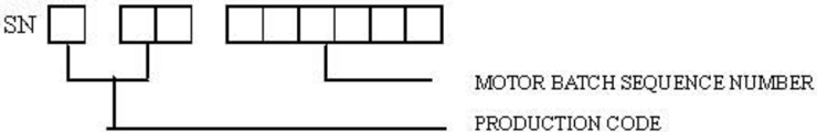
- 1.Outboardmotorserialnumberlocation Serial number as follows:
PRODUCTION CODE

Propeller Selection
The performance of your outboard motor will be critically affected by your choice of propeller, as an incorrect choice could adversely affect performance.
For a greater boat load and a low engine speed, a smaller-pitch propeller is more suitable. correct engine speed to be maintained.
When the engine is running at full throttle position, the suitable propeller should be used according performance.
| Propeller sizes | Material |
|---|---|
| 71/4x8 | Aluminum alloy |
| 71/2x7 | Aluminum alloy |
| 71/4×61/2 | Aluminum alloy |
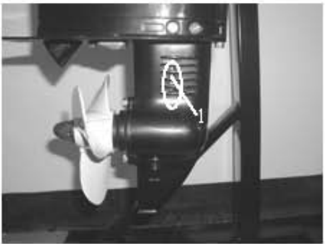
Emergency Start
Ifthe starting device isnot working,the engine can be started by emergency start cable. /WARNING:
- The start program can only be used in emergency and to return to harbor for repairing.
- not working. So please ensure the shift rod is in NEUTRAL position.
- Please ensure nobody standing behind you in case the cable is pulled out to hurt people.
- After the engine starts up,don't fit the start device or top cowling.Put clothing or other
- When starting and operating, don't touch ignition coil, spark plug cap or other electric
The procedure is as follows:
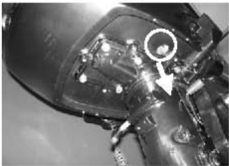
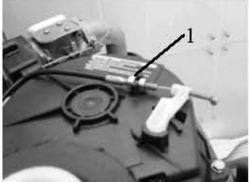
- 1.Remove the top cowling.
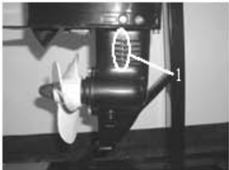
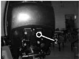
- 2.Remove the start-in-gear protection device cable,and remove the chock lever cable.
- 1.Start-in-gear protection device cable
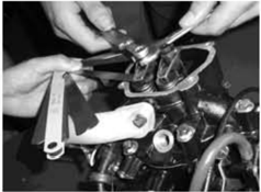
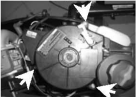
- 3.Demount threebolts and remove starter.
- 4.Assembletwobolts to fixthefuel tank.
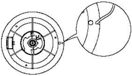
- 5.Insert the knot of the cable in the notch of flywheel rotor, and wind the cable around flywheel severalroundsin clockwisedirection.
- Pullthemanual starter.
- 2.Chock lever cable
- Give a strong pull to start the engine. Repeat if necessary.
Safety While Working
To prevent the danger or accidents when performing maintenance and repair, and improve the work efficiency, please obey the following safety procedures.
1. Fire Prevention
Gasoline (petrol), lubricant and grease are highly flammable.While working,keep away from heat, sparks and open flames.
2. Ventilation
Petroleum vapor and engine exhaust gases are violent in toxicity.They are harmful to breathe and deadly if inhaled in large quantities. When test-running an engine indoors, maintain good ventilation.
3. Self-Protection
Protect your eyes with suitable safety glasses or safety goggles, when drilling, grinding or operating air compressor. Protect hands and feet by wearing protective work clothes, safety gloves and shoes if necessary.
4. Lubricants and Sealing Fluids
When performing maintenance procedures and repair to Parsun outboards, use only products provided or recommended by our Company.
Undernormalconditionsofuse,thereshouldbenohazardsfromtheuseofthelubricants mentioned in this manual, but safety is all-important, and by adopting good safety practices, any risk is minimized.
A summary of the most important precautions is as follows:
- ① To protect the skin, the application of a suitable barrier cream to the hands before working is recommended.
- Clothingwhich hasbecome contaminatedwith lubricants should be changed as soon as practicable, and washed before further use.
- ③ Avoidskincontactwithlubricants.
- ① Hands and any other part of the body which have been in contact with lubricants or lubricant-contaminatedclothing,should bethoroughlywashedwithhotwater andsoap as soon as practicable.
- A supply of clean lint-free cloths should be available for wiping run-off lubricants or grease.
5. Good Working Practices
- ① Follow the tightening torque instruction. When tightening bolts, nuts and screws, tighten the large sizes first, and tighten inner-positioned fixings before outer-positioned ones.
- O Use the recommended special tools to protect parts from damage.Use the right tool in the right manner.
Disassembly and Assembly
When disassembly and assembly, please follow the following principles:
- 1.Use specialtools when disassermbling and assembling.
- Clean dirt before disassemb ling the parts.
- 3.Oil the contact surfaces of mov ing parts before assermbly.
- Install bearing with the manufacburer's markings on the side exposed to view and liberally oil the bearing.
- 5.When installing oil seals, apply a light coating of water-resistant grease to the ledge and outside diarmeter.
One-Time Use Parts
One-time use parts are gasket, oil seal, O-ring, cotter pin and spring, ring, and etc. When re-assemb ling outb oard engine, you must change the one-time use parts.
Pre-Delivery Check
To ensure the using, please inspect the following before delivery.
1. Checking Fuel System
Check ifthe fuel pipe is connected firmly, and if the fuel is filled with fuel.
CAUTION: Do not use pre-mixed fuel for this 4 stoke outb oard engine.
2. Checking Oil Level
- Check the engine oil level
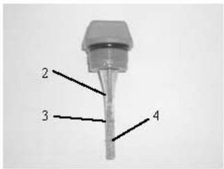
Remove oil cap, check engine oil level.
- Oil cap 2. Oil rule 3. High position mark 4. Low position mark
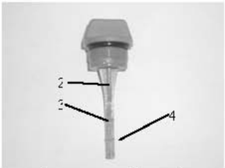
oil; if below lower mark, add engine oil up to upper level.
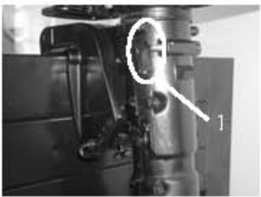
Check the gear oil level:
Remove the oil level plug.Check if the gear oil overflows at the oil level checking hole. If so, install the oil level plug and tighten it according to specified torque. Otherwise please add gear oil.
1.Oil level plug
- 3. Check Steering System: Check if steering is stable. Check if steering friction is adjusted correctly. Turn clamp handle screw clockwise to increase resistance. Turn clamp handle screw counter clockwise to lower resistance. 4. Check Shift Lever and Throttle: Check if the shift lever is operated smoothly.
Checkif the throttle grip is turned smoothly from full closed position to full open position.
5. Check Engine Stop Switch Assembly: Check stopper hang rope.
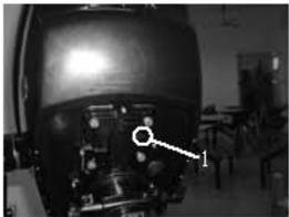
6. Check Cooling Water Checking Hole
When the engine is running, check if cooling water overflows at the cooling water checking hole.
1.Cooling water checking hole
7. Breaking-In Running
- ① Initial 1 hour: operate the engine at 2000 r/min or about a half throttle.
- ② The second hour: operate the engine at 3000 r/min or about 3/4 throttle.
- ? The following 8hours: operate the engine at fullthrottle continuously.Each operation time doesn't exceed 5 minutes.
8. Inspection After Breaking-In Running
- Check if gear oil contains water.
- ② Check if the fuel line leaks.
- After breaking-in running, operate the engine at idling speed.Use cleaning tool to wash
- Clamp handle screw
over the coolingwater passage by fresh water.
- After breaking-in running, inspect idling speed.
- Preheating engine for 5 minutes.
- 2 Using the tachometer to measure idling speed RPM. If out of specification, adjust it. Idling speed: 1450~1550 r/min
- Turm the throttle stop screw clockwise or counter clockwise until the specified idling speed is attained.
- After adjusting idling speed, picking up RPM several times to check the engine's stability.
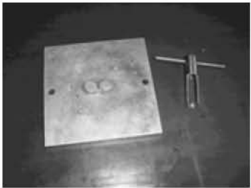
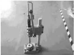
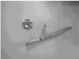
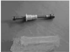
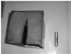
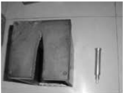
Special Tools and Detection Device
When performing maintenance and repair, you need to use all kinds of special tools and detection device.The use of correct tools will improve the work efficiency and avoid of the damage to the people and outboard engines.
Special Tools
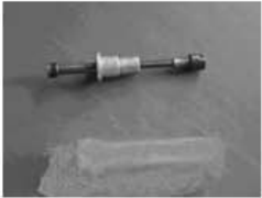
Piston slider
Valve spring compressor
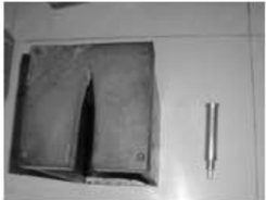
Oil seal installer tool
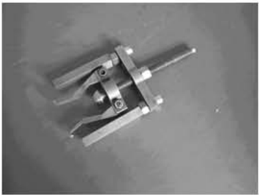
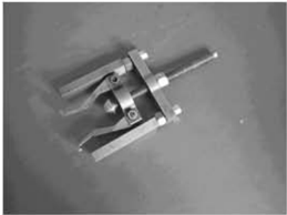
Flywheel holder and puller
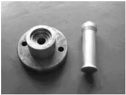
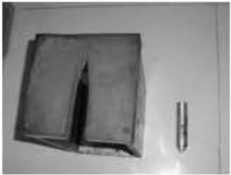
Housingbearing installer
Housing oil seal installer
Bearing puller
Lower casing cover bearing installer
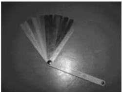
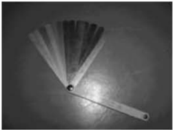
Space gage
Barrel bearing with guard boardinstaller tool
Lower casing bracket and barrel bearing without guard boardinstaller tool
Lower casing bracket and drive shaft oil seal installer tool
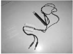
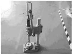
Detection Device
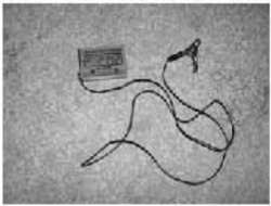
Digital tachometer
Digital circuit tester
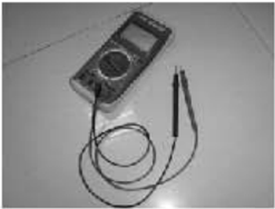
Peak voltage adaptor
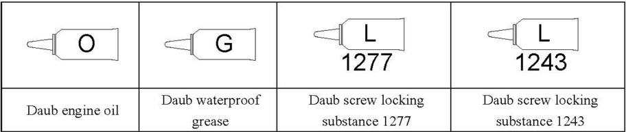
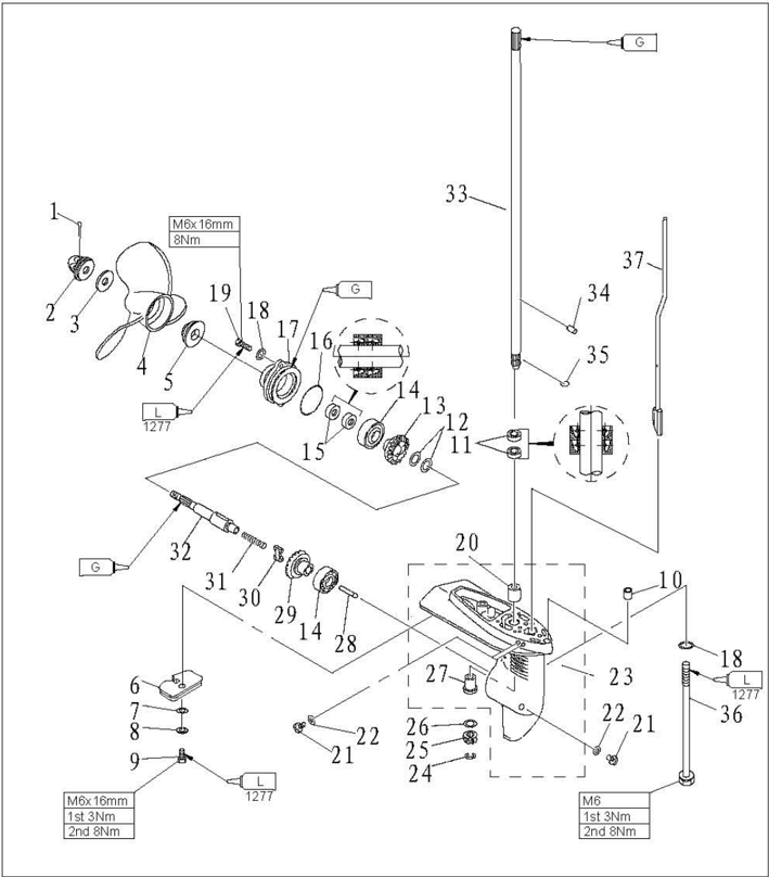
Explosive Drawing and Symbol
Explosive Drawing
- 1 Parts explosive drawing
- Oil, fluid sealant or locking substance daubing point
- Screw specification and specified torque
- Spare parts details
Symbol
Specifications
Outboard Engine Specifications
| Category | Specification | Value |
|---|---|---|
| Dimension | Overall length | 717mm |
| Dimension | Overall width | 361mm |
| Dimension | Overall height (S) | 1029mm |
| Dimension | Overall height (L) | 1156mm |
| Weight | S | 24.5kg |
| Weight | L | 25.5kg |
| Performance | Max output | 2.9kW (4hp) @ 4500 r/min; 3.6kW (5hp) @ 5000 r/min |
| Performance | Full throttle operation | 4000~5000 r/min |
| Performance | Max fuel consumption | 1.6 L/h @ 5000 r/min |
| Performance | Idle speed (Neutral) | 1500±50 r/min |
| Power Unit | Type | 4 stroke, OHV |
| Power Unit | Number of cylinders | 1 |
| Power Unit | Displacement | 112 cm³ |
| Power Unit | Bore × Stroke | 59mm × 41mm |
| Power Unit | Compression ratio | 8.4 |
| Power Unit | Compression pressure | 660 kPa |
| Power Unit | Number of carburetor | 1 |
| Power Unit | Control system | Tiller control |
| Power Unit | Starting system | Recoil starter |
| Power Unit | Ignition control system | T.C.I |
| Power Unit | Starting enrichment | Choke valve |
| Power Unit | Spark plug | BPR7HS |
| Power Unit | Exhaust system | Under water |
| Power Unit | Lubrication system | Splash lubrication |
| Fuel and Oil | Fuel type | Unleaded regular gasoline |
| Fuel and Oil | Fuel standard | PON 86, RON 91 |
| Fuel and Oil | Fuel tank capacity | 1.3L |
| Fuel and Oil | Recommended engine oil | API SE, SF, SE-SF, SG-CD SAE 10W30, 10W40 |
| Fuel and Oil | Engine oil quantity | 0.5L |
| Fuel and Oil | Recommended gear oil | Hypoid gear oil SAE #90 |
| Fuel and Oil | Gear oil quantity | 100 mm³ |
| Bracket | Tilt angle | 4°, 8°, 12°, 16°, 20° |
| Bracket | Tilt-up angle | 76° |
| Bracket | Shallow water cruising angle | 30°, 42°, 54° |
| Bracket | Steering angle | 360° |
| Drive Unit | Gear positions | F-N-R |
| Drive Unit | Gear ratio | 2.08 |
| Drive Unit | Gear type | Bevel gear |
| Drive Unit | Propeller direction | Clockwise |
| Drive Unit | Propeller drive system | Spline |
Maintenance Information
Power Unit
| Item | Specification | Detail | Value |
|---|---|---|---|
| Cylinder Head | Warp limit | 0.1mm | |
| Cylinder | Bore | 59.00~59.02mm | |
| Cylinder | Wear limit | 59.1mm | |
| Cylinder | Taper limit | 0.08mm | |
| Cylinder | Out of round limit | 0.05mm | |
| Piston | Piston diameter | 58.950~58.965mm | |
| Piston | Measuring point height | 10mm (from the bottom of piston) | |
| Piston | Piston-to-cylinder clearance | 0.035~0.065mm | |
| Piston | Pin boss inside diameter | 13.009~13.017mm | |
| Piston pin | Outside diameter | 12.995~13.000mm | |
| Piston ring (Top) | Thickness | 1.5mm | |
| Piston ring (Top) | Breadth | 2.6mm | |
| Piston ring (Top) | End gap | 0.10~0.20mm | |
| Piston ring (Top) | Wear limit | 0.40mm | |
| Piston ring (Top) | Side clearance | 0.04~0.08mm | |
| Piston ring (2nd) | Thickness | 1.5mm | |
| Piston ring (2nd) | Breadth | 2.6mm | |
| Piston ring (2nd) | End gap | 0.25~0.40mm | |
| Piston ring (2nd) | Wear limit | 0.60mm | |
| Piston ring (2nd) | Side clearance | 0.02~0.06mm | |
| Piston ring (Oil) | Thickness | 2.5mm | |
| Piston ring (Oil) | Breadth | 2.6mm | |
| Piston ring (Oil) | End gap | 0.20~0.70mm | |
| Piston ring (Oil) | Wear limit | 0.90mm | |
| Valve | Valve clearance (cold) | Intake | 0.10±0.02mm |
| Valve | Valve clearance (cold) | Exhaust | 0.10±0.02mm |
| Valve | Face width | Intake | 1.84~2.26mm |
| Valve | Face width | Exhaust | 1.84~2.26mm |
| Valve | Seat width | Intake | 0.6~0.8mm |
| Valve | Seat width | Exhaust | 0.6~0.8mm |
| Valve | Margin | Intake | 0.7mm |
| Valve | Margin | Exhaust | 1.0mm |
| Valve | Head diameter | Intake | 23.9~24.1mm |
| Valve | Head diameter | Exhaust | 21.9~22.1mm |
| Valve | Stem outside diameter | Intake | 5.475~5.490mm |
| Valve | Stem outside diameter | Exhaust | 5.460~5.475mm |
| Valve | Guide inside diameter | Intake | 5.500~5.512mm |
| Valve | Stem-to-guide clearance | Intake | 0.010~0.037mm |
| Valve | Stem-to-guide clearance | Exhaust | 0.025~0.052mm |
| Push rod | Runout limit | 0.5mm | |
| Valve spring | Free length | 35.0mm | |
| Valve spring | Free length limit | 34.0mm | |
| Connecting rod | Tilt limit | 1.2mm | |
| Connecting rod | Small end inside diameter | 13.006~13.02mm | |
| Connecting rod | Big end oil clearance | 0.016~0.046mm | |
| Crankshaft | Crankshaft width | 64.4~64.5mm | |
| Crankshaft | Big end side clearance | 0.2~0.6mm | |
| Crankshaft | Round limit | 0.03mm |
Continued:
| Item | Specification | Detail | Value |
|---|---|---|---|
| Camshaft | Lobe height | Intake | 26.736~26.836mm |
| Camshaft | Lobe height | Exhaust | 26.532~26.623mm |
| Camshaft | Round diameter | 21.950~22.050mm | |
| Camshaft | Journal diameter | 14.966~14.984mm | |
| Camshaft | Camshaft round limit | 0.03mm | |
| Valve lifter | Outside diameter | 7.978~7.987mm | |
| Thermostat | Valve opening temperature | 58~62℃ | |
| Thermostat | Full-open temperature | 70℃ | |
| Thermostat | Valve lift | 3mm | |
| Fuel pump | Discharge | 8 L/h | |
| Fuel pump | Pressure | 50 kPa | |
| Fuel pump | Plunger stroke | 1.8~2.2mm |
Ignition system
| Item | Description |
|---|---|
| Ignition timing | BTDC 28°~32° |
| T.C.I system output peak voltage | 130V |
| T.C.I air gap | 0.4~0.6mm |
| Spark plug gap | 0.6~0.7mm |
| Ignitor ass'y resistance (Primary coil) | 0.7~0.96Ω |
| Ignitor ass'y resistance (Secondary coil) | 5.8~7.0KΩ |
Tightening Torque
Specified torque
| Part to be tightened | Detail | Part name | Thread size | Quantity | Torque |
|---|---|---|---|---|---|
| Oil drain | Bolt | M8 | 1 | 20 Nm | |
| Spark plug | — | M14 | 1 | 25 Nm | |
| Recoil starter | Bolt | M6 | 3 | 8 Nm | |
| Flywheel rotor ass'y | Nut | M10 | 1 | 44 Nm | |
| Carburetor | Bolt | M6 | 2 | 8 Nm | |
| Intake manifold | Bolt | M6 | 2 | 8 Nm | |
| Cylinder head cover | Bolt | M6 | 4 | 11 Nm | |
| Cylinder head | 1st tightening | Bolt | M8 | 4 | 15 Nm |
| Cylinder head | 2nd tightening | Bolt | M8 | 4 | 30 Nm |
| 1st tightening | Bolt | M6 | 1 | 6 Nm | |
| 2nd tightening | Bolt | M6 | 1 | 11 Nm | |
| Rocker arm screw bolt | Bolt | M6 | 2 | 10 Nm | |
| Locknut (rocker arm) | Nut | M6×0.75 | 2 | 10 Nm | |
| Oil seal housing | Bolt | M8 | 1 | 18 Nm | |
| Power unit mounting | Bolt | M6 | 7 | 8 Nm | |
| Thermostat cover | Bolt | M6 | 3 | 8 Nm | |
| Breather cover | Bolt | M6 | 3 | 8 Nm | |
| Crankcase | 1st tightening | Bolt | M8 | 7 | 10 Nm |
| Crankcase | 2nd tightening | 7 | 22 Nm |
Cont'd
| Part to be tightened | Detail | Part name | Thread size | Quantity | Torque |
|---|---|---|---|---|---|
| Connecting rod | Bolt | M7 | 2 | 12 Nm | |
| Oil splash gear unit | Bolt | M6 | 1 | 8 Nm | |
| Lower unit mounting | 1st tightening | Bolt | M6 | 2 | 3 Nm |
| Lower unit mounting | 2nd tightening | Bolt | M6 | 2 | 8 Nm |
| Lower unit housing cover | 1st tightening | Bolt | M6 | 2 | 6 Nm |
| Lower unit housing cover | 2nd tightening | Bolt | M6 | 2 | 11 Nm |
| Anode | 1st tightening | Bolt | M6 | 1 | 3 Nm |
| Anode | 2nd tightening | Bolt | M6 | 1 | 8 Nm |
| Water pump housing | 1st tightening | Bolt | M6 | 4 | 3 Nm |
| Water pump housing | 2nd tightening | Bolt | M6 | 4 | 8 Nm |
| Water pump base | 1st tightening | Bolt | M6 | 1 | 3 Nm |
| Water pump base | 2nd tightening | Bolt | M6 | 1 | 8 Nm |
| Steering handle mounting | Bolt | M8 | 1 | 18 Nm | |
| Shift lever bracket | Bolt | M6 | 1 | 4.5 Nm | |
| Bracket fixed cover | 1st tightening | Bolt | M6 | 2 | 3 Nm |
| Bracket fixed cover | 2nd tightening | Bolt | M6 | 2 | 8 Nm |
| Tilt lock plate | 1st tightening | Nut | M6 | 2 | 3 Nm |
| Tilt lock plate | 2nd tightening | Nut | M6 | 2 | 8 Nm |
| Swivel bracket | 1st tightening | Nut | M6 | 6 | 3 Nm |
| Swivel bracket | 2nd tightening | Nut | M6 | 6 | 8 Nm |
| Clamp bracket | Nut | M8 | 1 | 13 Nm | |
| Ignitor ass'y | Bolt | M6 | 2 | 8 Nm |
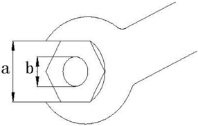
General torque
| Nut (a) | Bolt (b) | Torque |
|---|---|---|
| 8mm | M5 | 5Nm |
| 10mm | M6 | 8 Nm |
| 12mm | M8 | 18 Nm |
| 14mm | M10 | 36 Nm |
| 17mm | M12 | 43 Nm |
Periodic Service
Maintenance Timetable
| Items | Contents | 10 hours (1 month) | 50 hours (3 months) | 100 hours (6 months) | 200 hours (1 year) |
|---|---|---|---|---|---|
| Anode | Inspection/replacement | O | O | ||
| Spark plug | Cleaning/adjustment/replacement | O | O | O | |
| Grease points | Greasing | O | |||
| Bolts and nuts | Inspection | O | O | ||
| Fuel tank and fuel line | Inspection | O | |||
| Fuel filter | Inspection/replacement | O | O | O | |
| Fuel cock | Inspection/replacement | O | O | ||
| Carburetor | Inspection/replacement | O | O | ||
| Throttle cable | Inspection/replacement | O | O | ||
| Idling speed | Inspection/adjustment | O | O | ||
| Start-in-gear protection | Inspection/adjustment | O | O | ||
| Engine oil | Replacement | O | O | ||
| Valve clearance | Inspection/adjustment | O | O | ||
| Ignition timing | Inspection | O | O | ||
| T.C.I air gap | Inspection/adjustment | O | O | ||
| Thermostat | Inspection | O | |||
| Cooling water passage | Inspection/Cleaning | O | O | ||
| Gear oil | Replacement | O | O | ||
| Water pump | Inspection | O | |||
| Propeller | Inspection/replacement | O | O |
CAUTION: After running the outboard engine in saltwater,wastewater or mudwater,wash overthe enginebyfreshwaterimmediately.
If using leadedgasoline frequently,check thevalve and components each 100 hours.
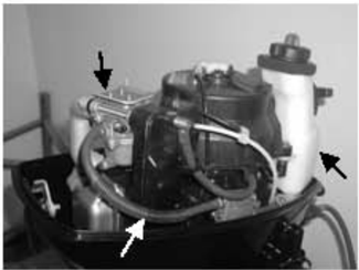
Fuel System (Periodic)
- Check fuel tank,CARBURETOR,FUEL Check if fuel tank, carburetor, fuel pump and fuel pipe are damaged or leaked. Replace if necessary.
Check if the fuel filter on the tank is dirty.Clean dirt or replace it if necessary.
2. Check Fuel Cock and Fuel Joint: Check if fuel cock and fuel joint are cracked, damaged or leaking.
Replace if necessary.
3. Check Fuel Filter: Check if fuel filter is cracked,damaged or has dirt inside. If so,replace it.
CAUTION: The arrow mark of the fuel filter must face toward the fuel pump. Clean the spilled oil.
Power Unit (Periodic)
Engine oil level
- a)Remove oil levelplug,check engine oil level,ifbetween the following marks of theupper and lower.
- Oil level plug2. Oil rule3. High position mark 4. Lowposition mark
- b) If above the upper mark, drain the engine oil, if below lower mark, add engine oil up to upper mark.
CAUTION: Run the engine and then turn it off, wait for several minutes, and check the engine oil level by the oil rule again.
If the engine oil still notwithin the proper level, add/drain as needed.
Changing engine oil
- 1.Remove oil level plug, drain plug with washer and gasket,drain off the engine oil.
- Install new gasket and washer, install drain plug.
- 3.Fill engine oil into the crankcase through oil filler hole. Engine oil quantity: 0.5L Oil type:API SE,SF,SE-SF,SG-CD SAE 10W30,10W40
- Install oil level plug.
- 5.Check engine oillevel.
CAUTION: Rotate the flywheel clockwise so that rocker arm is in free position, before adjusting valve clearance (Dead point position on compression stroke).
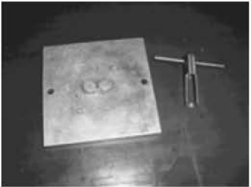
Valve clearance
- 2.Remove cylinder head cover
- Use feeler gauge to measure the clearance between rocker arm and valve rod top: if out of specification, adjust.
- Remove spark plug cap and spark plug.
Valve clearance (cold position):
Inlet valve:0.10±0.02mm
Outlet valve: 0.10±0.02mm
Spark plug
- 2.Clean off carbon build-up on the electrodes.
- 3.Check if the electrodes are corroded or have deposit, or if the washer is damaged. If necessary, change the spark plug. Spark plug type: BPR7HS
- Inspect if the spark plug gap is within specification. If necessary, change the spark plug.
- Install spark plug. Use spark plug spanner to tighten it according to specified torque. Specified torque: 25 Nm
Control System
Throttle grip
- 1.Turn the throttle grip to fully closed position.
- 2.Check if the throttle cable is slack and if the throttle lever touches the throttle stop screw.
- Loosen throttle cable stopper screw, adjust throttle cable position, and tighten throttle cable stop screw.
1.throttle cable stop screw

Idling speed
Check idling speed, and adjust it if necessary.
- 1.Preheat engine for 5 minutes.
- 2.Attach the tachometer to the spark plug wire to measure idling speed RPM.If out of specification, adjust it.
- 3.Turn the throttle stop screw clockwise or counter clockwise, until the specified idling speed is attained.
Idling speed:1450~1550 r/min
NOTE: Turning clockwise to increase idling speed.
Turning counter clockwise to decrease idling speed.
CAUTION:
Start-in-gear protection
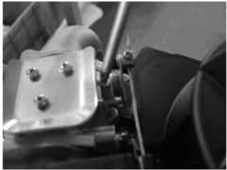
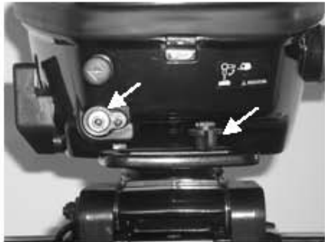
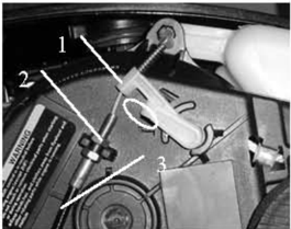
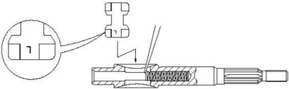
Set the shift lever in neutral, and check if the triangle marking of the detent aligns with the triangle marking of the starter.If necessary, adjust the adjusting nut on the tightw ire of the detent.
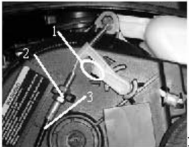
- Triangle marking 2. Adjusting nut 3. Tightwire ass'y, detent
Check gear oil level
Remove the oil level plug.If the gear oil overflows at the oil level checking hole, the oil volume added is correct; otherwise please add gear oil.
1.Oil level plug
Lower Unit (Periodic)
Changing gear oil
- 1.Hold the outboard engine in an upright position.
- 2.Place a containerunder the drain plug.
- 3.Remove the drain plug,the oil level plug, and then drain the gear oil.
- 4.Add gear oil through the drain plug using pressure filling device.
- When gearoil overflows at theoillevel checkinghole,nstall theoillevel lug 5.
- 6.Install the drain plug, then clean overflowing gear oil.
1.Oil level plug 2.Drain plug
NOTE: Check the drained gear oil.
Ifthe gear oil is millky, please check the oil seal. If necessary, replace the oil seal.
CAUTION: Must change drain plug washer each time.
- 1.Inspect cooling water passage Ifblocked,clean it
Lower unit leakage check
Connecting the leakage tester to the oil level checking hole to check the lower unit leakage.If the pressure drops (pressure: 1kg/cm?), inspect the oil seal and comp onents.
General Inspection
Anode
Inspect lower unit anode and engine anode(on the therrmostat cover).Clean the greasy dirt and scales.If wear or damage is above 1/2,replace the anode.
CAUTION: Cannot grease or pa int the anode, or it will not operate properly.
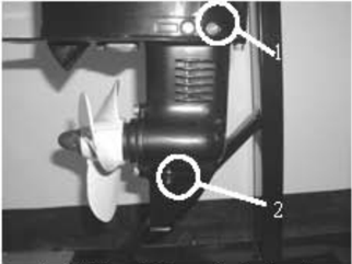
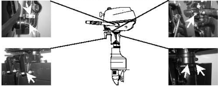
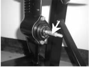
Grease points
- 1.Referthe illustration for greasing points, paint the water resistant grease.
- 2.Paint anti-corrosion grease on the propeller shaft.
Cooling Water Passage
Cooling water passage inlet
- 2.Place the outboard engine in the water and ensure the water level is above the anti-vortex plate, then start the engine.
- 3.Check if water overflows at the cooling water checking hole.If there is noflow or intermittent flow,check thecoolingwaterpassage.
1.Cooling water inlet
- Cooling water checking hole
Recoil Starter
NOTICE: When you service, please wear safety glasses and gloves.Please rermove spark plug cap and
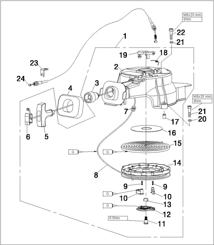
Explosive Drawing

| SN. | Part No. | Description | QTY | Remarks |
|---|---|---|---|---|
| 1 | F4-04130000 | STARTER ASSY | 1 | |
| 2 | F4-04130001 | CASE, STARTER | 1 | |
| 3 | F4-04130012 | GUIDE, ROPE | 1 | |
| 4 | F4-04130018 | SEAL, RUBBER | 1 | |
| 5 | F4-04130101 | HANDLE, STARTER | 1 | |
| 6 | F4-04130102 | COVER | 1 | |
| 7 | F4-04130013 | MEATUS, START ROPE | 1 | |
| 8 | F4-04130011 | WIRE, STARTER | 1 | |
| 9 | F4-04130004 | SPRING, DRIVE | 2 | |
| 10 | F4-04130003 | PAWL, DRIVE | 2 |

| SN. | Part No. | Description | QTY | Remarks |
|---|---|---|---|---|
| 11 | F4-04130008 | BOLT, STARTER | 1 | |
| 12 | F4-04130006 | PLATE, PRELL | 1 | |
| 13 | F4-04130007 | SPRING, PLATE | 1 | |
| 14 | F4-04130019 | DRUM, SHEAVE | 1 | |
| 15 | F4-04130005 | SPRING, VOLUTE | 1 | |
| 16 | F4-04130014 | WASHER, THRUST | 1 | |
| 17 | F4-04130002 | BUSHING, STARTER CASING | 1 | |
| 18 | F4-04130010 | WREST SPRING, DETENT | 1 | |
| 19 | F4-04130009 | DETENT | 1 | |
| 20 | GB/T97.1-85 | WASHER, THRUST | 3 |
| SN. | Part No. | Description | QTY | Remarks |
|---|---|---|---|---|
| 21 | GB/T5783-2000 | BOLT, HEXAGON M6×35 | 2 | |
| 22 | GB/T5783-2000 | BOLT, HEXAGON M6×20 | 1 | |
| 23 | F4-04000005 | FIXED PLATE, TIGHTWIRE | 1 | |
| 24 | F4-02000013 | TIGHTWIRE ASSY, DETENT | 1 |
- Open the top cowling
- 2.Screw loosely the adjusting nut of the dent tightwire.
- 3.Remove thetightwirefrom thedetent.
- 4.Remove the starter fixing bolt, and remove the starter.
- Adjusting nut
Starter Rope Replacement
- Pull the starter rope out, and insert it in the notch of the sheave drum.T Turn the sheave drum clockwise until the volute spring is free.
- 2.Pull the starter rope completely.
- Remove the starter handle cover from the starter handle, and remove the starter rope. Untie the knot at the end of the starter rope.
- 4.Pull out the starter rope completely.
- 5.Insert the new starter rope into the starter assembly, and fix the rope onto the sheave drum and starter handle. At the end of the rope tie a knot as shown.
Disassembling

- Insert the start rope in the notch of the sheave drum and turn the sheave drum several rounds in counterclockwisedirection.
- Pull the starter handle many times to check if the sheave drum rotates stably. If necessary, repeat step 6 and step 7.
Disassembling and Inspection (Starter)
- Remove the start rope.
- Remove starter bolt, and remove press plate.
- Remove the sheave drum
WARNING: Uninstall the sheave drum carefully, to ensure that the volute spring does not pop out to hurt people.
- 4.Remove the volute spring.
- Remove the detent and detent wrest spring.
- Inspect if the detent is cracked, worn or damaged. If necessary, replace it.
- Check if the drive pawl is cracked, worn or damaged. If necessary, replace it.
- Inspect if the drive spring is broken, cranked or damaged. If necessary, replace it.
- Check if the volute spring is broken, cranked or damaged. If necessary, replace it.

Reverse the steps of disassembling.
- 1.Put starter onto the power unit.
- 2.Screw the hexagon bolt, and tighten it according to the specified torque.
- 3.Install the detent tightwire.
- Adjust the adjustingnuton thetightwireof thedent,and align the trianglemarking of the dent with the triarigle marking of the starter case.
- Triangle mark
- 2.Adjusting nut
- 3.Detent tightwire
Assembling and Installation (Starter)
Ignition System
NOTICE: When checking and repairing the ignition system, keep your hand, clothes, hair or personal belongings away from the rotating flywheel.
Check ignition coil on insulated working table, to prevent electricity leak and electroshock.
Don't touch the ignition coil or spark plug when the engine is running, to avoid electroshock. Keep the wires away from the rotating flywheel,to prevent the wire frombeing cut,or theinsulatinglayer of the wire from being worn.
When replacing fixing parts such as nuts and bolts, only parts from original manufacturer or parts made of same material and with strength can be used.Parts must be tightened according to the specified torques.
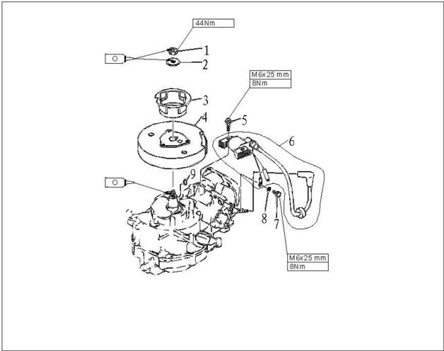
Explosive Drawing
| SN. | Part No. | Description | Remarks |
|---|---|---|---|
| 1 | GB/T6171-86 | NUT, HEXAGON M10×1.25 | |
| 2 | F4-04000021 | WASHER | |
| 3 | F4-04000020 | PULLEY, STARTER | |
| 4 | F4-04100000 | FLYWHEEL | |
| 5 | GB/T5782-2000 | BOLT M6×25 | |
| 6 | F4-04000038 | IGNITION WINDING ASSY | |
| 7 | GB/T5783-2000 | BOLT M6×10 | |
| 8 | GB/T97.1-85 | WASHER, PLATE 6 | |
| 9 | F4-04000019 | HALF KEY |
Wiring Diagram
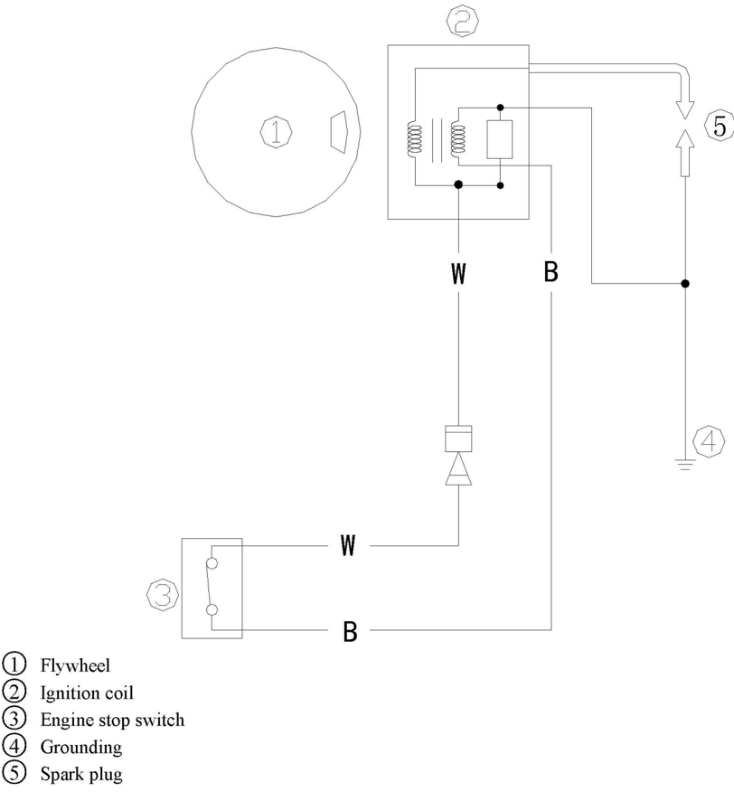
Wirebeamcolor:WWhite
B Black
Spark Plug Ignition
- Remove spark plug cap from spark plug. .
- Connect the ignition tester to the spark plug cap.
- 3.S Start the engine, and observe the sparks through the discharge window of the tester.
WARNING: Do not touch any joint part of the lead wire of the tester.
Keep away from inflammable gas or liquid, to prevent accident resulting from spark ignition.
Spark Plug Cap
- Remove the spark plug. Check if the spark plug cap is broken. Replace if necessary.
- Measure the resistance. If it's out of specification, replace. Spark plug cap resistance: 4.0~6.0k Ω
- Install the spark plug cap
Turn it clockwise until it is tight.
Flywheel Maintenance
- Use flywheel holder to remove the nut and starter pulley; use flywheel puller to remove flywheel.
- 2.Check if the flywheel is damaged or the permanent magnet part is firm. Replace if necessary.
Ignition Coil Inspection
- Ignition coil peak voltage
- 1 Remove spark plug cap.
- 2 Disconnect ignition coil tip (W).
- ③ Measure the ignition coil peak voltage output by a digital universal meter and a peak voltage adapter.If below specification, check the ignition coil.
- Ignition coil resistance
- ① Remove ignition coil and spark plug cap.
- 2 Measure ignition coil resistance.If out of specification, replace it.
Peakvoltageoutput:130V(1500r/min)
Digital universal meter
Resistance: 0.7~0.96 Q(Tester (+) pole: white wire; Tester (-) pole: black wire)
11.6~7.0k Q (Tester (+) pole: white wire; Tester (-) pole: high-voltage wire)
Peak voltage adapter
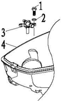
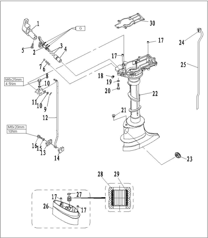
Fuel System
NOTICE: Gasoline is inflammable and highly volatile liquid. Its leakage can cause fire and explosion. Don't start the engine before all joints of the fuel system are connected or installed.When completing all maintenance steps, force short-time pressure to the fuel system to check for leakage.
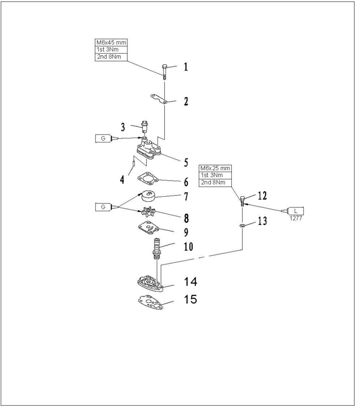
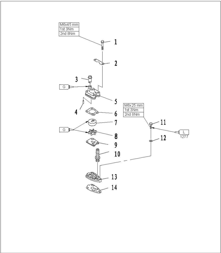
Explosive Drawing

| SN. | Part No. | Description | QTY | Remarks |
|---|---|---|---|---|
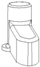
| 1 | F4-04120001 | TANK | 1 | |
| 2 | F4-04120100 | TANK COVER ASSY | 1 | |
| 3 | F4-04120103 | SPRING, PREVENT DESQUAMATING | 1 | |
| 4 | F4-04120105 | ANTI-DESQUAMATION CLIP | 2 | |
| 5 | F4-04120106 | EYELET, STEEL WIRE | 2 | |
| 6 | F4-04120104 | CHAIN, PREVENT DESQUAMATING | 1 | |
| 7 | F4-04120111 | GASKET, TANK COVER | 1 | |
| 8 | GB/T5783-2000 | HEXAGON BOLT M6×25 | 1 | |
| 9 | F4-04120002 | DAMPER, TANK | 3 | |
| 10 | F4-04120003 | BUSH, DAMPER | 3 |
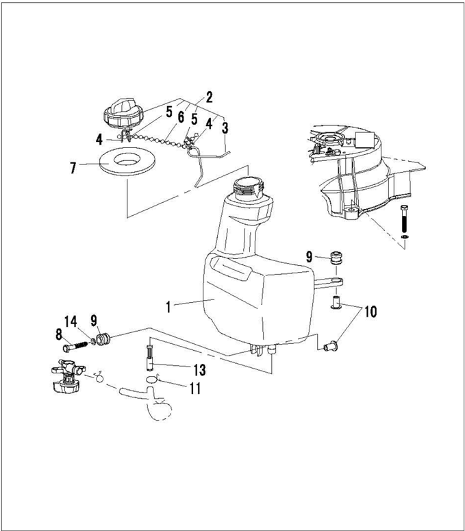
| SN. | Part No. | Description | QTY | Remarks |
|---|---|---|---|---|
| 11 | F4-04000030 | CLIP, OIL PIPE "B" | 2 | |
| 12 | F4-05000005 | PIPE, FUEL "A" | 1 | |
| 13 | F4-04120005 | STRAINER, TANK | 1 | |
| 14 | GB/T97.1-85 | WASHER, PLATE | 1 |

| SN. | Part No. | Description | QTY | Remarks |
|---|---|---|---|---|
| 1 | GB/T823-88 | SCREW, SMALL PAN HEAD M4×25 | 4 | |
| 2 | F4-04090003 | COVER, FUEL PUMP | 1 | |
| 3 | F4-04090004 | DIAPHRAGM, TOP | 1 | |
| 4 | F4-04090011 | SCREW, VALVE M3×5 | 2 | |
| 5 | F4-04090005 | PLATE (CHECK VALVE) | 2 | |
| 6 | F4-04090002 | FUEL PUMP SHELL | 1 | |
| 7 | F4-04090100 | DIAPHRAGM ASSY | 1 | |
| 8 | GB/T309-2000 | ROLLER NEEDLE 3×12 | 1 | |
| 9 | F4-04090008 | SPRING, DIAPHRAGM | 1 | |
| 10 | F4-04090001 | SEAT, FUEL PUMP | 1 |

| SN. | Part No. | Description | QTY | Remarks |
|---|---|---|---|---|
| 11 | F4-04090007 | SPRING, PLUNGER | 1 | |
| 12 | F4-04090006 | PLUNGER | 1 | |
| 13 | GB/T6170-2000 | NUT M4 | 4 | |
| 14 | F4-04090000 | FUEL PUMP ASSY | 1 | |
| 15 | F4-04090009 | O-RING | 1 | |
| 16 | F4-04000031-2 | CLIP, NYLON "B" | 1 | |
| 17 | F4-04000028 | PIPE, FUEL "E" | 1 | |
| 18 | F4-04000030 | SPRING, FUEL PIPE "B" | 9 | |
| 19 | GB/T93-1987 | WASHER, SPRING 6 | 2 | |
| 20 | GB/T97.1-85 | WASHER, PLATE 6 | 2 |
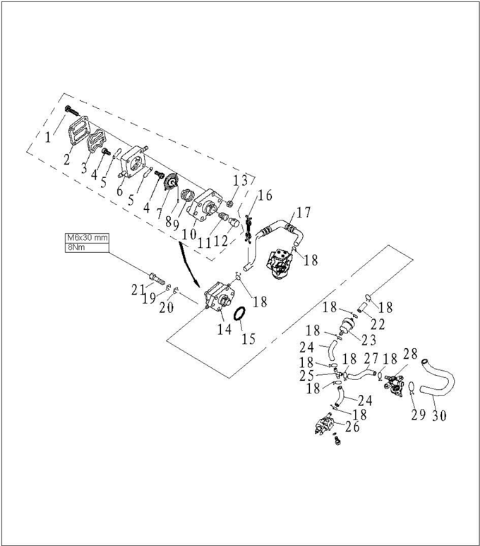
| SN. | Part No. | Description | QTY | Remarks |
|---|---|---|---|---|
| 21 | GB/T5783-2000 | HEXAGON BOLT M6×30 | 2 | |
| 22 | F4-05000008 | PIPE, FUEL "D" | 1 | |
| 23 | F4-05000300 | FUEL FILTER ASSY | 1 | |
| 24 | F4-05000007 | PIPE, FUEL "C" | 1 | |
| 25 | F15-05000011 | THREE THROUGH | 1 | |
| 26 | F4-05000300 | FUEL PIPE TIE-IN ASSY | 1 | |
| 27 | F4-05000006 | PIPE, FUEL "B" | 1 | |
| 28 | F4-05000100 | OIL SWITCH | 1 | |
| 29 | F4-05000010 | SPRING, OIL TUBE CLAMP | 1 | |
| 30 | F4-05000005 | PIPE, FUEL "A" | 1 |

| SN. | Part No. | Description | QTY | Remarks |
|---|---|---|---|---|
| 1 | GB/T5284-86 | HEXAGON BOLT M6×90 | 2 | |
| 2 | GB/T97.1-85 | WASHER, PLATE 6 | 4 | |
| 3 | F4-04110000 | SILENCER ASSY, INTAKE | 1 | |
| 4 | JASO F404-96 | O-RING 2-24-031 | 1 | |
| 5 | F4-04000024 | GASKET, CARBURETOR AIRPROOF | 2 | |
| 6 | F4-04000025 | GASKET, CARBURETOR | 1 | |
| 7 | F4-04110006 | CLAMP, NYLON DENTIFORM | 1 | |
| 8 | F4-04000035 | PIPE, RETURN GAS | 1 | |
| 9 | F4-04000031-1 | CLAMP, NYLON "A" | 1 | |
| 10 | F4-05000400 | CHOKE HANDLE ASSY | 1 |
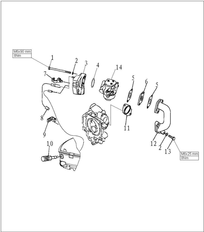
| SN. | Part No. | Description | QTY | Remarks |
|---|---|---|---|---|
| 11 | F4-04000022 | GASKET, INNER PIPE | 1 | |
| 12 | F4-04000025 | MANIFOLD, INTAKE | 1 | |
| 13 | GB/T97.1-85 | HEXAGON BOLT M6×25 | 2 | |
| 14 | F4-04000025 | CARBURETOR | 1 |
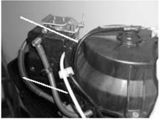
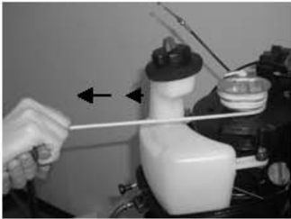
Fuel Tank Removal and Inspection
- Open the top cowling.
- 2.Remove three bolts fixing the starter.
- 3.Remove the starter. Pull thefuel tank out.
- 4.Remove the fuel pipe from fuel tank.
- Inspect the fuel tank and fuel tank cover for crack, leakage or damage. Replace if necessary.
- Inspect the tank strainer for dirt or clog. Clean or replace if necessary.

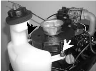
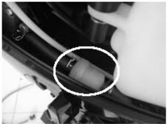
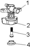
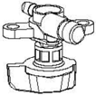
Oil Switch Removal and Inspection
- 1.Remove the fuel tank.
- 2.Remove the bolts fixing the thumb wheel of the oil switch, and remove the thumb wheel.
- Oil switch 2. Thumb wheel 3. Plus pan head screw M4X12 4. Thumb wheel block
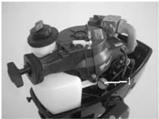
- 3.Remove the bolts fixing the oil switch, and remove oil switch.
- 1.Screw 2.Gasket 3. Oil switch 4.Bottom cowling
- Inspect the oil switch for leakage under prescribed pressure, replace if necessary. Prescribed air pressure: 0.1Mpa
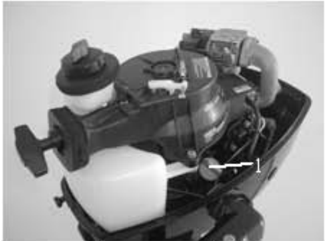
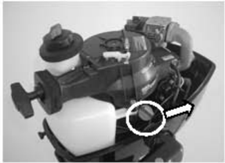
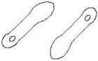
Fuel Joint Removal and Inspection
- 1.Remove the bolts fixing the fuel joint.
- Remove the fuel joint.
- Inspect the fuel joint for crack or damage.
- Connect the fuel joint exit with a vacuum pressure gauge.
- Check whether the negative pressure can be maintained for over 10 minutes under the prescribed pressure. Replace if necessary. Prescribed pressure: 50kPa.

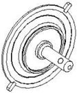
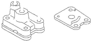
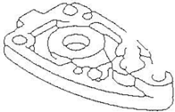
Fuel Pump Removal and Inspection
- 1.Remove the bolts fixing the fuel pump.
- Remove the fuel pump.
- 3.Connect the fuel pump intake with a vacuum pressure gauge.
- Block the exit of fuel pump with finger, and force a prescribed positive pressure to check for leakage.
- Force a prescribed negative pressure and check for leakage. Prescribed pressure:50kPa
- 6.Connect the fuel pump exit with a vacuum pressure gauge.
- Force a prescribed negative pressure and check for leakage.Disassemble the fuel pump to check if necessary. Prescribed pressure: 50kPa
- 8.Remove four bolts, and separate fuel pump cover from fuel pump seat.
- Remove the valve screw bolt from fuel pump, and remove the valve plate.
- Press the plunger and diaphragm, rotate the fuel pump seat, and align the notch with the notch on the plunger. Take the roller needle out.
- Inspect the diaphragm for crack and valve for damage. Replace if necessary.
- Reverse above step 8 to step 10 to install the fuel pump.
Prescribed pressure:50kPa
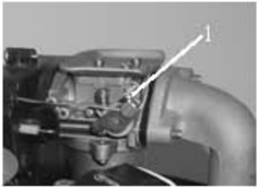
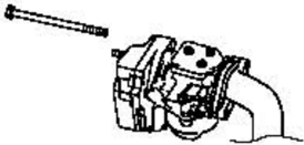
Intake System Removal and Inspection
- Loose throttle cable stop screw, and remove throttle cable.
- 2.Remove choke cable from carburetor.Remove choke cable.
- 3.Remove the bolt fixing air filter.
- 4.Remove air filter and carburetor.
- Remove intake manifold from engine.
- 6.Check if air filter and intake manifold are cracked or damaged.Replace it if necessary.
1.Throttle cable stop screw

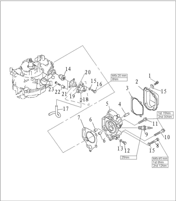
Power Unit
NOTICE: Before disassembling, disable the ignition system and turn off the ignition system. For example: remove the hang rope stopper from stop switch assembly, and remove spark plug cap from spark plug. n s e and os off the ignition system.For example: remove the hang rope stopper from stop switch assembly, and remove spark plug capfrom spark plug.
Explosive Drawing

| SN. | Part No. | Description | QTY | Remarks |
|---|---|---|---|---|
| 1 | GB/T5783-86 | HEXAGON BOLT M6×16 | 4 | |
| 2 | F4-04000018 | COVER, CYLINDER HEAD | 1 | |
| 3 | F4-04000017 | GASKET, CYLINDER COVER | 1 | |
| 4 | F4-04080002 | PIPE, VALVE | 2 | |
| 5 | F4-04080101 | CYLINDER HEAD | 1 | |
| 6 | F4-04000003 | PIN, HOLLOW | 2 | |
| 7 | F4-04000014 | GASKET, CYLINDER HEAD | 1 | |
| 8 | GB/T5782-1986 | HEXAGON BOLT M6×45 | 1 | |
| 9 | BPR7HS | PLUG, SPARK | 1 | |
| 10 | F4-04000033 | BOLT, CYLINDER HEAD "A" | 3 |

| SN. | Part No. | Description | QTY | Remarks |
|---|---|---|---|---|
| 11 | F4-04000034 | BOLT, CYLINDER HEAD "B" | 1 | |
| 12 | GB/T5783-2000 | BOLT, HEXAGON M8×14 | 1 | |
| 13 | GB/T97.1-85 | WASHER, PLATE 8 | 1 | |
| 14 | F4-04000036 | THERMOSTAT | 1 | |
| 15 | GB/T97.1-85 | WASHER, PLATE 6 | 8 | |
| 16 | GB/T5783-2000 | BOLT, HEXAGON M6×20 | 3 | |
| 17 | F4-04000012 | PIPE, RETURN | 1 | |
| 18 | F4-04010002 | SPILE, WATER | 1 | |
| 19 | F4-04070001 | COVER, THERMOSTAT | 1 | |
| 20 | F4-04070100 | COVER AND SPILE WATER ASSY | 1 |
| SN. | Part No. | Description | QTY | Remarks |
|---|---|---|---|---|
| 21 | F4-04000011 | GASKET, THERMOSTAT | 1 | |
| 22 | F4-04070000 | ANODE | 1 | |
| 23 | GB/T818-85 | SCREW, PAN HEAD M5×25 | 1 |
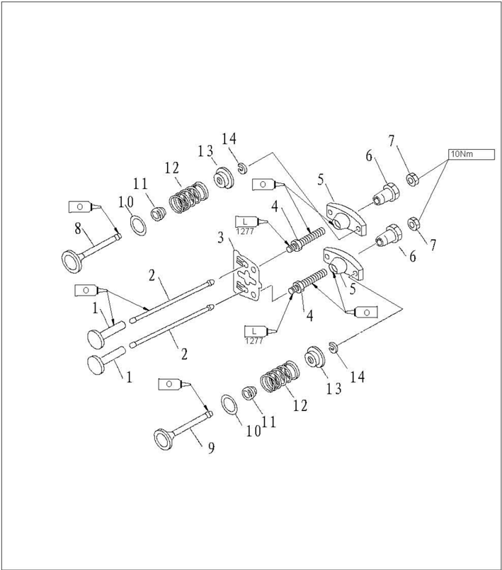
| SN. | Part No. | Description | QTY | Remarks |
|---|---|---|---|---|
| 1 | PS2700.03.02 | LIFTER, VALVE | 2 | |
| 2 | F4-04000015 | ROD, VALVE PUSH | 1 | |
| 3 | F4-04080009 | PLATE, PUSH ROD | 1 | |
| 4 | PS2700.04.12 | BOLT, ROCKER ARM | 2 | |
| 5 | PS2700.04.12 | ARM, VALVE ROCKER | 2 | |
| 6 | PS2700.04.13 | PIVOT, ROCKER ARM | 2 | |
| 7 | PS2700.04.18 | NUT, HEXAGON M6×0.75 | 1 | |
| 8 | F4-04080005 | VALVE, INTAKE | 1 | |
| 9 | F4-04080006 | VALVE, EXHAUST | 1 | |
| 10 | F4-04080007 | SEAT, VALVE SPRING | 2 |

| SN. | Part No. | Description | QTY | Remarks |
|---|---|---|---|---|
| 11 | PS2700.04.03 | SEAL, VALVE STEM | 2 | |
| 12 | F4-04080008 | SPRING, VALVE INNER | 2 | |
| 13 | F4-04080010 | RETAINER, VALVE SPRING | 2 | |
| 14 | F4-04080011 | CLAMP, VALVE | 2 |

| SN. | Part No. | Description | QTY | Remarks |
|---|---|---|---|---|
| 1 | F4-04010100 | CRANK CASE | 1 | |
| 2 | F4-04010002 | PIPE, JOINT | 1 | |
| 3 | F4-04010003 | OIL SEAL A25×40×5 | 1 | |
| 4 | GB/T276-94 | BEARING 6205C3 | 1 | |
| 5 | F4-04000009 | BREATHER GASKET | 1 | |
| 6 | F4-04000010 | COVER, BREATHER | 1 | |
| 7 | GB/T5782-2000 | HEXAGON BOLT M6×14 | 3 | |
| 8 | GB/T97.1-85 | WASHER, PLATE 6 | 3 | |
| 9 | GB/T818-85 | SCREW, PAN HEAD M4×6 | 1 | |
| 10 | F4-04010003 | VALVE, BREATHER FLAP | 1 |

| SN. | Part No. | Description | QTY | Remarks |
|---|---|---|---|---|
| 11 | F4-04000003 | HOLLOW PIN Φ10×8.4×14 | 2 | |
| 12 | F4-04050001 | COVER, CRANK CASE | 1 | |
| 13 | F4-04000002 | CRANK CASE COMPLEX GASKET | 1 | |
| 14 | GB/T5787-1986 | HEXAGON FLANGE BOLT M8×50 | 7 | |
| 15 | F4-04060003 | OIL SEAL 20×30×7 (B) | 1 | |
| 16 | F4-04060004 | OIL SEAL 10.8×21×7 | 2 | |
| 17 | F4-04060002 | O-RING | 1 | |
| 18 | F4-04060001 | SHELL, OIL SEAL | 1 | |
| 19 | F4-04060000 | OIL SEAL SHELL ASSY | 1 | |
| 20 | GB/T97.1-85 | WASHER, PLATE 8 | 8 |
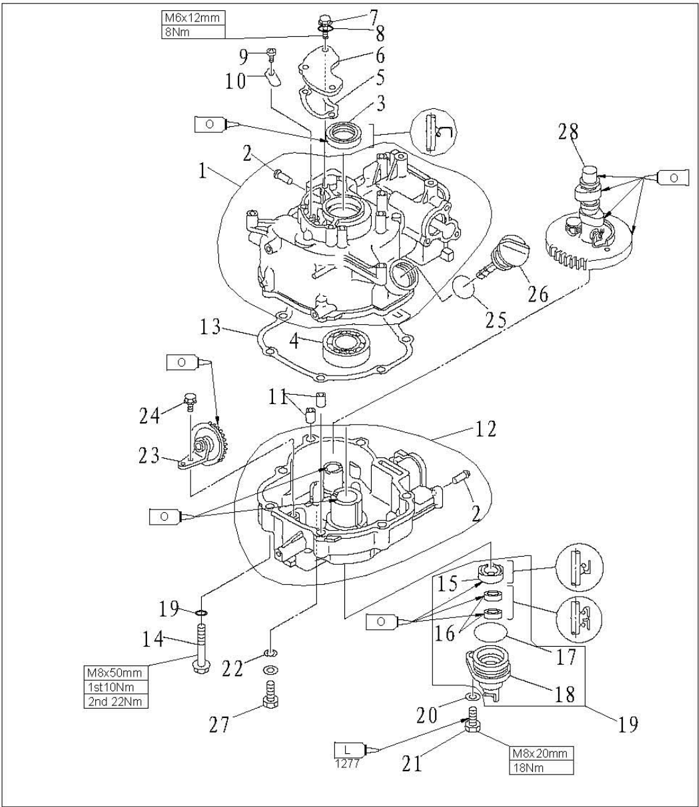
| SN. | Part No. | Description | QTY | Remarks |
|---|---|---|---|---|
| 21 | GB/T5783-2000 | HEXAGON BOLT M8×20 | 1 | |
| 22 | F4-04000006 | WASHER | 1 | |
| 23 | F4-04050000 | GEAR UNIT ASSY | 1 | |
| 24 | GB/T5783-2000 | BOLT, HEXAGON M6×12 | 1 | |
| 25 | F4-04000008 | O-RING | 1 | |
| 26 | F4-04000007 | PLUG WITH DIPSTICK | 1 | |
| 27 | F4-04000001 | BOLT, DISCHARGING OIL | 1 | |
| 28 | F4-04040000 | CAMSHAFT ASSY | 1 |
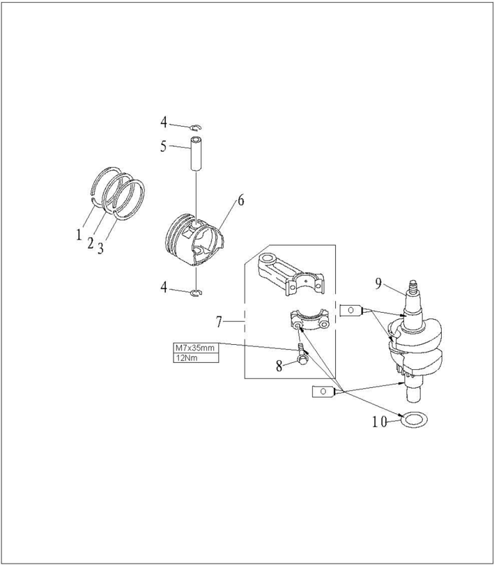
| SN. | Part No. | Description | QTY | Remarks |
|---|---|---|---|---|
| 1 | F4-04020002 | PISTON RING 1 | 1 | |
| 2 | F4-04020003 | PISTON RING 2 | 1 | |
| 3 | F4-04020004 | COMBINED OIL RING | 1 | |
| 4 | F4-04020006 | CIRCLIP | 2 | |
| 5 | F4-04020005 | PIN, PISTON | 1 | |
| 6 | F4-04020001 | PISTON | 1 | |
| 7 | F4-04020100 | ROD, CONNECTING | 1 | |
| 8 | F4-04020103 | BOLT, ROD CLEVEL | 2 | |
| 9 | F4-04030000 | CRANK ASSY | 1 | |
| 10 | F4-04000004 | WASHER, PLATE | 1 |
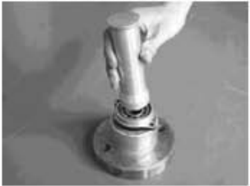
Piston slider
Housing bearing installer
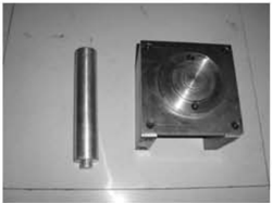
Space gauge
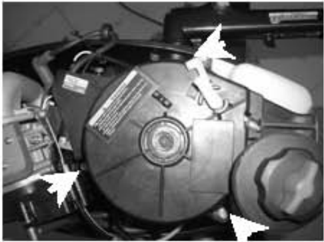
Disassembling Power Unit from Outboard Engine
- 1.Open the top cowling.
- 2.Remove the starter and fuel pump.
- 3.Remove choke cable and throttle cable.
- 4.Removeairfilter andcarburetor.
- 5.Remove bolts connecting the engine and upper casing.
- 6.Carry the power unit and put it onto the working table.
Disassembling and Inspection (Power Unit)
Special Tools
Bearing puller
Oilsealinstallertool
Valve spring compressor
Housing oil seal installer
Cylinder Cover
Disassembling
- Remove the bolts of cylinder head cover.
- 2.Remove the bolts of the cylinder cover according to the reverse numbering sequence of the cylinder cover.
- 3.Remove the crankcase cover.Remove the valve push rod
- 4.Remove the rocker arm pivot, rocker arm, rocker arm shaft and push rod plate.
Push rod
Inspect valve push rod runout.Replace if exceeding the specified value. Valve push rod runout limit: 0.5mm
Valve and valve pipe
- 1.Inspect the valve seat width. If not in the prescribed range,repair the valve seat. Valve seatwidth:0.6~0.8mm
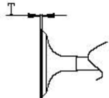
- 2.Inspect the valve margin thickness (T).If not as in the prescribed value,replace the valve. The margin thickness of valve: T
- 3.Inspect the valve stem diameter.If not in the prescribed range, replace the valve. The diameter of valve stem:
Intake door:0.7mm
Exhaust door:1.00mm
Intake:5.475~5.490mm
Exhaustvalve:5.460~5.475mm
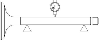
- 4.Measure the valve stem runout.If exceeding the limit, replace the valve. Valve stem runout limit:0.03mm
- 5.Measure the inner diameter of the valve pipe. Theinner diameter of thevalve pipe: 5.500~5.512mm
CAUTION: When replacing the valve, please use the new valve pipe and valve oil seal.
Valve spring
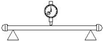
- Measure the free length of valve spring. If less than prescribed value, replace. The minimum free length: 34mm
- 2.Measure the valve spring tilt. If exceeding the prescribed limit, replace.
The maximum tilt limit: 1.2mm
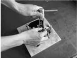
- 1.Clean the carbon on the valve.
- 2.Coat a thin layer of bluing dye evenly onto the seal face of the valve seat.
- 3.Lap the valve on valve seat by valve lapping tool.
- 4.Measure thevalveseatwidth. The valve face is with bluing dye. If the valve and valve seat do not match, or the valve seat width does not conform to specified value,reface and lap thevalve seat.
If the contact surface is not even, replace the valve pipe.
Valve rocker arm
Check the rocker arm for crack, perforation or damage.Replace if necessary.
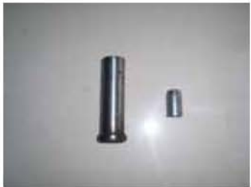
Valve pipe replacement
- 1.Knock out the valve pipe from the direction of combustion room.
- 2.Knock in the new valve pipe from the direction of the top of cylinder cover. NOTE:
Coat the oil on the surface of pipe before installation.
- 3.Bore the inner diameter of pipe to the prescribed value by reamer.
Inner diameter of valve pipe: 5.500~5.512mm
NOTE: When taking out the reamer, don't rotate it in counter clockwise direction.
Valve seat inspection
Thevalveseatwidth:
0.6~0.8mm
Themaximumvalveseatwidth:
1.1mm
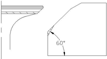
Valve seat cutting
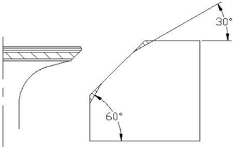
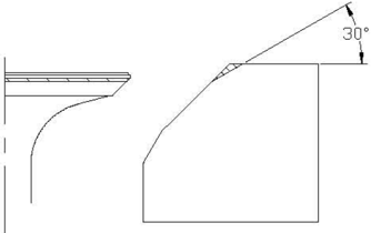
- 1.Use 45° cutter to adjust the valve seat width. Turn the cutter clockwise until the valve seat face is smooth.
- 2.If the valve seat is centered on the valve face but it's too wide,to reduce the valve seat width, use 30° cutter to adjust the top edge of the seat, and use 60° cutter to adjust the bottom edge of the seat.
- 3.If the valve seat is too narrow and on the top edge of valve surface, use 30°cutter to adjust the top margin of the seat, and use 45° cutter to adjust the valve seat width if necessary.
- 4.If the valve seal surface is too narrow and on the bottom edge of valve surface,use 60°cutter to adjust the bottom edge of the seat, and use 45° cutter to adjust the valve seat width if necessary.
- 5.Coat evenly a thin layer of lapping compound onto valve seat, and lap the valve by lapping tool.
- Clean up the remaining lapping compound.
- 7.Inspect again the valve seat width.
CAUTION: Do not overlap the valve.Turn the lapping tool evenly with a downward force of 40~50N. Do not contaminate push rod and valve pipe with lapping compound.
Thermostat
- 1.Remove thermostat cover and thermostat.
- 2.Suspend thermostatin the containerwithwater.
- 3.Heat the container.
- Inspect valve lift situation in the prescribed water temperature. If out of specification, replace.
- 5.Install thermostat and thermostat cover.Tighten the bolts to specified torque.
| Water temperature | The lift height |
|---|---|
| 58~62℃ | 0.05mmvalvelift |
| Over 70℃ | Over 3mm |
Crankcase
Disassembling:
- 1.Remove the bolts according to the reverse numbering sequence of the crankcase cover.
- 2.Remove the cover of crankcase.
- Remove the camshaft and valve lifter.
- Remove the connecting rod bolt and connecting rod cap,and remove connecting rod and piston assembly.
- Use clipper to remove circlip, and remove piston pin and piston.
- 6.Remove crankcase and crankcase gasket.
- Remove oil splasher gear assembly.
- 8.Removebreathercover bolts,and remove breather cover.
- 9.Remove valve bolts and remove valve.
- 10.Remove oil seal shell bolts, and remove oil seal shell and oil seal.
Breather
- Inspect breather flap valve, if damaged/cranked/cracked, replace.
- 2.Inspect breather hole. If clogged, clean.
- Inspect breather return pipe. If cracked/leaked/damaged, replace.
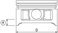
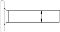
Piston
Measure piston outside diameter at the specified measuring point. If out of specification, replace.
Pistondiameter:58.950~58.965mm
Measuring point@: 10mm
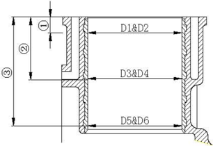
Cylinder bore
- Measure cylinder bore separately at measuring point ①, O, ③. At each point, measure the cylinder bore at places D1, D3, D5 parallel to the crankcase and at places D2, D4,D6 vertical to the crankshaft.
Measuring point height:
①100mm;
②40mm;
③70mm
Cylinder bore:
59~59.02mm
59.10mm
Limit size:
- Calculate taper limit and round limit. If out of specification, replace crankcase.
Taper limit: 0.08mm(D1-D5, D2-D6)
Round limit: 0.05mm(D2-D1, D6-D5)
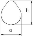
Piston pin diameter
Measure piston pin outside diameter. If out of specification, replace the piston pin. Piston pin outside diameter:12.995~13.000mm
Piston ring
- 1.Push the piston ring parallel with the piston crown into the specified measuring point of the cylinder (1omm from conjunction surface).
- 2.Measure end gap by space gauge. If out of specification, replace the piston ring.
End gap (installed) / limit size:
Top ring 0.10~0.20mnm/0.4mm
2nd ring 0.25~0.40mm/0.6mm
Oil ring0.2~0.7mm/0.9mm
- Install piston ring to piston, and measure side clearance between piston ring and its slot by clearance gauge. If out of specification, replace the piston ring.
Side clearance:
Top ring 0.04~0.08mnm
2nd ring 0.02~0.06mm
Camshaft decompressor
- 1.Inspect camshaft decompressor, gear, and weight.If gear is worn/damaged/cracked, replace.
If weight is unsmoothly moving, replace.
- 2.Measure camshaft lobe diameter@ and height .If out of specification, replace it.
@Intake camshaft:21.950~22.050mm
Exhaust camshaft:21.950~22.050mm
b
- ?
Intake camshaft:26.736~26.836mm
Exhaustcamshaft:26.532~26.623mm
- 3.Measure camshaft diameter. If out of specification, replace the camshaft.
a
Camshaft journal wear limit:14.934mm
Crankshaft
Measure crankshaft runout.If out of specification, replace.

Crankshaft runout limit: 0.03mm
Oil clearance
- Put a piece of plastic space gauge on to the crankpin in parallel to the crankshaft.
- Assemble the connecting rod to the crankpin.
- 3.Tighten the connecting rod bolts to the specified torque.
12Nm
Tightening torque:
- Remove the connecting rod, measure the compressed width of the plastic space gauge. If out of specification, replace the connecting rod.
Oil clearance:
0.020~0.052mm
Note:
Don't rotate the connecting rod before completing measurement.
Valve lifter
- 1.Inspect valve lifter for wear or damage. Replace if necessary.
- 2.Measure valve lifter outside diameter. If out of specification, replace the valve lifter.
Valvelifter outside diameter:7.9650mm
Oil splash gear
Inspect oil splash gear unit, if slow-moving/wear/damage/crack, replace.
Crankshaft bearing
Inspect bearing, if pitting/rumbling, replace.
NOTE: Don't remove bearing unless you replace it.
Oil seal housing
- Inspect oil seal housing for crack/damage. Replace if necessary.
- Inspect O-ring for crack/damage. Replace if necessary.
Crankcase and crankcase cover
- Inspect crankcase cover.If cracked/damaged, replace.
- Inspect cooling water passage for dirt or clog.Clean if necessary.
Full Installation
Piston connecting rod installation
Install piston, connecting rod, piston pin and piston pin circlip.
NOTE: When installing, make sure that the mark on the connecting rod is at the same side of the mark on the piston crown.
Use new piston pin circlip. Make sure that circlip gap is not aligned with the circlip slot gap.

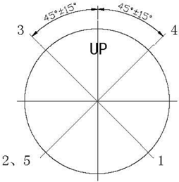
Piston ring installation
- Install oil ring, 2nd ring and top ring. NOTE: Make sure that the mark is toward the piston crown when installing the 2nd ring.
- Picture of the piston ring gap Oil ring end gap 1 (lower rail) Oil ring end gap 2 (expanded ring) Oil ring end gap 3 (upper rail) 2nd piston ring end gap 4
Top piston ring end gap 5
Piston installation
Use piston slider to install piston, and make sure the piston crown Up"is toward the flywheel side.
NOTE: Apply motor oil to the piston and piston ring side when installing.
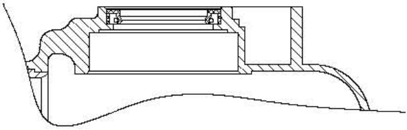
Oil seal housing installation
- Install oil seals 10.8x21x7 (2 pieces) by oil seal installer tool.
- 2.Install oil seals B20 X 30 X 7 by oil seal installer tool.
NOTE:
- ① Apply grease onto new seal before installation.
- ② Make sure the oil seal direction as shown.
Crankshaft installation
- Install the crankshaft bearing to crankcase by special tools (if change bearing). Install oil seal.
Housing oil seal installer
Oil seal installing direction
Housing bearing installer

NOTE: Fit the bearing with its manufacturer's mark toward the direction of the flywheel side.Apply motor oil to the new oil seal installing.
- Install crankshaft to crankshaft case.
- Install connecting rod cover, and tighten the connecting rod bolt to the specified torque. Specified torque: 12 Nm
NOTE: Apply motor oil to moving parts before installing.
Camshaft installation
Install camshaft. Make sure that the camshaft gear mark is aligned with the camshaft timing gear mark.
NOTE: Apply motor oil to moving parts before installing.
NOTE: Apply motor oil to moving parts before installing.
Upper Unit
Top Cowling
Explosive Drawing
Crankcase cover installation
- Install oil seal housing.
- 2 Install oil splasher gear assembly.
- 3 Install crankcase cover, and tighten the bolts twice as shown.
Tightening torque:
1st 10 Nm
2nd 22 Nm

| SN. | Part No. | Description | QTY | Remarks |
|---|---|---|---|---|
| 1 | F4-06000000 | TOP COWLING ASSY | 1 | |
| 2 | GB/T8.8-2000 | SCREW, PAN HEAD M5×12 | 2 | |
| 3 | F4-06000005 | HOOK, LOCK | 1 | |
| 4 | F4-06000002 | BAR RUBBER, AIRPROOF | 1 | |
| 5 | GB/T845-85 | SCREW, TAPPING ST5.5×19 | 4 | |
| 6 | F4-06000003 | COVER, TOP COWLING MUFFLING | 1 | |
| 7 | F15-08000004 | POTHOOK | 1 | |
| 8 | F4-06000001 | TOP COWLING | 1 | |
| 9 | GB/T818-2000 | SCREW, PAN HEAD M5×20 | 2 | |
| 10 | GB/T6172.1-2000 | THIN NUT, HEXAGON M5 | 2 |
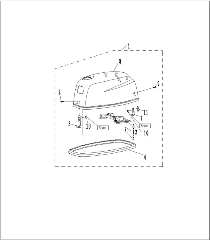
| SN. | Part No. | Description | QTY | Remarks |
|---|---|---|---|---|
| 11 | F4-06000006 | UNDERLAY, POTHOOK | 1 | |
| 12 | F4-06000004 | UNDERLAY, RUBBER | 4 |
Disassembling and inspection
- Remove airproof rubber bar.
- Remove top cowling muffling cover bolt and rubber underlay.
- Remove top cowling muffling cover.
- Remove lock hook and pothook.
- Inspect if top cowling is cracked or damaged. Replace it if necessary.
- Inspect if airproof rubber bar is cracked or damaged.Replace it if necessary.
- Inspect if top cowling muffling cover is cracked or damaged.Replace it if necessary.
- Inspect if lock hook and pothook is cracked, deformed or damaged. Replace it if necessary.
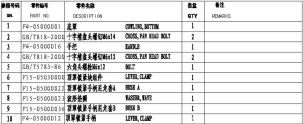
Bottom Cowling
Explosive drawing
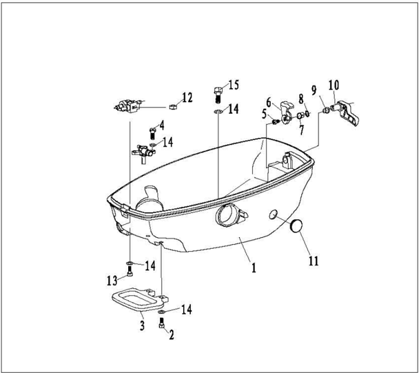
| SN. | Part No. | Description | QTY | Remarks |
|---|---|---|---|---|
| 1 | F4-05000001 | COWLING, BOTTOM | 1 | |
| 2 | GB/T818-2000 | CROSS PAN HEAD BOLT M6×14 | 2 | |
| 3 | F4-05000016 | HANDLE | 1 | |
| 4 | GB/T818-2000 | CROSS PAN HEAD BOLT M6×12 | 2 | |
| 5 | GB/T5783-86 | BOLT M6×12 | 1 | |
| 6 | F15-05030000 | LEVER, CLAMP | 1 | |
| 7 | F15-05000022 | BUSH A | 1 | |
| 8 | F15-05000023 | WASHER, WAVE | 1 | |
| 9 | F15-05000036 | BUSH B | 1 | |
| 10 | F4-05000012 | LEVER, CLAMP | 1 |
| SN. | Part No. | Description | QTY | Remarks |
|---|---|---|---|---|
| 11 | F4-05000013-2 | COVER, RUBBER B | 1 | |
| 12 | GB/T6170-86 | NUT, HEXAGON M6 | 1 | |
| 13 | GB/T5783-2000 | BOLT, HEXAGON M6×25 | 1 | |
| 14 | GB/T97.1-85 | WASHER, PLATE 6 | 12 | |
| 15 | GB/T5783-2000 | BOLT, HEXAGON M6×14 | 7 |
Disassembling and inspection
- Remove rubber coverB.
- Remove handle bolt and handle.
- Remove top cowling clamp lever bolt and clamp lever.
- Removetopcowling clampleverbushA and clampleverbushB.
- Removewavewasher.
- Inspect if bottom cowling is cracked or damaged. Replace if necessary.
- Inspect if clamp lever handle is cracked or damaged.Replace if necessary.
- Inspect if clamp lever is cracked or damaged.Replace if necessary.
- Inspect ifwave washer and clampleverbush are cracked or damaged.Replace if necessary.
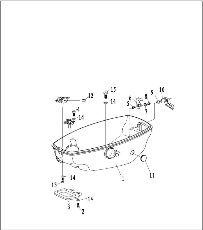
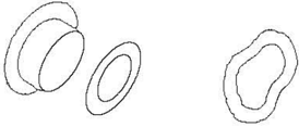
Steering Handle
Explosive drawing
| SN. | Part No. | Description | QTY | Remarks |
|---|---|---|---|---|
| 1 | F4-01090001 | HANDLE, STEERING | 1 | |
| 2 | F4-01000009 | BUSHING, HANDLE | 1 | |
| 3 | F4-01000012 | BUSH, WAVE WASHER | 1 | |
| 4 | F4-01000010 | WASHER, BUSHING | 2 | |
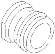
| 5 | F4-05000014 | BUSHING, RUBBER | 1 | |
| 6 | F4-01000011 | WASHER, BUSHING | 1 | |
| 7 | F4-01000008 | BUSHING | 1 | |
| 8 | F4-01000014 | COVER, HANDLE STEERING | 1 | |
| 9 | GB/T5783-2000 | BOLT M8×25 | 1 | |
| 10 | GB/T91-86 | PIN, COTTER 1.6×12 | 1 |

| SN. | Part No. | Description | QTY | Remarks |
|---|---|---|---|---|
| 11 | F4-01090200 | BOLT, FRICTION ADJUSTING | 1 | |
| 12 | F4-01090006 | BUSH | 1 | |
| 13 | F4-01090007 | SPRING, COMPRESSION | 1 | |
| 14 | GB/T848-85 | WASHER, PLATE | 1 | |
| 15 | F4-01090303 | INDICATOR, THROTTLE | 1 | |
| 16 | F4-01090301 | GRIP, STEERING HANDLE | 1 | |
| 17 | F4-01090302 | RUBBER, HANDLE | 1 | |
| 18 | GB/T820-85 | SCREW M5×24 | 1 | |
| 19 | GB/T827-86 | RIVET 2×5 | 1 | |
| 20 | F4-01090300 | STEERING HANDLE ASSY | 1 |
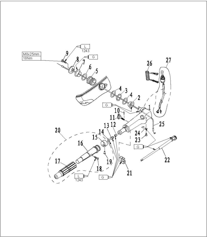
| SN. | Part No. | Description | QTY | Remarks |
|---|---|---|---|---|
| 21 | F4-01090003 | FRICTION | 1 | |
| 22 | F4-01090100 | LEVER, THROTTLE | 1 | |
| 23 | GB/T818-85 | SCREW, PAN HEAD M5×12 | 2 | |
| 24 | F4-01090002 | STAY | 1 | |
| 25 | F4-01090008 | THROTTLE CABLE ASSY | 1 | |
| 26 | F4-01090401 | STOPPER, HANG ROPE ASSY | 1 | |
| 27 | F4-01090400 | ENGINE STOP SWITCH ASSY | 1 |
Disassembling and inspection
- Remove steering handle cover.
- Remove handle bush, bush washer and wave washer.
- Remove steering handle shocker damper.
- Remove cotter pin and friction adjusting bolt
- Remove steering handle.
- Remove throttle cable.
- Removethrottleleverstayand throttlelever.
- Remove engine stop switch.
- Inspect if steering handle is cracked or damaged. Replace if necessary.
- necessary.
- Inspect if steering handle shock damper is cracked or damaged. Replace if necessary.
- Inspect if throttle cable is cracked or damaged. Replace if necessary.
- Inspect the conduction of engine stop switch. If not to specification, replace it.
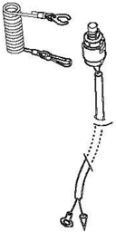
Remove lockplate:
Conducting Not conducting
Install lockplate:
Push stop switch button: Conducting
Bracket
Explosive drawing
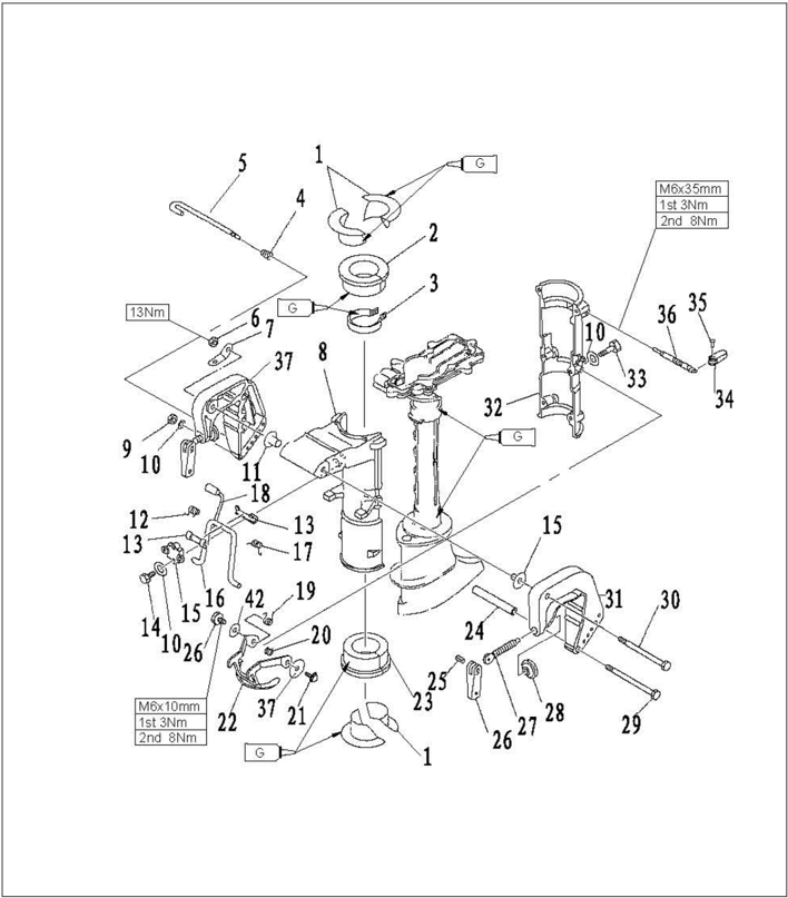
| SN. | Part No. | Description | QTY | Remarks |
|---|---|---|---|---|
| 1 | F4-02000008 | BUSH, SHOCK ABSORPTION | 4 | |
| 2 | F4-02000007 | TOP, SHOCK ABSORPTION | 1 | |
| 3 | F4-02020000 | UPPER LOCKING RING ASSY | 1 | |
| 4 | F4-01050002 | SPRING, CONICAL | 1 | |
| 5 | F4-01050000 | TILT ROD ASSY | 1 | |
| 6 | GB/T889.1-2000 | NUT M8 | 1 | |
| 7 | F4-01000002 | PLATE | 2 | |
| 8 | F4-01030001 | BRACKET, SWIVEL | 1 | |
| 9 | GB/T6170-86 | HEXAGON NUT M6 | 1 | |
| 10 | GB/T97.1-85 | WASHER | 11 |
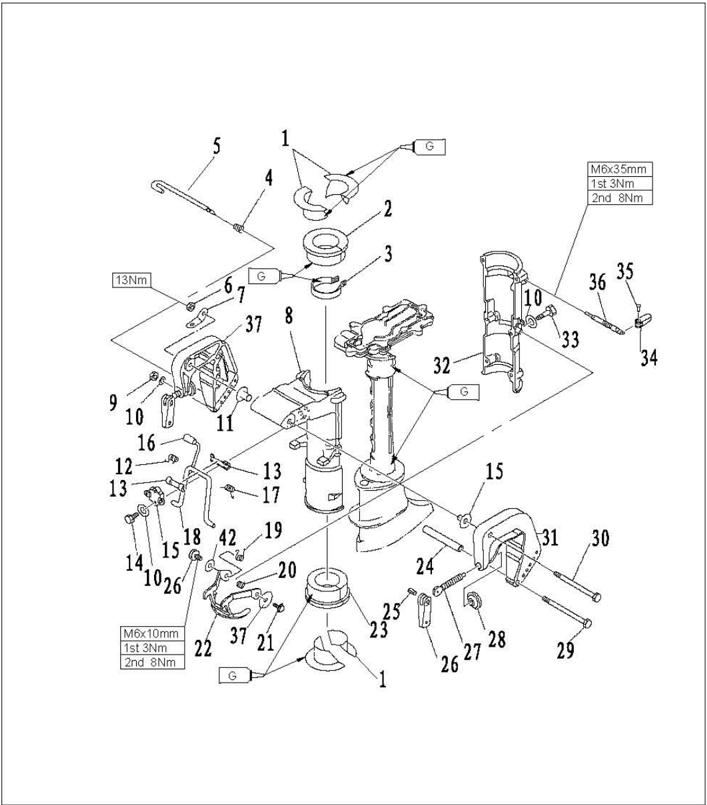
| SN. | Part No. | Description | QTY | Remarks |
|---|---|---|---|---|
| 11 | F4-01000003 | WASHER, NYLON | 2 | |
| 12 | F4-01030003 | SPRING, TORSION (LEFT) | 1 | |
| 13 | F4-01030002 | BUSHING, NYLON | 2 | |
| 14 | GB/T5783-2000 | HEXAGON BOLT M6×20 | 2 | |
| 15 | F4-01030005 | FIXED COVER, BRACKET | 1 | |
| 16 | F4-01030103 | SHEATH, HANDLE | 2 | |
| 17 | F4-01030004 | SPRING, TORSION (RIGHT) | 1 | |
| 18 | F4-01030100 | BRACKET, TILT LOCK | 1 | |
| 19 | F4-01000006 | SPRING | 1 | |
| 20 | F4-01000007 | SPRING | 1 |

| SN. | Part No. | Description | QTY | Remarks |
|---|---|---|---|---|
| 21 | GB/T5783-2000 | HEXAGON BOLT M6×12 | 2 | |
| 22 | F4-01070000 | TILT LOCKED CLASP ASSY | 1 | |
| 23 | F4-02000009 | BOTTOM ABSORPTION ASSY | 1 | |
| 24 | F4-01000004 | BUSHING, BOLT | 1 | |
| 25 | F4-01010005 | RIVET, CLAMP HANDLE | 2 | |
| 26 | F4-01010004 | CLAMP SHIPBOARD HANDLE | 2 | |
| 27 | F4-01010002 | CLAMP BOLT | 2 | |
| 28 | F4-01010003 | CLAMP PLATE | 2 | |
| 29 | GB/T5782-2000 | HEXAGON BOLT M6×120 | 1 | |
| 30 | GB/T5782-2000 | HEXAGON BOLT M8×135 | 1 |

| SN. | Part No. | Description | QTY | Remarks |
|---|---|---|---|---|
| 31 | F4-01010001 | BRACKET, CLAMP (RIGHT) | 1 | |
| 32 | F4-01000005 | COVER, SWIVEL BRACKET | 1 | |
| 33 | GB/T5782-86 | HEXAGON BOLT M6×35 | 6 | |
| 34 | F4-01060002 | CLAMP HANDLE | 1 | |
| 35 | GB/T875-86 | RIVET 4×11 | 1 | |
| 36 | F4-01060001 | LOCKED SCREW | 1 | |
| 37 | GB/T96-1985 | BIG WASHER | 2 | |
| 38 | F4-01020000 | BRACKET, LEFT ASSY | 1 |
- 1.Remove tilt locked clasp.
- Remove swivel bracket cover.
- 3.Remove bottom shock absorption assembly and shock absorption bush.
Disassembling and inspection
Remove clamp bracket.
- 5..Removeswivelbracket.
- 6.Remove bracket fixed cover, and the tilt lock bracket.
- Inspect the the swivel bracket and clamp bracket for damage or crack. Replace if necessary.
- 8.Inspect the bush and shock absorption for damage or crack.Replace if necessary.
- 9.Inspect:whether the tilt lockbracket and tilt locked clasp were distorted,replace if needed.

Upper Unit Casing
Explosive drawing

| SN. | Part No. | Description | QTY | Remarks |
|---|---|---|---|---|
| 1 | F4-00000007 | HANDLE, GEAR SHIFT | 1 | |
| 2 | F4-02010000 | SHAFT, CHANGE | 1 | |
| 3 | JISB2401 | O-RING P9 | 2 | |
| 4 | F4-02000002 | BUSHING, SHIFT ROD LEVER | 1 | |
| 5 | GB/T820-2000 | SCREW, OVAL HEAD M5×20 | 1 | |
| 6 | F4-02000003 | SPRING, GEAR | 1 | |
| 7 | GB308-84 | BALL 8 | 1 | |
| 8 | GB/T5783-2000 | BOLT M5×25 | 1 | |
| 9 | GB/T308-84 | PIN, COTTER 1.6×12 | 1 | |
| 10 | GB/T97.1 | WASHER, PLATE 5 | 2 |

| SN. | Part No. | Description | QTY | Remarks |
|---|---|---|---|---|
| 11 | F4-02000006 | LEVER, SHIFT ROD | 1 | |
| 12 | F4-02000004 | ROD, SHIFT | 1 | |
| 13 | F4-00000003 | CONNECTOR, SHIFT ROD A | 1 | |
| 14 | F4-00000004 | CONNECTOR, SHIFT ROD B | 1 | |
| 15 | F4-00000005 | BIG WASHER | 1 | |
| 16 | GB/T5284-86 | BOLT M6×20 | 1 | |
| 17 | F4-00000001 | PIN, HOLLOW | 4 | Type S: 2 |
| 18 | JB/T7940.1-95 | GREASE CUP M6 | 1 | |
| 19 | GB/T97.1-85 | WASHER | 7 | |
| 20 | GB/T5284-86 | HEXAGON BOLT M6×35 | 7 |
| SN. | Part No. | Description | QTY | Remarks |
|---|---|---|---|---|
| 21 | F4-02000011 | WASHER, SHIFT ROD | 1 | |
| 22 | F4-02000001 | CASING, UPPER | 1 | |
| 23 | F4-02000012 | RUBBER PLUG, UPPER | 2 | |
| 24 | F4-02040002 | I-SHAPED RUBBER BAND | 1 | |
| 25 | F4-02040000 | WATER TUBE | 1 | Type S: F4-02040000S |
| 26 | F4-02030001 | EXTENSION | 1 | L |
| 27 | GB/T 893.1-1986 | CIRCLIP 22 | 1 | L |
| 28 | F4-02030003 | RUBBER BUSHING | 1 | L |
| 29 | F4-02030002 | BUSHING, DRIVE SHAFT | 1 | L |
| 30 | F4-00000006 | GASKET, ENGINE | 1 |
Disassembling and inspection
- Remove the water tube.
- 2.Remove the gear shift handle and change shaft.
- 3.Remove the shift rod and shift rod lever.
- 4.Check upper casing and extension for crack or wear. Replace if necessary.
- 5.Check gear shift handle and change shaft for crack or wear. Peplace if necessary.
Lower Unit
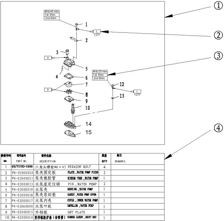
Water Pump Assembly
Explosive drawing
| SN. | Part No. | Description | QTY | Remarks |
|---|---|---|---|---|
| 1 | GB/T5782-2000 | HEXAGON BOLT M6×45 | 4 | |
| 2 | F4-03000020 | PLATE, WATER PUMP FIXED | 2 | |
| 3 | F4-03000021 | RUBBER TUBE, WATER PUMP | 1 | |
| 4 | F4-03000013 | PIN, WATER PUMP | 2 | |
| 5 | F4-03000019 | HOUSING, WATER PUMP | 1 | |
| 6 | F4-03000018 | GASKET, WATER PUMP COVER | 1 | |
| 7 | F4-03000017 | COVER, INNER WATER PUMP | 1 | |
| 8 | F4-03060000 | IMPELLER, WATER PUMP | 1 | |
| 9 | F4-03000015 | OUT PLATE | 1 | |
| 10 | F4-03000014 | RUBBER JACKET, SHIFT ROD | 1 |
| SN. | Part No. | Description | QTY | Remarks |
|---|---|---|---|---|
| 11 | GB/T5783-2000 | HEXAGON BOLT M6×25 | 1 | |
| 12 | GB/T97.1-85 | WASHER, PLATE | 5 | |
| 13 | F4-03000012 | BASE, WATER PUMP | 1 | |
| 14 | F4-03000011 | HERMETIC GASKET | 1 |
Disassembling and inspection
- Remove water pump fixed plate.
- Remove water pump housing.
- Remove water pump impeller and inner water pump cover.
- 4.Remove water pump base.
- 5.Check water pump housing and out plate for crack, crank or damage. Replace if necessary.
- Check inner water pump cover and impeller for crack, deform, burn or damage. Replace if necessary.
- Check water pump base for crack, crank, scratch or damage. Replace if necessary.


Lower Unit Gear Assembly
Explosive Drawing
| SN. | Part No. | Description | QTY | Remarks |
|---|---|---|---|---|
| 1 | GB/T91-86 | PIN, COTTER 2.5×30 | 1 | |
| 2 | F4-03080000 | NUT ASSY | 1 | |
| 3 | F4-03000026 | WASHER | 1 | |
| 4 | F4-03070000 | PROPELLER ASSY | 1 | |
| 5 | F4-03000025 | SPACER | 1 | |
| 6 | F4-03000022 | ANODE | 1 | |
| 7 | GB/T97.1-85 | WASHER, PLATE | 1 | |
| 8 | GB/T861.1-87 | WASHER, INTERNAL TOOTH | 1 | |
| 9 | GB/T5783-2000 | HEXAGON BOLT M6×12 | 1 | |
| 10 | F4-00000001 | HOLLOW PIN | 2 |

| SN. | Part No. | Description | QTY | Remarks |
|---|---|---|---|---|
| 11 | F4-03000027 | OIL SEAL 10.8×21×7 | 2 | |
| 12 | F4-03000009 | WASHER, REVERSE GEAR | 2 | |
| 13 | F4-03040000 | REVERSE GEAR ASSY | 1 | |
| 14 | GB/T276-94 | BEARING 6004C2 | 2 | |
| 15 | F4-03050002 | OIL SEAL 13×22×7 | 2 | |
| 16 | JISB2401 P48 | O-RING | 1 | |
| 17 | F4-03050001 | COVER, LOWER CASING | 1 | |
| 18 | GB/T97.1-85 | WASHER, PLATE | 5 | |
| 19 | GB/T5783-2000 | HEXAGON BOLT M6×18 | 2 | |
| 20 | F4-03000003 | BEARING | 1 |

| SN. | Part No. | Description | QTY | Remarks |
|---|---|---|---|---|
| 21 | F4-03000023 | PLUG, OIL HOLE | 3 | |
| 22 | F4-03000024 | GASKET | 3 | |
| 23 | F4-03000001 | LOWER CASING | 1 | |
| 24 | GB/T-896-86 | CIRCLIP | 1 | |
| 25 | F4-03000007 | INITIATIVE GEAR | 1 | |
| 26 | F4-03000006 | WASHER, INITIATIVE GEAR | 1 | |
| 27 | F4-03000002 | BEARING | 1 | |
| 28 | F4-03000008 | PLUNGER, SHIFT | 1 | |
| 29 | F4-03010000 | POSITIVE GEAR ASSY | 1 | |
| 30 | F4-03030002 | CLUTCH BLOCK | 1 |

| SN. | Part No. | Description | QTY | Remarks |
|---|---|---|---|---|
| 31 | F4-03000003 | SPRING, CLUTCH BLOCK | 1 | |
| 32 | F4-03030001 | SHAFT, PROPELLER | 1 | |
| 33 | F4-03000004 | SHAFT, DRIVE | 1 | L |
| F4-03000004S | SHAFT, DRIVE | 1 | S | |
| 34 | F4-03000016 | PIN | 2 | |
| 35 | F4-03000005 | CLIP | 1 | |
| 36 | GB/T5782-2000 | HEXAGON BOLT M6×167 | 2 | L |
| GB/T5782-2000 | HEXAGON BOLT M6×40 | 2 | S | |
| 37 | F4-03020000 | CAM ASSY, SHIFT ROD | 1 | L |
| F4-03020000S | CAM ASSY, SHIFT ROD | 1 | S |
Disassembling and inspection
- Remove cotter pin and nut assy.
- Remove propeller assembly and spacer.
- 3.Remove the lower casing cover.
- Remove the reverse gear assy, drive shaft, positive gear assy, and shift pluger.
- 5.Remove shift rod cam assy and drive shaft.
- 6.Remove barrel bearing with guard board (F4-03000002).
- Remove barrel bearing without guard board (F4-03000003) by using barrel bearing installer tool.
- Remove the clutch block from the propeller shaft.
Propeller shaft and clutch block
- Check clutch block for wear or damage. Replace if necessary.
- Check propeller shaft for wear or damage. Replace if necessary.
Clutch block installation
- Put clutch block spring into the hole of the propeller shaft tail.
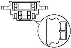
- 2.Install the clutch block as shown.Take note ofthe direction.
Lower casing cover
- 1.Check bearing for rust or rumbling when run.Replace if necessarary.
- Remove bearing and oil seal by bearing puller. Note: Don't remove bearing unless change it.
- Clean casing cover by a soft brush and solvent.
- 4.Check casing cover for crack or damage. Replace if necessary.
Lower casing cover oil seal and bearing installation
- 1.Install oil seal.
- Install bearing.
Note: Please use special tool to install oil seal and bearing. Pay attention to the oil seal installation direction and installation depth. Make sure the manufacturer mark faces toward the reverse gear.
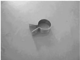
Barrel bearing
Inspect barrel bearing with guard board and barrel bearing without guard board for wear, crack or damage.Replace if necessary.
Drive shaft
Inspect the drive shaft for crank or wear.Replace if necessary.
Gear
Forward gear bearing
Inspect bearing forrust and rumbling when rotating.Replace if necessary.
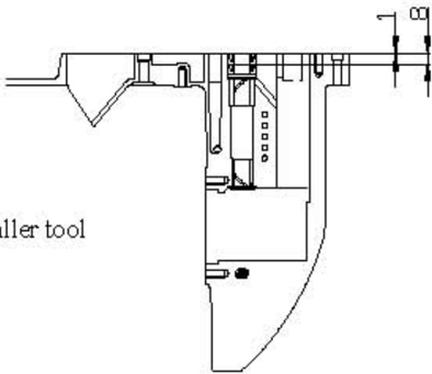
Lower unit casing
- Replace if necessary.
- 2.Install the barrel bearingwith guard board and barrel bearing without guard board by special tool.
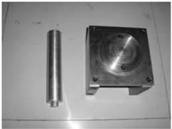
Barrel bearing with guard board installer tool
Lower casing bracket and barrel bearing without guard board installer tool
- 3.Install new oil seal, with the depth as shown. (unit: mm)
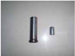
Lower casing bracket and drive shaft oil seal installer tool
| Trouble type | Possible reason | Recovery action |
|---|---|---|
| Starter not operate | Starter | Repair or replace |
| Starter not operate | Shift level is notin neutral | Shift toneutral |
| Engine will not start (starter operates) | Fuel tank is empty | Fill tankwith clean,freshfuel |
| Engine will not start (starter operates) | Fuel filter clogged | Replace fuel filter |
| Engine will not start (starter operates) | Fuel pump has malfunctioned | Repair or replace |
| Engine will not start (starter operates) | Air vent screwnot loosened | Loosen airvent screw |
| Engine will not start (starter operates) | Spark plug(s) fouled or of incorrect type. | Inspect spark plug(s). Clean orreplace withrecommended type |
| Engine will not start (starter operates) | Spark plug cap(s) fitted incorrectly | Check and re-fit cap(s) |
| Engine will not start (starter operates) | Ignition wiring damaged or poorly connected | Check wires for wear or breaks.Tighten all loose connections.Replace worn or broken wires |
| Engine will not start (starter operates) | Ignition parts are faulty | Replace |
| Engine will not start (starter operates) | Engine stop switch lanyard is not attached | Attach lanyard |
| Engine will not start (starter operates) | Engine inner parts are damaged | Repair |
| Engine idles irregularly or stalls | Spark plug(s) fouled or of incorrect type. | Inspect spark plug(s).Clean or replace withrecommended type |
| Engine idles irregularly or stalls | Fuel system is obstructed | Checkfor pinched orkinkedfuel line or other obstructions in fuel system |
| Engine idles irregularly or stalls | Fuel contaminated orstale | Fill tank with clean,freshfuel |
| Engine idles irregularly or stalls | Fuel filter clogged | Replace with recommended type |
| Engine idles irregularly or stalls | Spark plug gap is incorrect | Inspect and adjust as specified |
| Engine idles irregularly or stalls | Ignition wiring damaged or poorly connected | Check wires for wear orbreaks. Tighten all loose connections.Replaceworn orbroken wires |
| Engine idles irregularly or stalls | Specified engine oil is not being used | Check and replace oil as specified |
| Engine idles irregularly or stalls | Thermostat is faulty or clogged | Replace |
| Engine idles irregularly or stalls | Carburetor adjustments areincorrect | Replace |
| Engine idles irregularly or stalls | Fuel pump is damaged | Replace |
| Engine idles irregularly or stalls | Airvent screw onfuel tankis closed | Loosen airvent screw |
| Engine idles irregularly or stalls | Fuel connection is incorrect | Connect correctly |
| Engine idles irregularly or stalls | Choke knob is pulled out | Return to home position |
| Engine idles irregularly or stalls | Motor angle is too high | Return to normal operating position |
| Engine power loss | Propeller is damaged | Repair or replace propeller |
| Engine power loss | Trim angle is incorrect | Adjust trim angle to achieve most efficient operation |
| Engine power loss | Motoris mounted at incorrect transom height | Adjust motor to proper transom height |
| Engine power loss | Boat bottom isfouledwithmarine growth | Clean boat bottom |
| Engine power loss | Weeds or other foreign matter are tangled on gear housing | Removeforeignmatter and clean lower unit |
| Engine power loss | Spark plug(s) are fouled or incorrect type | Inspect spark plug(s).Clean or replace with recommended type |
| Engine power loss | Fuel systemis obstructed | Checkfor pinched or kinked fuel line or other obstructions infuel system |
| Engine power loss | Fuel filter is clogged | Replace with recommended type |
| Engine power loss | Fuel is contaminated or stale | Fill tank with clean,fresh fuel |
| Engine power loss | Spark plug gap is incorrect | Inspect and adjust as specified |
| Engine power loss | Ignition wiring is damaged or poorly connected | Check wires for wear or breaks.Tighten all loose connections.Replace worn orbroken wires |
| Engine power loss | Ignition parts have failed | Replace |
| Engine power loss | Specified engine oil is not being used or oilis added too much | Check andreplace oilas specified,or add engine oil to specified position |
| Engine power loss | Thermostat is faulty | Replace |
| Engine power loss | Fuel pump hasmalfunctioned | Replace |
| Engine power loss | Fuel joint connection is incorrect | Connect correctly |
| Engine power loss | Specified spark plug(s) are not being used | Check and replace spark plug(s) as specified |
| Engine vibrates excessively | Propeller is damaged | Repair or replace propeller |
| Engine vibrates excessively | Propeller shaft is damaged | Replace |
| Engine vibrates excessively | Weeds or other foreignmatter are tangled on propeller | Remove and clean propeller |
| Engine vibrates excessively | Motormountingboltisloose | Tighten bolt |
| Engine vibrates excessively | Steering isloose | Tighten steering pivot |
| Engine vibrates excessively | Steering pivot is damaged | Replace |