Parsun OUTBOARD MOTORS F15BM/BW/FW F9.9BM/BW/FW OWNER'S MANUAL
Table of contents
- 1. Main components and General information
- 2 Operation
- 3. Maintenance
- 3.1 Greasing
- 3.2 Cleaning and adjusting spark plug
- 3.3 Checking the fuel system
- 3.4 Inspecting idling speed
- 3.5 Changing engine oil
- 3.6 Checking wiring and connectors
- 3.7 Checking for leakage
- 3.8 Checking propeller
- 3.9 Changing gear oil
- 3.10 Cleaning fuel tank
- 3.11 Checking and replacing anode(s)
- 3.12 Checking top cowling
- 3.13 Maintenance Table
- 4 Transporting and storing
- 5. Actions in emergency
- 6. Troubleshooting
- Circuit diagram
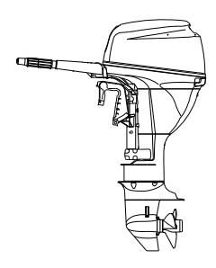
1. Main components and General information
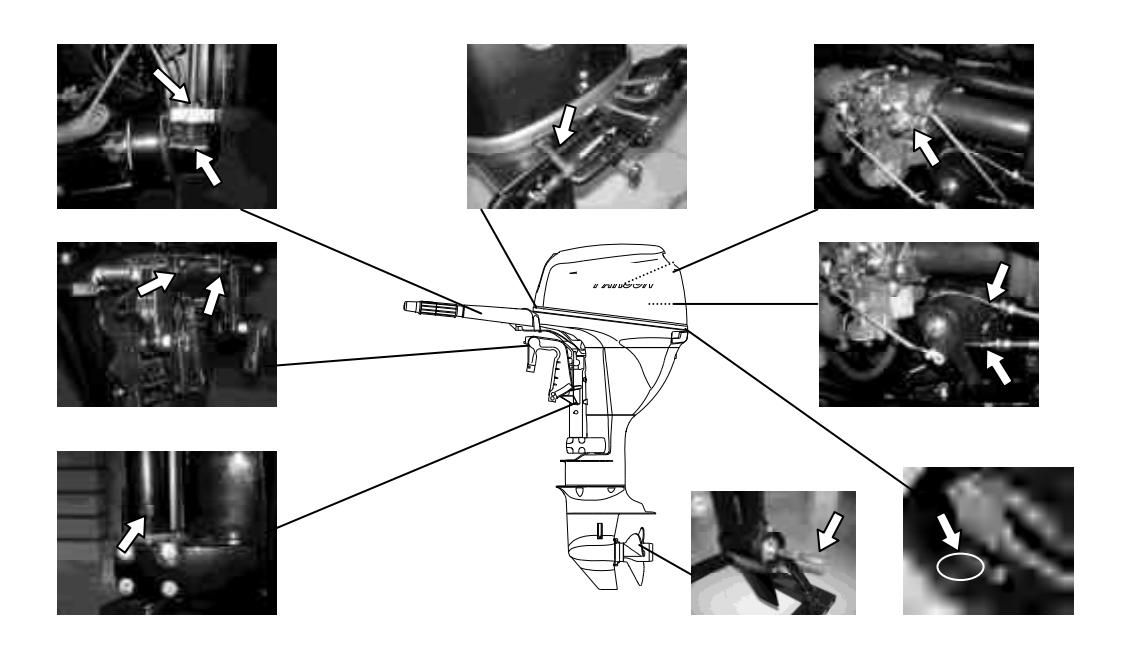
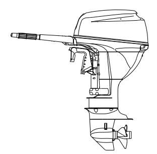
1.1 Main components
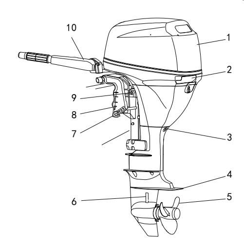
- Top cowling
- Top cowling lock handle
- Drain screw
- Anti-cavitation plate
- Propeller
- Cooling water inlet
- Trim rod
- Clamp bracket
- Steering friction bolt
- Tiller handle
- Starter handle
- Warning indicator(s)
- Gear shift lever
- Engine stop button / Engine stop lanyard switch
- Throttle friction adjuster
- Throttle grip
- Clamp bolt
- Rope attachment
- Tilt support bar
- Fuel joint
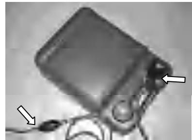
- Fuel tank
A portable fuel tank includes parts as follows:
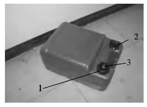
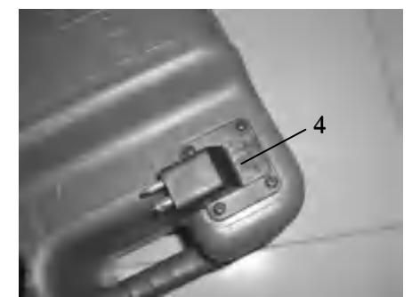

The fuel tank supplier with this engine could only be used as supply of fuel for its running and must not be as a fuel storage container.
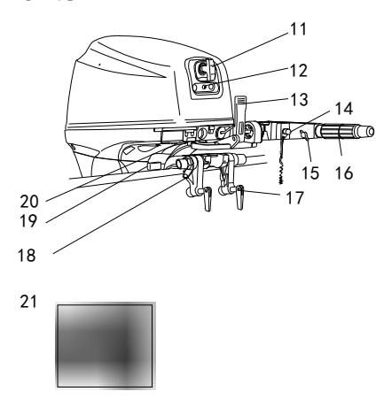
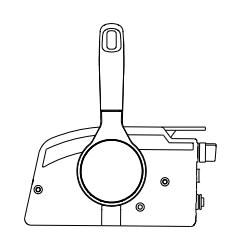
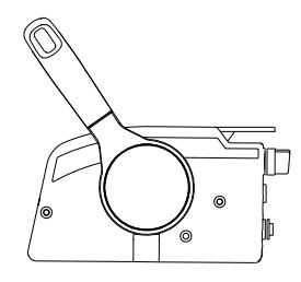
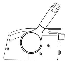
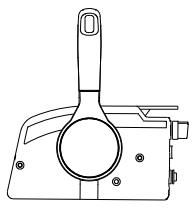
Remote control
The remote control lever actuates both the shifter and the throttle. The electrical switches are mounted on the remote control box.
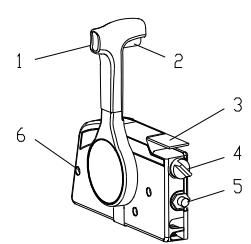
- Remoter control lever
- Neutral interlock trigger
- Neutral throttle lever
- Main switch/choke switch
- Engine stop lanyard switch
- Throttle friction adjuster
Remote control lever
Moving the lever forward from the neutral position engages forward gear. Pulling the lever back from neutral engages reverse. The engine will continue to run at idle until the lever is moved about 35º (a detent can be felt). Moving the lever farther opens the throttle, and the engine will begin to accelerate.
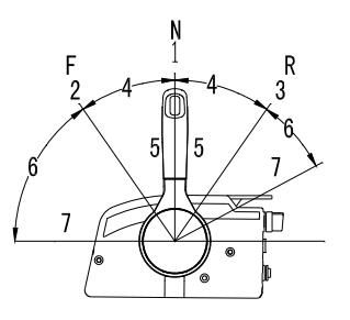
- Neutral "N"
- Forward "F"
- Reverse "R"
- Shift
- Fully closed
- Throttle
- Fully open
Neutral interlock trigger
To shift out of neutral, first pull the neutral interlock trigger up.
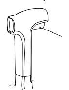
- Neutral interlock trigger
Neutral throttle lever
To open the throttle without shifting into either forward or reverse, put the remote control lever in the neutral position and lift the neutral throttle lever.
NOTE:
The neutral throttle lever will operate only when the remote control lever is in neutral. The remote control lever will operate only when the neutral throttle lever is in the closed position
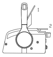
- Fully open
- Fully closed
1.2 General information
1.2.1 Specification
Parameter
| Items | Data | Items | Data |
|---|---|---|---|
| Type of engine | 4-stroke L | Weight (S) | 49Kg |
| Displacement | 323cm 3 | Weight (L) | 51Kg |
| Bore X stroke | 59mm×59mm | Recommended fuel | Unleaded regular gasoline |
| Gear ratio | 2.08 (27/13) | fuel tank capacity | 24L |
| Overall length | 1001mm | Recommended engine oil | SAE10W30 orSAE10W40 |
| Overall width | 427mm | Engine oil quantity | 1.0L |
| Overall height (S) | 1080mm | Recommended gear oil | Hypoid gear oil SAE # 90 |
| Overall height (L) | 1207mm | Gear oil quantity | 250cm 3 |
| Transom height (S) | 381mm | Spark plug | DPR6EA-9 |
| Transom height (L) | 508mm | Spark plug gap | 0.8~0.9mm |
Performance
| Items | data | Items | data | |||
|---|---|---|---|---|---|---|
| Maximum output | 11Kw/5000Rpm(15HP) | Valve clearance IN (cool engine) | 0.15~0.25mm | |||
| 7.3Kw/5000Rpm (9.9HP) | Valve clearance EX (cold engine) | 0.20~0.30mm | ||||
| Full throttle operating range | 4500~5500Rpm | Tightening | Spark plug | 18.0Nm | ||
| Idling speed (in neutral) | speed(in | 950 $\pm$ 50Rpm | torque for engine | Engine oil drain bolt | 28.0Nm |
1.2.2 Fueling instruction
Fueling instructions:
Recommended gasoline: Regular unleaded gasoline,If it is not available, then premium gasoline.
If knocking or pinging occurs, use a different brand of gasoline or premium unleaded fuel. If leaded gasoline is usually used, engine valves and related parts should be inspected after every 100 hours of operation.
WARNING:
- Do not smoke when refueling, and keep away from sparks, flames, or other sources of ignition.
- Stop engine before refueling.
- Refuel in a well-ventilated area; refuel portable fuel tanks off the boat.
- Do not overfill the fuel tank.
- Take care not to spill gasoline, if gasoline spills, wipe it up immediately.
- Tighten the filler cap securely after refueling.
- If you should swallow some gasoline, inhale gasoline vapor, or get gasoline in your eye, get immediate medical attention.
- If any gasoline spills onto your skin, immediately wash with soap and water. Change clothing if gasoline spill s on it.
- Touch the fuel nozzle to metal components to prevent electrostatic sparks.
CAUTION:
Use only new clean gasoline which has been stored in clean containers and is not contaminated with water or foreign matter.
Engine oil:
Recommended engine oil: 4-stroke outboard motor oil SAE10W30 and SAE10W40 (1.0L).
WARNING:
- Do not start the engine when the oil level is low. Serious damage might occur.
- Always check the oil level before starting the engine.
CAUTION:
All 4-stroke engines are shipped from the factory without engine oil.
1.2.3 Propeller selection
The performance of your outboard motor will be critically affected by your choice of propeller, as an incorrect choice could adversely affect performance. The outboard motor is fitted with propeller chosen to perform well over a range of applications, but there may be uses where a propeller with a different pitch would be more appropriate. "PARSUN" dealers stock a range of propellers and can advise you and install a propeller on your outboard that is best suited to your application.
For a greater boat load and a low engine speed, a smaller-pitch propeller is more suitable. Conversely, a large-pitch propeller is more suitable for a smaller operating load as it enables the correct engine speed to be maintained.
2 Operation
2.1 Installation
Mount the outboard motor on the center line (keel line) of the boat. For boats without a keel or which are asymmetrical, consult your dealer.
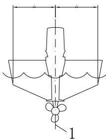
1.Center line (keel line)
NOTE:
During water testing check the buoyancy of the boat, at rest, with its maximum load. Check that the static water level on the exhaust housing is low enough to prevent water entry into the power head, when water rises due to waves when the outboard is not running.
WARNING:
- Overpowering a boat could cause severe instability. Do not install an outboard motor with more horsepower than the maximum rating on the capacity plate of the boat. If the boat does not have a capacity plate, consult the boat manufacturer.
- Improper mounting of the outboard motor could result in dangerous conditions and injury.
- Your dealer or other person experienced in proper rigging should mount the motor. If you are mounting the motor yourself, you should be trained by an experienced person.
- The information presented in this section is intended as reference only. Proper mounting depends in part on experience and the specific boat and motor combination.
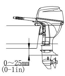
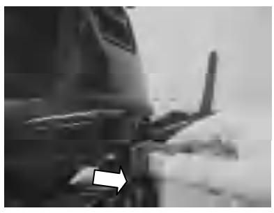
2.1.1 Mounting height
The mounting height of the outboard motor greatly affects your boat running efficiency. If the mounting height is too high, cavitation tends to occur, thus reducing the propulsion. If the mounting height is too low, the water resistance will increase and thereby reduce engine efficiency. Mount the outboard motor so that the anti-cavitation plate is between the bottom of the boat and a level 25mm below it.
NOTE:
The optimum mounting height of the outboard motor is affected by the boat and motor combination and the desired use. Test runs at a different height can help determine the optimum mounting height. For further information, consult your "PARSUN" dealer or boat manufacturer.
2.1.2 Clamping the outboard motor
- Tighten the transom clamp screw evenly and securely. Occasionally check the clamp screws for tightness during operation of the outboard motor because they could become loose due to engine vibration.
CAUTION:
Outboards that use clamp bracket screws alone are INSUFFICIENT to properly and safely secure the outboard to the Transom. Proper installation of the outboard includes bolting the engine to the boat through the transom.
WARNING:
Loose clamp screws could allow the outboard motor to fall off or move on the transom. This could cause loss of control. Make sure the clamp screws are tightened securely, occasionally check the screws for tightness during operation.
- If the engine restraint cable attachment is equipped on your engine, an engine restraint cable or chain should be used. Attach to a secure mounting point on the boat to avoid the engine being completely lost if it accidentally falls off the transom.

- Secure the clamp bracket to the transom using the appropriate bolts. For details, consult your "PARSUN"dealer.
WARNING:
Avoid using bolts, nuts or washers inappropriate. After tightening, test run the engine and check their tightness.
2.2 Breaking in engine
Your new engine requires a period of breaking to allow mating surfaces of moving parts to wear in evenly.
CAUTION:
Failure to follow the break-in procedure could result in reduced engine life or even severe engine damage.
1.For the first hour of operation:
Run the engine at 2000r/min or at approximately half throttle.
2.For the second hour of operation:
Run the engine at 3000r/min or at approximately three-quarter throttle.
3.For the next eight hours of operation:
Avoid continuous operation at full throttle for more than five minutes at a time.
- Operate the engine normally.
2.3 Pre-operation checks
Fuel
- Check to be sure you have plenty of fuel for your trip.
- Make sure there are no fuel leaks or gasoline fumes.
- Check fuel line connections to be sure they are tight
- Be sure the fuel tank is positioned on a secure, flat surface, and that the fuel line is not twisted or flattened, or likely to contact sharp objects.
Controls
- Check throttle, shift and steering for proper operation before starting the engine.
- The controls should work smoothly, without binding or unusual free play.
- Look for loose or damaged connections.
- Check operation of the starter and stop switches when the outboard motor is in the water.
CAUTION:
- Do not start the engine out of water. Overheating and serious engine damage can occur.
- Check the engine and engine mounting.
- Look for loose or damaged fasteners.
- Check the propeller for damage.
Checking the engine oil level
- Put the outboard motor in an upright position (not tilted).
- Check the oil level using the dipstick to be sure the level falls between the upper and lower marks. Fill with oil if it is below the lower mark, or drain to the specified level if it is above the upper mark.
- Upper level mark
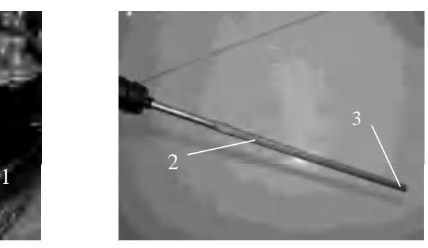
Oil dipstick 3. Lower level mark
CAUTION:
Be sure to completely insert the dipstick into the dipstick guide.
2.4 Filling fuel
WARNING:
Gasoline and its vapors are highly flammable and explosive. Keep away from sparks, cigarettes, flames, or other sources of ignition.
- Remove the fuel tank cap.
- Carefully fill the fuel tank.
- Securely close the cap after filling the tank. Wipe up any spilled fuel.
2.5 Starting engine
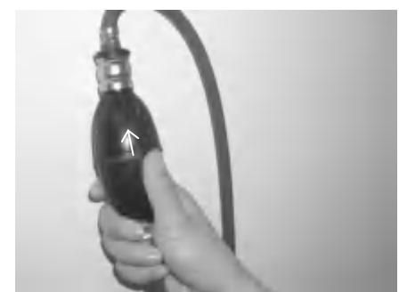
For F15/9.9BM
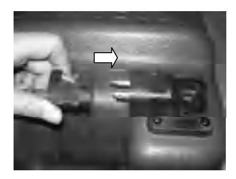
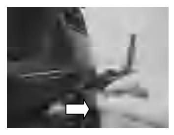
- Connect fuel joints securely and squeeze the primer pump with the outlet end up until you feel it becomes firm (if equipped with a fuel joint).
- Place the gear shift lever in neutral.
NOTE:
The start-in-gear protection device prevents the engine from starting except when in neutral. Attach the engine stop switch lanyard to secure place on your clothing, or your arm or leg. Then install the lock plate on the other end of the lanyard into the engine stop switch.
WARNING:
- The engine must be started in neutral, otherwise damage to the engine can occur.
- Do not attach the lanyard to clothing that could tear loose. Do not route the lanyard where it could become entangled and preventing it from functioning.
- Avoid accidentally pulling the lanyard during normal operation. Loss of engine power means the loss of steering control. Also, without engine power, the boat could slow rapidly. This could cause people and objects in the boat to be thrown forward.

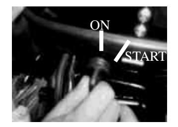
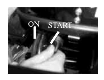
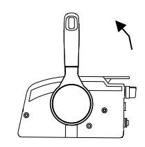
- Place the throttle grip in the "START" (start) position.
- Pull out the choke knob fully.
- Choke knob
NOTE:
- It is not necessary to use the choke when starting a warm engine.
- If the choke is left the home position while the engine is running, the engine will run poorly or stall.
- 6. Pull the manual starter handle slowly until you feel resistance. Then give a strong pull straight to crank and start the engine. Repeat if necessary.
- After the engine starts, slowly return the manual starter handle to its original position before releasing it.
- Slowly return the throttle grip to the fully closed position.
CAUTION:
- When the engine is cold, it needs to be warmed up.
- If the engine does not start on the first try, repeat the procedure. If the engine fails to start after 4 or 5 tries, open the throttle a small amount (between 1/8 and 1/4), and try again.
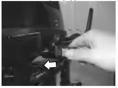
For F15/9.9BW
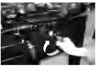
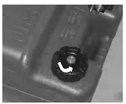
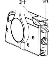
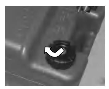
- Loosen the air vent screw on the fuel tank cap, 2 or 3 turns.
- Place the gear shift lever in neutral.

WARNING:
The engine must be started in neutral otherwise damage to the starter can occur.
- Do not attach the lanyard to clothing that could tear loose. Do not route the lanyard where it could become entangled, preventing it from functioning.
- Avoid accidentally pulling the lanyard during normal operation. Loss of engine power means the loss of steering control. Also, without engine power, the boat could slow rapidly. This could cause people and objects in the boat to be thrown forward.
NOTE:
The start-in-gear protection device prevents the engine from starting except when in neutral. Attach the engine stop switch lanyard to secure place on your clothing, or your arm or leg. Then install the lock plate on the other end of the lanyard into the engine stop switch.

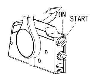
- Place the throttle grip in the "START" (start) position. Turn the main switch to "ON"(on).
- Press in and hold the main switch to operate the remote choke system. Turn the main switch to "START" (start), and hold it for a maximum or 5 seconds
- 6.After the engine starts, slowly return the manual starter handle to its original position before releasing it. Immediately after the engine starts, release the main switch and allow it to return to "ON" (on).
- 7.Slowly return the throttle grip to the fully closed position.
NOTE:
- Never turn the main switch to "START"(start)while the engine is running.
- Do not keep the starter motor turning for more than 5 seconds. If the starter motor is turned continuously for more than 5 seconds, the battery will be quickly discharged, thus making it impossible to start the engine. The starter can also be damaged. If the engine will not start after 5 seconds of cranking, return the main switch to "ON"(on), wait 10 seconds, then crank the engine again.
- When the engine is cold, it needs to be warmed up.
- If engine does not start on the first try, repeat the procedure. If the engine fails to start after 4 or 5 tries, open the throttle a small amount (between 1/8 and 1/4), and try again.
For F15/9.9W
- Place the remote control lever in neutral.
NOTE:
The start-in-gear protection device prevents the engine from starting except when in neutral.
- Attach the engine stop switch lanyard to a secure place on your clothing, or your arm or leg. Then install the lock plate on the other end of the lanyard into the engine stop switch.
WARNING:
- Attach the engine stop switch lanyard to a secure place on your clothing, or your arm or leg.
- Do not attach the lanyard to clothing that could tear loose. Do not route the lanyard where it could become entangled and preventing it from functioning.
- Avoid accidentally pulling the lanyard during normal operation. Loss of engine power means the loss of steering control. Also, without engine power, the boat could slow rapidly. This could cause people and objects in the boat to be thrown forward.
- 3. Turn the main switch to "ON" (on).
- Open the throttle slightly without shifting using the neutral throttle lever or free accelerator. You may need to change the throttle opening slightly depending on engine temperature. After the engine starts, return the throttle to the original position.
NOTE:
- On remote controls equipped with a neutral throttle lever, a good starting point is to lift the lever just until you feel resistance, then lift slightly more.
- The neutral throttle lever or free accelerator can only be used when the remote control lever is in neutral.
- 5. Press in and hold the main switch to operate the remote choke system. The remote chock switch automatically returns to its normal position when release your hand. Therefore keep the switch pressed in.
NOTE:
- It is not necessary to use the choke when starting a warm engine.
- If the choke is left the home position while the engine is running, the engine will run poorly or stall.
- Turn the main switch to "START" (start), and hold it for a maximum or 5 seconds.
- Immediately after the engine starts, release the main switch and allow it to return to "ON"(on).
CAUTION:
- Never turn the main switch to "START" (start) while the engine is running.
- Do not keep the starter motor turning for more than 5 seconds. If the starter motor is turned continuously for more than 5 seconds, the battery will be quickly discharged, thus making it impossible to start the engine. The starter can also be damaged. If the engine will not start after 5 seconds of cranking, return the main switch to "ON"(on), wait 10 seconds, then crank the engine again.
NOTE:
When the engine is cold, it needs to be warmed up.
2.6 Warm up engine
- After starting the engine, place the gear shift lever in neutral. For approximately the first 3 minutes after starting, warm up the engine by operating at one fifth throttle or less. Otherwise, it will shorten engine life.
CAUTION:
- If the choke knob is left pulled out after the engine starts, the engine will stall.
- In the temperatures of -5℃ or less, leave the choke knob pulled out fully for approximately 30 seconds after starting.
- Check for steady flow of water from the cooling water pilot hole.
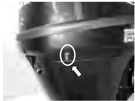
CAUTION:
If water is not flowing out of the hole at all times while the engine is running, stop the engine and check whether the cooling water inlet on the lower case or the cooling water pilot hole is blocked.
If the problem cannot be located and corrected, consult your PARSUN dealer.
2.7 Shifting
WARNING:
Before shifting, make sure there are no swimmers or obstacles in the water near you.
CAUTION:
To shift from forward to reverse or vice versa, first close the throttle so that the engine idles (or runs at low speeds).
2.7.1 Forward
1.Place the throttle grip in the fully closed position.
- Move the gear shift lever quickly and firmly from neutral to forward.
For F15/9.9FW
Pull up the neutral interlock rigger and move the remote control lever quickly and firmly from neutral to forward.
2.7.2 Reverse
WARNING:
When operating in reverse, go slowly. Do not open the throttle more than half. Otherwise the boat could become unstable, which could result in loss of control and an accident.
- Place the throttle trip in the fully closed position.

- Move the gear shift lever quickly and firmly from neutral to reverse.
For F15/9.9FW
- Check that the tilt lock lever is in the lock position.
- Pull up the neutral interlock rigger and move the remote control lever quickly and firmly from neutral to reverse.
2.8 Tiller
- Change direction.
To change direction, move the tiller handle to the left or right as necessary.
- Change speed.
Turn the grip counterclockwise to increase speed and clockwise to decrease speed.
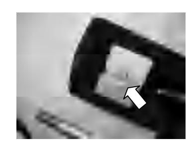
- Throttle indicator.
The throttle indicator is on the throttle grip. The fuel consumption curve on the throttle indicator shows the relative amount of fuel consumed for each throttle position. Choose the setting that offers the best performance and fuel economy for the desired operation.
- Throttle indicator
- Throttle friction adjuster
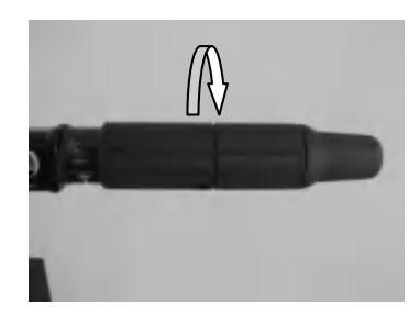
The throttle friction adjuster is on the tiller handle, which provides adjustable resistance to movement of the throttle grip, and can be set according to operator preference.
To increase resistance, turn the adjuster clockwise. To decrease resistance, turn the adjuster counterclockwise. When constant speed is desired, tighten the adjuster to maintain the desired throttle setting.
WARNING:
Do not over-tighten the friction adjuster. If there is too much resistance, it could be difficult to move throttle lever or grip, which could result in an accident.
2.9 Stopping engine
NOTE:
Before stopping the engine, first let it cool off for a few minutes at idle or low speed. Stopping the engine immediately after operating at high speed is not recommended.
- Push and hold the engine stop button until the engine comes to a complete stop.
NOTE:
If the outboard motor is equipped with an engine stop switch lanyard, the engine can also be stopped by pulling the lanyard and removing the lock plate from the engine stop switch.
- Tighten the air vent screw on the fuel tank cap.
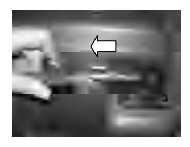
3.Disconnect the fuel line.

- Turn the main switch to "OFF" (off).
- Tighten the air vent screw on the fuel tank cap.
3.Disconnect the fuel line.
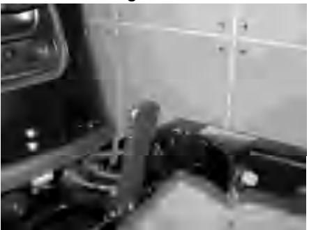
2.10 Trimming outboard motor
There are 4 or 5 holes provided in the clamp bracket to adjust the outboard motor trim angle.
- Stop the engine.
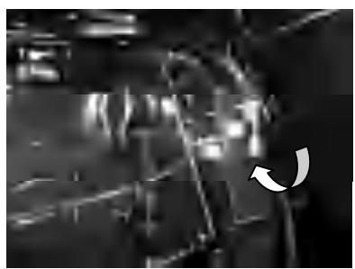
- Remove the trim rod from the clamp bracket while slightly tilting the outboard motor up.
- Reposition the rod in the desired hole. Make test runs with the trim set to different angles to find the position that works best for your boat and operating conditions.
WARNING:
- Stop the engine before adjusting the trim angle.
- Use care to avoid being pinched when removing or installing the rod.
- Use caution when trying a trim position for the first time. Increase speed gradually and watch for any signs of instability or control problems. Improper trim angle can cause loss of control.
2.11 Tilting up and down
If the engine will be stopped for some time or if the boat is moored in shallows, the outboard motor should be tilted up to protect the propeller and casing from damaged by collision with obstructions, and also to reduce corrosion.
WARNING:
Be sure all people are clear of the outboard motor when tilting up and down, also be careful not to pinch any body parts between the drive unit and engine bracket.
NOTE:
- Do not tilt up the engine by pushing the tiller handle because this could break the handle.
- The outboard motor cannot be tilted when in reverse.
2.11.1 Tilting up
- Place the gear shift lever in neutral (if equipped).
- Tighten the steering friction adjuster by turning it clockwise to prevent the motor from turning freely.
- Disconnect the fuel line from the outboard motor.
- Place the tilt lock lever(if equipped) in the up position.
- Hold the rear handle and tilt the engine up fully until the tilt support lever automatically locks.
For F15/9.9FW
- Place the remoter control lever in neutral (if equipped).
- Disconnect the fuel line from the outboard motor.
- Place the tilt lock lever (if equipped) in the up position.
- Hold the rear handle and tilt the engine up fully until the tilt support lever automatically locks.
2.11.2 Tilting down
- Slightly tilt the outboard motor up.
- Slowly tilt the outboard motor down while place the tilt lock lever in the down position.
- Loose the steering friction adjuster by turning it counterclockwise, and adjust the steering friction according to operator preference.
WARNING:
If there is too much resistance it could be difficult to steer, which could result in an accident.
2.12 Cruising in other conditions
2.12.1 Cruising in shallow water
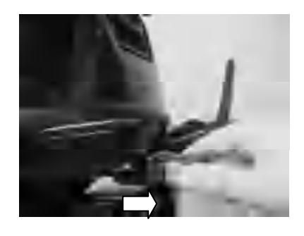
The outboard motor can be tilted up partially to allow operation in shallow water.
WARNING:
- Be sure to place the gear shift in neutral before cruising in shallow water or while tilting up the outboard motor.
- Return the outboard motor to its normal position as soon as the boat is back in deeper water.
CAUTION:
The cooling water inlet on the lower unit should be not above the surface of the water when setting up for and cruising in shallow water. Otherwise severe damage from overheating can result. For tilting procedure, see section 2.11.
2.12.2 Cruising in salt water
After operating in salt water, wash out the cooling water passages with fresh water to prevent them from becoming clogged with salt deposits.
3. Maintenance
While using the outboard motor, the periodic maintenance is necessary for you to ensure its performance.
WARNING:
Be sure to turn off the engine when you perform maintenance unless otherwise specified. This work should always be done by a qualified mechanic or your authorized Parsun dealer.
CAUTION:
If replacement parts are necessary, use only genuine PARSUN parts or appropriate parts of the same type and quality.
3.1 Greasing
3.2 Cleaning and adjusting spark plug
You should periodically remove and inspect the spark plug because heat and deposits will cause the spark plug to slowly break down and erode. If necessary, you should replace the spark plug with another of the correct type.
Before fitting the spark plug, measure the electrode gap with a wire thickness gauge; adjust the gap to specification if necessary.
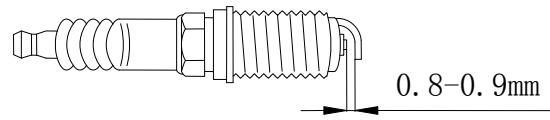
When fitting the plug, always clean the gasket surface and use a new gasket. Wipe off any dirt from the threads and screw in the spark plug to the correct torque.
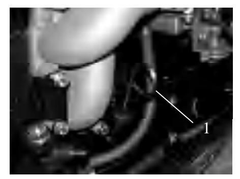
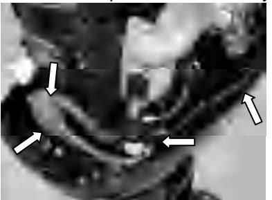
3.3 Checking the fuel system
- Check the fuel lines for leaks, crack, or malfunction. If a problem is found, contact your PARSUN dealer and have this repaired immediately.
WARNING:
- Check for fuel leakage regularly.
- If any fuel leakage is found, the fuel system must be repaired by a qualified mechanic.
- Check the fuel filter periodically. If foreign matter is found in the filter, clean it.

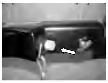
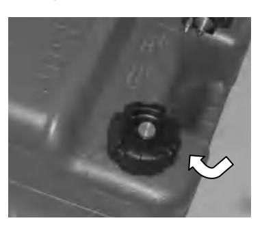
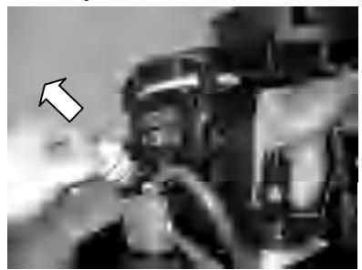
3.3.1 Cleaning the fuel filter
- Removing the nut holding the fuel filter assembly if equipped.
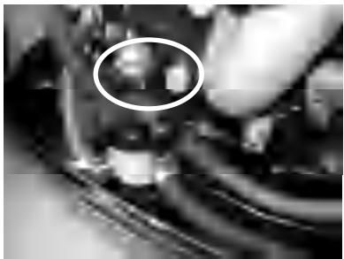
- Unscrew the filter cup, catching any spilled fuel in a rag.
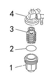
- filter cup 2. O-ring 3.filter element 4. filter housing
- Reinstall the filter element in the cup. Make sure the O-ring is in position in the cup. Firmly screw the cup onto the filter housing.
- Attach the filter assembly to the bracket so that the fuel hoses are attached to the filter assembly. Run the engine and check the filter and lines for leaks.
3.4 Inspecting idling speed
A diagnostic tachometer should be used for this procedure. Results may vary depending on whether testing is conducted with the flushing attachment, in a test tank, or with the outboard motor in the water.
- Start the engine and allow it to warm up fully in neutral until it is running smoothly.
- Verify whether the idle speed is set to specification. Idle speed:950±50Rpm
CAUTION:
Correct idling speed inspection is only possible if the engine is fully warmed up. If not warmed up fully, the idle speed will measure higher than normal. If you have difficulty verifying the idle peed, or the idle speed requires adjustment, consult a PARSUN dealer or other qualified mechanic.
3.5 Changing engine oil
WARNING:
- Avoid draining the engine oil immediately after stopping the engine. The oil is hot and should be handled with care to avoid burns.
- Be sure the outboard motor is securely fastened to the transom or a stable stand.
CAUTION:
- Change the engine oil after the first 10 hours of operation, and every 100 hours or at 6-month intervals thereafter. Otherwise the engine will wear quickly.
- Change the engine oil when the oil is still warm.
- Put the outboard motor in an upright position (not tilted).
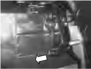
- Prepare a suitable container that holds a larger amount than the engine oil capacity. Loosen and remove the drain screw while holding the container under the drain hole. Then remove the oil filler cap. Let oil drain completely. Wipe up any spilled oil immediately.

- Put a new gasket on the oil drain screw. Tighten the drain screw.
- Add the correct amount of oil through the filler hole. Install the filler cap.
- Start the engine and make sure that there are no oil leaks.
- Turn off the engine and wait 3 minutes. Recheck the oil level using the dipstick to be sure the level falls between the upper and lower marks.
CAUTION:
The oil should be changed more often when the engine is operated under adverse conditions such as extended trolling.
3.6 Checking wiring and connectors
Check that each grounding wire is properly secured and each connector is engaged securely.
3.7 Checking for leakage
Check that no exhaust or water leaks from the joints between the exhaust cover, cylinder head, and body cylinder.
Check for oil leaks around the engine.
CAUTION:
If any leaks are found, consult your PARSUN dealer.
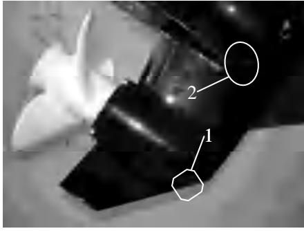
3.8 Checking propeller
WARNING:
- Before inspecting, removing or installing the propeller, always take actions to ensure the engine does not accidentally start, such as removing the spark plug caps from the spark plugs, placing the shift control in neutral, and removing the lanyard from the engine stop switch, etc.. Serious injury can occur if the engine should start and you are standing too close to the propeller.
- Do not use your hand to hold the propeller when loosening or tightening the propeller nut. Put a wood block between the anti-cavitation plate and the propeller to prevent the propeller from turning.

- Check each of the propeller blades for wear, erosion from cavitation or ventilation, or other damage.
- Check the propeller shaft for damage.
- Check the splines/shear pin for wear or damage.
- Check for fish line tangled around the propeller shaft.
- Check for the propeller shaft oil seal for damage.
3.8.1 Removing the propeller
- Straighten the cotter pin and pull it out using a pair of pliers.
- Remove the propeller nut, washer, and spacer (if equipped).
- Remove the propeller and thrust washer.
3.8.2 Installing the propeller
CAUTION:
- Be sure to install the thrust washer before instating the propeller, otherwise the lower case and propeller boss could be damaged.
- Be sure to use a new cotter pin and bend the ends over securely. Otherwise the propeller could come off during operation and be lost.
- Apply a marine grease or corrosion resistant grease to the propeller shaft.
- Install the spacer (if equipped), thrust washer, and propeller on the propeller shaft.
- Install the spacer (if equipped) and the washer.
- Tighten the propeller nut. Align the propeller nut with the propeller shaft hole. Insert a new cotter pin in the hole and bend the cotter pin ends.
3.9 Changing gear oil
WARNING:
- Be sure the outboard motor is securely fastened to the transom or a stable stand.
- Never get under the lower unit while the outboard motor is tilted, even when the tilt support lever or knob is locked. Serious injury could occur if the motor falls.
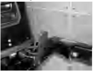
- Tilt the outboard motor so that the gear oil drain screw is at the lowest point possible.
- Place a suitable container under the gear case.
- Remove gear oil drain screw.
1.Gear oil drain screw 2.Oil level plug
CAUTION:
Change the gear oil after the first 10 hours of operation, and every 100 hours or at 6-month intervals thereafter. Otherwise the gear will wear quickly.
- Remove the oil level plug to allow the oil to drain completely.
CAUTION:
Inspect the used oil after it has been drained. If the oil is milky, water is getting into the gear case which can cause gear damage. Consult your PARSUN dealer.
- Use a flexible or pressurized filling device; inject the gear oil into the gear oil drain screw hole. (250cm3)
- When the oil begins to flow out of the oil level plug hole, insert and tighten the oil level plug (If necessary, change the seal spacer).
- Insert and tighten the gear oil drain screw (If necessary, change the seal spacer).
3.10 Cleaning fuel tank
WARNING:
- Keep away from sparks, cigarettes, flames, or other sources of ignition when cleaning the fuel tank.
- Cleaning the fuel tank in a well-ventilated open air.
- Pour a small amount of suitable solvent into the tank. Install the cap and shake the tank. Drain the solvent completely. Empty the fuel tank into an approved container.
- Pour a small amount of suitable solvent into the tank. Install the cap and shake the tank. Drain the solvent completely.
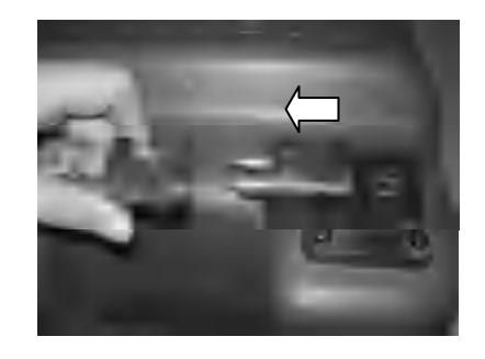
- Pull the fuel joint assembly out of the tank.
- Clean the filter in a suitable cleaning solvent and allow it to dry.
- Replace the gasket with a new one. Reinstall the fuel joint assembly and tighten the screws firmly.
3.11 Checking and replacing anode(s)
Inspect the external anodes periodically. Remove scales from the surfaces of the anodes. Consult a PARSUN dealer for replacement of external anodes.
CAUTION:
Do not paint anodes, as this would render them ineffective and can cause more rapid engine corrosion.
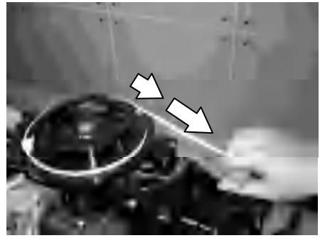
3.12 Checking top cowling
Check the fitting of the top cowling by pushing it with both hands. If it is loose have it repaired by your PARSUN dealer.

3.13 Maintenance Table
When utilized under normal condition, maintained and repaired in the proper manner, the motor can work normally within the normal life period.
Frequency of maintenance operations may be adjusted according to the operating conditions, but the following table gives general guidelines.
The "●" symbol indicates the check-ups which you may carry out by yourself.
The "○" symbol indicates work to be carried out by your Parsun dealer.
| Item | Operations | Initial 10 hours (1 month) | Initial 50 hours (3 months) | Every 100 hours (6 months) | Every 200 hours (1 year) |
|---|---|---|---|---|---|
| Anode(s) (external) | Check/replacement | ● / ○ | ● / ○ | ||
| Anode(s) (internal) | Check/replacement | ○ | |||
| Cooling water passages | Cleaning | ● | ● | ||
| Cowling clamp | Check | ● | |||
| Fuel filter (disposable) | Check/cleaning | ● | ● | ● | |
| Fuel system | Check | ● | ● | ● | |
| Fuel tank (portable tank) | Check/cleaning | ● | |||
| Gear oil | Change | ● | ● | ||
| Greasing points | Greasing | ● | |||
| Idling speed (carburetor model) | Check/adjustment | ● / ○ | ● / ○ | ||
| Propeller and cotter pin | Check/replacement | ● | ● | ||
| Shift link/shift cable | Check/adjustment | ○ |
Continuation
| Item | Operations | Initial 10 hours (1 month) | Initial 50 hours (3 months) | Every 100 hours (6 months) | Every 200 hours (1 year) |
|---|---|---|---|---|---|
| Thermostat | Check | ○ | |||
| Throttle link & cable / Throttle pick-up timing | Check/adjustment | ○ | |||
| Water pump | Check | ○ | |||
| Engine oil | Check/replacement | ● | ● | ||
| Oil filter | Change | ○ | |||
| Spark plug (s) | Cleaning/adjustment /replacement | ● | ● | ||
| Timing belt | Check/replacement | ○ | ○ | ||
| Valve clearance | Check/adjustment | ○ | ○ |
NOTE:
When operating in salt water, turbid or muddy water, the engine should be flushed with clean water after every use.
4 Transporting and storing
4.1 Transporting
The outboard motor should be trailed and stored in the normal running position. If there is insufficient road clearance in this position, then trailer the outboard motor in the tilt position using a motor support device.
CAUTION:
Do not use the tilt support lever or knob when trailering the boat. The outboard motor could shake loose from the tilt support and fall.
WARNING:
- Never get under the lower unit while it is tilted, even if a motor support bar is used.
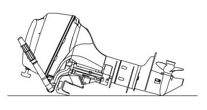
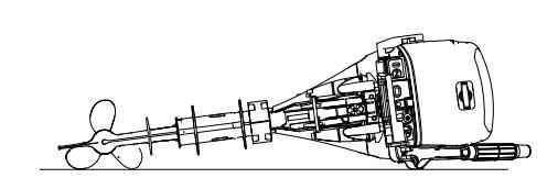
- When transporting or storing the outboard motor while removed from a boat, keep the outboard in the position shown.
CAUTION:
- Place a towel or something similar under the outboard motor to protect it from damage.
- Do not place the outboard motor on its side before drain the engine oil completely, otherwise the oil would enter the cylinder and cause engine trouble.
4.2 Storing
When storing your PARSUN outboard motor for prolonged periods of time (2 months or longer), several important procedures must be performed to prevent damage.
It is advisable to have your outboard motor serviced by an authorized PARSUN dealer prior to storage. However, you, the owner, with a minimum of tools, can perform the following procedures.
CAUTION:
- Keep the outboard motor in an upright attitude when transporting and storing it. If storing or transporting the outboard motor on its side (not upright), put it on a cushion after draining the engine oil completely.
- Do not place the outboard motor on its side before the cooling water has drained from it completely.
- Store the outboard motor in a dry, well-ventilated place, not in direct sunlight.
- Wash the outboard motor body using fresh water.
- Disconnect the fuel line and tighten the air vent screw,
- Remove the engine top cowling and silencer cover
- Install the outboard motor on the test tank.

- Lowest water level
- Fill the tank with fresh water to above the level of the anti-cavitation plate.
CAUTION:
If the fresh water level is below the level of the anti-cavitation plate, or if the water supply is insufficient, engine seizure may occur.
- Start the engine. Flush the cooling system. Perform the flushing and fogging at the same time, as fogging/lubricating of the engine is mandatory to prevent engine rust.
WARNING:
- Do not touch or remove electrical parts when starting or during the operation.
- Keep hands, hair, and clothes away from the flywheel and other rotating parts while the engine is running.
- 7. Run the engine at a fast idle for a few minutes in neutral position.
- Just prior to turning off the engine, quickly spray "Fogging Oil" alternately into each carburetor or the fogging hole of the silencer cover, if equipped.
- If "Fogging Oil" is not available, run the engine at a fast idle until the fuel system empties and the engine stops.
- If "Fogging Oil" is not available, remove the spark plug(s). Pour a teaspoonful of clean engine oil into each cylinder. Crank several times manually. Replace the spark plug(s).
CAUTION:
Store the fuel tank in a dry, well-ventilated place, not in direct sunlight.
5. Actions in emergency
5.1 Impact damage
If the outboard motor hits an object in the water, follow the procedure below.
- Stop the engine immediately.
- Inspect the control system and all components for damage.
- Whether damage is found or not, return to the nearest harbor slowly and carefully.
- Have a PARSUN dealer inspect the outboard motor before operating it again.
5.2 Starter will not operate
If the starter mechanism does not operate, the engine can be started with an emergency starter rope.
WARNING:
- Use this procedure only in an emergency and only to return to port for repairs.
- When the emergency starter rope is used to start the engine, the start-in-gear protection device does not operate. Make sure the remote control lever is in neutral.
- Be sure no one is standing behind you when pulling the starter rope. It could whip behind you and injure someone.
- Do not install the starter mechanism or top cowling after engine is running. Keep loose
clothing and other objects away when starting the engine. Do not touch the flywheel or other moving parts when the engine is running.
Do not touch the ignition coil, spark plug wire, spark plug cap, or other electrical components when starting or operating the motor.
Procedure is as follows:
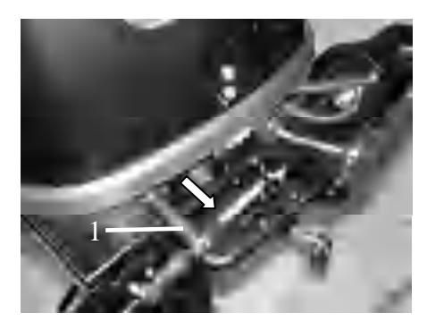
- Remove the top cowling.
- Remove the start-in-gear protection cable and the choke cable.
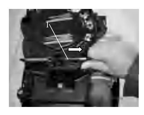
- Start-in-gear protection cable
3.Remove the starter after removing the three bolts.
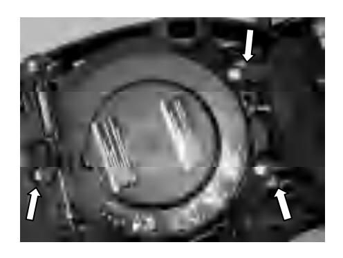
- Prepare the engine for starting. For further information, see section 2.5.
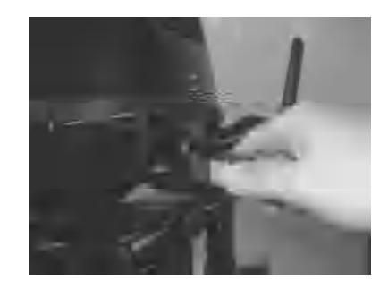
- Insert the knotted end of the emergency starter rope into the notch in the flywheel rotor and wind the rope several turns around the flywheel clockwise.
- Pull the rope slowly until resistance is felt.
- Give a strong pull straight out to crank and start the engine. Repeat it necessary.
5.3 Treatment of submerged motor
If the outboard is submerged, immediately take it to a PARSUN dealer. Otherwise some corrosion may begin almost immediately.
- Thoroughly wash away contaminants with fresh water.
- Remove the spark plug(s), then face the spark plug hole downward to allow any mud, or contaminants to drain.
- Drain the fuel from the carburetor, fuel filter, and fuel line. Drain the engine oil completely.
- Fill the sump with fresh engine oil.
- Feed engine fogging oil or engine oil through the carburetor(s) and spark plug holes while starting the engine.
- Take the outboard motor to a PARSUN dealer as soon as possible.
CAUTION:
Do not attempt to run the outboard motor until it has been completely inspected.
6. Troubleshooting
| Trouble type | Possible reason | Recovery action |
|---|---|---|
| Starter will not operate | Starter components are faulty | Have serviced by your dealer |
| Starter will not operate | Shift level is not in neutral | Shift to neutral |
| Engine will not start (starter operates) | Fuel tank is empty | Fill tank with clean, fresh fuel |
| Engine will not start (starter operates) | Fuel is contaminated or stale | Fill tank with clean, fresh fuel |
| Engine will not start (starter operates) | Fuel filter clogged | Clean or replace with recommended type |
| Engine will not start (starter operates) | Fuel pump has malfunctioned | Have serviced by your dealer |
| Engine will not start (starter operates) | Spark plug(s) fouled or of incorrect type | Inspect spark plug(s). Clean or replace with recommended type |
| Engine will not start (starter operates) | Spark plug cap(s) fitted incorrectly | Check and re-fit cap(s) |
| Engine will not start (starter operates) | Ignition wiring damaged or poorly connected | Check wires for wear or breaks. Tighten all loose connections. Replace worn or broken wires |
| Engine will not start (starter operates) | Ignition parts are faulty | Have serviced by your dealer |
| Engine will not start (starter operates) | Engine stop switch lanyard is not attached | Attach lanyard |
| Engine will not start (starter operates) | Engine inner parts are damaged | Have serviced by your dealer |
| Engine idles irregularly or stalls | Spark plug(s) fouled or of incorrect type | Inspect spark plug(s). Clean or replace with recommended type |
| Engine idles irregularly or stalls | Fuel system is obstructed | Check for pinched or kinked fuel line or other obstructions in fuel system |
| Engine idles irregularly or stalls | Fuel is contaminated or stale | Fill tank with clean, fresh fuel |
| Engine idles irregularly or stalls | Fuel filter clogged | Clean or replace with recommended type |
| Engine idles irregularly or stalls | Spark plug gap is incorrect | Inspect and adjust as specified |
| Engine idles irregularly or stalls | Ignition wiring damaged or poorly connected | Check wires for wear or breaks. Tighten all loose connections. Replace worn or broken wires |
| Engine idles irregularly or stalls | Specified engine oil is not being used | Check and replace oil as specified |
| Engine idles irregularly or stalls | Thermostat is faulty or clogged | Have serviced by your dealer |
| Engine idles irregularly or stalls | Carburetor adjustments are incorrect | Have serviced by your dealer |
| Engine idles irregularly or stalls | Carburetor is clogged | Have serviced by your dealer |
| Engine idles irregularly or stalls | Fuel pump is damaged | Have serviced by your dealer |
| Engine idles irregularly or stalls | Air vent screw on fuel tank is closed | Open air vent screw |
| Engine idles irregularly or stalls | Fuel joint connection is incorrect | Connect correctly |
| Engine idles irregularly or stalls | Throttle valve adjustment is incorrect | Have serviced by your dealer |
| Engine idles irregularly or stalls | Choke knob is pulled out | Return to home position |
| Engine idles irregularly or stalls | Motor angle is too high | Return to normal operating position |
| Engine power loss | Propeller is damaged | Repair or replace propeller |
| Engine power loss | Trim angle is incorrect | Adjust trim angle to achieve most efficient operation |
| Engine power loss | Motor is mounted at incorrect transom height | Adjust motor to proper transom height |
| Engine power loss | Boat bottom is fouled with marine growth | Clean boat bottom |
| Engine power loss | Weeds or other foreign matter are tangled on gear housing | Remove foreign matter and clean lower unit |
| Engine power loss | Spark plug(s) are fouled or incorrect type | Inspect spark plug(s). Clean or replace with recommended type |
| Engine power loss | Fuel system is obstructed | Check for pinched or kinked fuel line or other obstructions in fuel system |
| Engine power loss | Fuel filter is clogged | Clean or replace with recommended type |
| Engine power loss | Fuel is contaminated or stale | Fill tank with clean, fresh fuel |
| Engine power loss | Spark plug gap is incorrect | Inspect and adjust as specified |
| Engine power loss | Ignition wiring is damaged or poorly connected | Check wires for wear or breaks. Tighten all loose connections. Replace worn or broken wires |
| Engine power loss | Ignition parts have failed | Have serviced by your dealer |
| Engine power loss | Specified engine oil is not being used | Check and replace oil as specified |
| Engine power loss | Thermostat is faulty or clogged | Have serviced by your dealer |
| Engine power loss | Air vent screw on fuel tank is closed | Open air vent screw |
| Engine power loss | Fuel pump has malfunctioned | Have serviced by your dealer |
| Engine power loss | Fuel joint connection is incorrect | Connect correctly |
| Engine power loss | Specified spark plug(s) are not being used | Check and replace spark plug(s) as specified |
| Engine vibrates excessively | Propeller is damaged | Repair or replace propeller |
| Engine vibrates excessively | Propeller shaft is damaged | Have serviced by your dealer |
| Engine vibrates excessively | Weeds or other foreign matter are tangled on propeller | Remove and clean propeller |
| Engine vibrates excessively | Motor mounting bolt is loose | Tighten the bolt |
| Engine vibrates excessively | Steering pivot is loose | Tighten the steering pivot |
| Engine vibrates excessively | Steering pivot is damaged | Have serviced by your dealer |
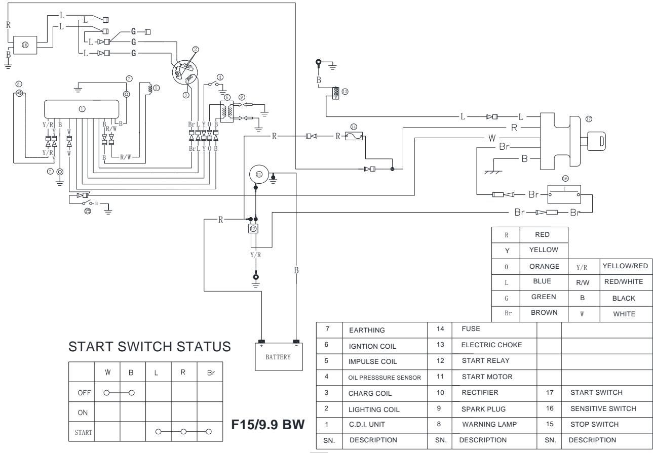
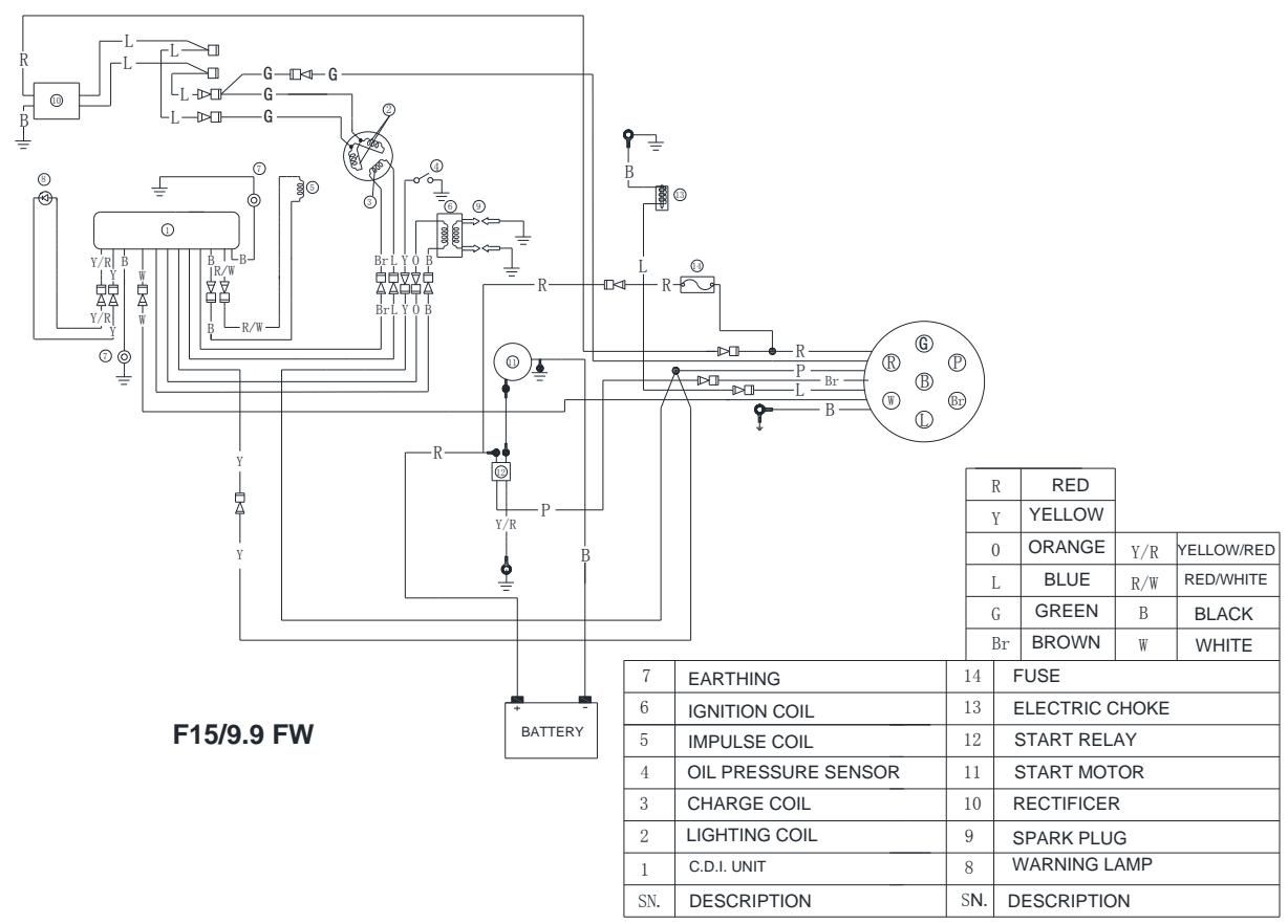
Circuit diagram
F15/9.9BM
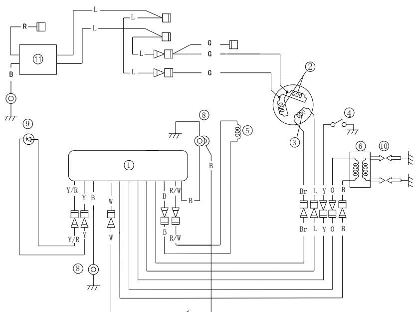
| 1 | C.D.I. | R: | red |
|---|---|---|---|
| 2 | LIGHTING COIL | Y: | yellow |
| 3 | CHARGE COIL | O: | orange |
| 4 | OIL PRESSURE SWITCH | L: | blue |
| 5 | IMPULSE COIL | G: | green |
| 6 | IGNITION COIL | B: | black |
| 7 | STOP SWITCH | W: | white |
| 8 | EARTHING | Br: | brown |
| 9 | WARNING LAMP | Y/R: | yellow/red |
| 10 | SPARK PLUG | R/W: | red/white |
F15/9.9BM
F15/9.9BW
F15/9.9FW
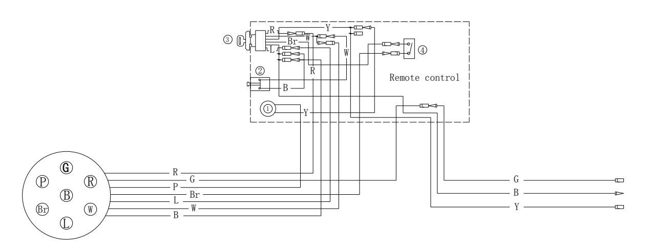
| R | red | 4 | Switch | ||
|---|---|---|---|---|---|
| Y | yellow | Y/R | yellow/red | 3 | Ignition |
| L | blue | R/W | red/white | 2 | Engine stop switch |
| G | green | В | black | 1 | Buzzer |
| Br | brown | W | white | SN. | DESCRIPTION |