Parsun F2.6 Outboard Engine Service Manual
Table of Contents
- General Information
- Explosive Drawing and Symbol
- Specifications
- Periodic Service
- Recoil Starter
- Ignition System
- Fuel System (Detailed)
- Power Unit (Detailed)
- Upper Unit
- Lower Unit
- Common Troubles and Solutions
WARNING:
General Information
Identification
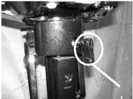
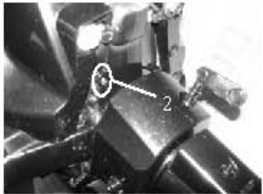
The outboard motor serial number is marked on the label.The label can be found on the bracket left assembly or on the upper part ofthe bracket swivel.Record your outboard motor serial number inthe spacesprovided to assistyou in orderingspare parts from yourParsundealer.To prevent from theft,theserialnumberlabel will be destroyedif removed from theoutboard motor.

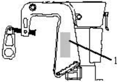
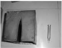
- 1.Outboardmotorserialnumberlocation Serial number as follows:
PRODUCTION CODE
Propeller Selection
The performance of your outboard motor will be critically affected by your choice of propeller, as an incorrect choice could adversely affect performance.
For a greater boat load and a low engine speed, a smaller-pitch propeller is more suitable. correct engine speed to be maintained.
When the engine is running at full throttle position, the suitable propeller should be used according performance.
| Propeller sizes | Material |
|---|---|
| 71/4×6 | Aluminum alloy |
| 71/4×51/2 | Aluminum alloy |
| 71/4×71/4 | Aluminum alloy |
| 71/4×81/4 | Aluminum alloy |
| 71/2×51/2 | Aluminum alloy |
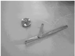
Emergency Start
If the starting device is not working, the engine can be started by emergency start cable.
- 中
- When you start the engine by emergency start cable, please ensure the shift rod is in NEUTRAL position.
- items far away.Don't touch flywheel or other moving parts.
- When starting and operating, don't touch ignition coil, spark plug cap or other electric parts.
The procedure is as follows:
- 1.Remove the top cowling.
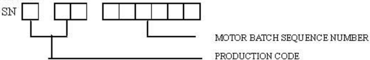
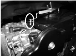
- Remove the bolts fixing the fuel tank.
- 3.Lift thefuel tankand remove threebolts.
- 4.Lift the starter and remove choke cablefrom carburetor
- 5.Remove the starter.
- Install the bolts to fix the flywheel cover
- 7.Install theboltstofixthefueltank.
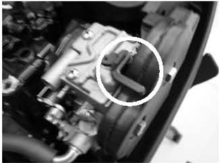
- 8.When the engine is cold , circumvolve the lever of carburetor in order to operate choke system. Return lever to home position after engine starts.
- 9.Insert the knot of the cable in the notch of flywheel rotor, and wind the cable around flywheel several rounds in clockwise direction.
- Pull the manual starter handle slowly until you feel resistance.
- Give a strong pull to start the engine.Repeat if necessary.


Safety While Working
To prevent the danger or accidents when performing maintenance and repair, and improve the work efficiency, please obey the following safety procedures.
1. Fire Prevention
Gasoline (petrol), lubricant and grease are highly flammable. While working, keep away from heat, sparks and open flames.
2. Ventilation
and deadly if inhaled in large quantities. When test-running an engine indoors, maintain good ventilation.
3. Self-Protection
Protect your eyes with suitable safety glasses or safety goggles, when drilling, grinding or operating air compressor. Protect hands and feet by wearing protective work clothes, safety gloves and shoes if necessary.
4. Lubricants and Sealing Fluids
When performing maintenance procedures and repair to Parsun outboards, use only products provided or recommended by our Company.
Under normal conditions of use, there should be no hazards from the use of the lubricants mentioned in this manual, but safety is all-important, and by adopting good safety practices, any risk is minimized.
A summary of the most important precautions is as follows:
- ① To protect the skin, the application of a suitable barrier cream to the hands before working is recommended.
- ? Clothingwhich has become contaminatedwithlubricantsshould be changed as soon as practicable, and washed before further use.
- ③Avoid skin contact with lubricants.
- @ Hands and any other part of the body which have been in contact with lubricants or lubricant-contaminated clothing, should be thoroughly washed with hot water and soap as soon as practicable.
- A supply of clean lint-free cloths should be available for wiping run-off lubricants or grease.
5. Good Working Practices
- ① Follow the tightening torque instruction. When tightening bolts, nuts and screws, tighten the large sizes first, and tighten inner-positioned fixings before outer-positioned ones.
- Q Use the recommended special tools to protect parts from damage.Use the right tool in the right manner.
Disassembly and Assembly
When disassembly and assembly, please follow the following principles:
- Use special tools when disassembling and assembling.
- 2.Clean dirt before disassembling the parts.
- 3.Oil the contact surfaces of moving parts before assembly.
- 4.Install bearing with the manufacturer's markings on the side exposed to view and liberally oil the bearing.
- When installing oil seals, apply a light coating of water-resistant grease to the ledge and outside diameter.
- 6.After assembly, check if the moving parts operate normally.
One-Time Use Parts
One-time use parts are gasket, oil seal, O-ring, cotter pin and spring, ring, and etc.. When re-assembling outboard engine, you must change the one-time use parts.
Pre-Delivery Check
To ensure the using, please inspect the following before delivery.
1. Checking Fuel System
Check if the fuel pipe is connected firmly, and if the fuel tank is filled with fuel.
CAUTION:
Do not usepre-mixed fuel for this 4-stoke outboard engine.
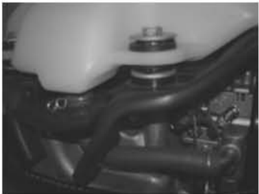
2. Checking Oil Level
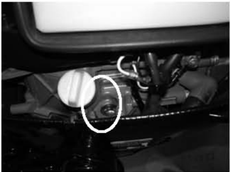
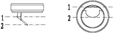
Check the Engine Oil Level
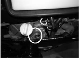
Check engine oil level from oil level checking hole.
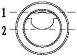
- High position mark 2. Low position mark
Ensure the oil level between the marks of upper and lower.If above upper level, drain engine oil; if below lower mark, add engine oil up to upper level.
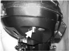
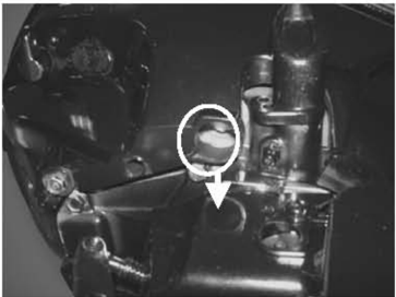
Check the Gear Oil Level
Remove the oil level plug. Check if the gear oil overflows at the oil level checking hole. If so, install the oil level plug and tighten it according to specified torque.
Otherwise please add gear oil.
- Oil level plug
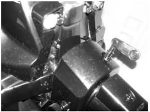
3. Check Steering System
Check if steering is stable.
Check if steering fiction is adjusted correctly. Turn clamp handle screw clockwise to increase resistance.
Turn clamp handle screw counter clockwise to lower resistance.
4. Check Shift Lever and Throttle
Check if the shift lever is operated smoothly.
Check if the throttle grip is turned smoothly from full closed position to full open position.
5. Check Engine Stop Switch Assembly
Check if the engine stops when pushing the engine stop switch assembly or pulling out the stopper hang rope.
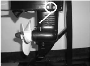
6. Check Cooling Water Checking Hole
When the engine is running, check if
- Clamp handle screw
coolingwater overflows at the coolingwater checkinghole.
7. Breaking-In Running
- Initial 1 hour: operate the engine at 2000 r/min or about a half throttle.
- ② The second hour: operate the engine at 3000 r/min or about 3/4 throttle.
- ? The following 8 hours: operate the engine at full throttle continuously. Each operation time doesn't exceed 5 minutes.
8. Inspection After Breaking-In Running
- ① Check if gear oil contains water.
- ② Check if the fuel line leaks.
- ? After breaking-in running, operate the engine at idling speed. Use cleaning tool to wash over the cooling water passage by fresh water.
- 9.After breaking-in running, inspect idling speed.
- ② Using the tachometer to measure idling speed RPM. If out of specification, adjust it. Idling speed: 1800~2000 r/min
- ① Preheating engine for 5 minutes.
- ? Turn the throttle stop screw clockwise or counter clockwise1.throttle stop screw until the specified idling speed is attained.
- ④ After adjusting idling speed, picking up RPM several times to check the engine's stability.

Special Tools and Detection Device
When performing maintenance and repair, you need to use all kinds of special tools and detection device.The use of correct tools will improve the work efficiency and avoid of the damage to the people and outboard engines.
Special Tools
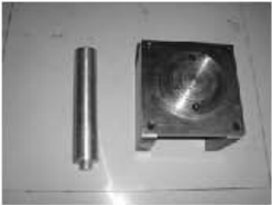
Piston slider
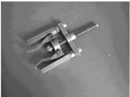
Flywheel holder and puller
- Cooling water checking hole
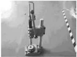
Bearing puller
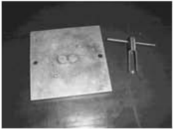
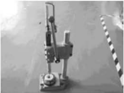
Valve spring compressor
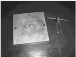
Oil seal installer tool
Housing bearing installer
Lower casing cover bearing installer
Housingoil seal installer
Sleeve bearingwith guard board installer tool
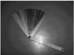
Space gage
Lower casingbracket and sleeve bearing without guard board installer tool
Lower casing bracket drive shaft oil seal installer tool
Detection Device
Digital tachometer
Digital universal meter

Peak voltage adaptor

Explosive Drawing and Symbol
Explosive Drawing
| 多国号网 | 零作号 零件名称 PART NO. DESORIPTION | 数量 QTY | 鲁性 RERARKS | |
|---|---|---|---|---|
| GB/TS743-2000 六角根检M6z40 | HLT | |||
| F2.6-03000016 聚光圆定板 | nm K PP 300 | |||
| F←-03000021 系光橡改管 | 1 | |||
| 490F40419-953 水系内光0形围 | 0- | 1 | ||
| F2.6-03000015 水泵内光 | URL 3OKO | 1 | ||
| F2.6-03000100 叶轮组件 | JIPEAEL IST | 1 | ||
| F2.6-03000010 外板 | OITATS | 1 | ||
| F2.6-03000009 0形封围 | 1 | |||
| F4-03000013 定位销小红18 | PIR | |||
| 10 | F2.6-03000007水聚座害封垫 | Riger, Fim PAP | 1 | |
| 10F2.6~0300000水聚座 | WNSI, KRTHL E | 1 |
- 1 Parts explosive drawing
- Screwspecification and specified torque
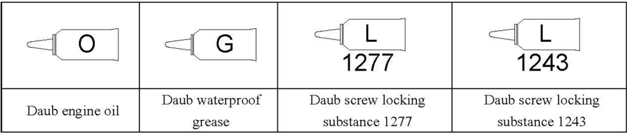
- Oil, fluid sealant or locking substance daubing point
- Spare parts details
Symbol
Specifications
Outboard Engine Specifications
| Item | Item | Description | Item | Item | Description |
|---|---|---|---|---|---|
| Dimension | Overall length | 645mm | n! Power | Spark plug | BPR7HS |
| Dimension | Overall width | 343mm | n! Power | Exhaust system | Under water |
| Dimension | Overall height | 1013mm | n! Power | Lubrication system | Splash lubrication |
| Weight | Weight | 18.0kg | pue Fuel: | Fuel type | Unleaded regular gasoline |
| Performance | Max output | 1.9Kw(2.6hp)@5500r/min | pue Fuel: | Fuel standard | PON86、RON91 |
| Performance | Full throttle operation | 5250~5750r/min | pue Fuel: | Fuel tank capacity | 1.2L |
| Performance | Max fuel consumption | 1.1L/h@5500r/min | pue Fuel: | Recommended engine oil | APISE、SF、SE-SF、 SG-CD SAE 10W30、10W40 |
| Performance | Idle speed (Neutral) | 1900±100r/min | pue Fuel: | Engine oil quantity | 0.35L |
| Unit Powerl | Type | 4 stroke,OHV | pue Fuel: | Recommended gear oil | Hypoid gear oil SAE #90 |
| Unit Powerl | Number of cylinders | 1 | pue Fuel: | Gearoil quantity | 75mm3 |
| Unit Powerl | Displacement | 72cm3 | Bracket | Tilt angle | 0°4°,8°,12° |
| Unit Powerl | BorexStroke | 54.0mmX31.5mm | Bracket | Tilt-up angle | 80° |
| Unit Powerl | Compression ratio | 9.0 | Bracket | Steering angle | 360° |
| Unit Powerl | Number of carburetor | 1 | Bracket | Gear positions | F-N |
| Unit Powerl | Control system | Tiller control | Unit Drive | Gear ratio | 2.08(27/13) |
| Unit Powerl | Starting system | Recoil starter | Unit Drive | Gear type | Bevel gear |
| Unit Powerl | Ignition control system | T.C.I | Unit Drive | Propeller direction | Clockwise |
| Unit Powerl | Starting enrichment | Chock valve | Unit Drive | Propeller drive system | Spline |
Maintenance Information
Power Unit
| Item | Item | Description | Item | Item | Item | Description |
|---|---|---|---|---|---|---|
| 0.1mm | Valve | Valve clearance (cold) | Intake | 0.08~0.12mm | ||
| Warp limit | 0.1mm | Valve | Valve clearance (cold) | Exhaust | 0.08~0.12mm | |
| Bore | 54.00~54.015mm | Face width | Intake | 1.84~2.26mm | ||
| Wear limit | 54.1mm | Face width | Exhaust | 1.84~2.26mm | ||
| Taper limit | 0.08mm | Seat width | Intake | 0.6~0.8mm | ||
| Out of round limit | 0.05mm | Seat width | Exhaust | 0.6~0.8mm | ||
| Piston diameter | 58.950~58.965mm | Margin thickness | Intake | 0.7mm | ||
| Measuring point height | Omm (from the Bottom of piston) | Margin thickness | Exhaust | 1.0mm | ||
| Piston-to-cylinder clearance | 0.035~0.065mm | Head diameter | Intake | 23.9~24.1mm | ||
| Pin boss inside diameter | 12.009~12.017mm | Head diameter | Exhaust | 21.9~22.1mm | ||
| Piston pin outside diameter | Piston pin outside diameter | 11.995~12.000mm | Stem outside diameter | Intake | 5.475~5.490mm | |
| 0.97~0.99mm | Stem outside diameter | Exhaust | 5.460~5.475mm | |||
| Thickness Breadth | 1.95~2.15mm | Guide inside diameter Stemto | Intake | 5.500~5.512mm | ||
| End gap | 0.15~0.30mm | Guide inside diameter Stemto | Exhaust | |||
| Wear limit | 0.40mm | guide clearance | Intake | 0.010~0.037mm | ||
| Side clearance | Side clearance | guide clearance | Exhaust | 0.025~0.052mm | ||
| 0.04~0.08mm | Rod runout limit | Rod runout limit | 0.03mm | |||
| Thickness | 1.17~1.19mm | Pushrodrunoutlimit | Pushrodrunoutlimit | Pushrodrunoutlimit | 0.5mm | |
| Breadth | 2.30~2.50mm | alve spring | Free length | Free length | 35.0mm | |
| End gap | 0.30~0.45mm | alve spring | Free length limit | Free length limit | 34.0mm | |
| Wear limit | 0.60mm | alve spring | Tiltlimit | Tiltlimit | 1.2mm | |
| Side clearance | 0.02~0.06mm | Connecting po. | Small end inside diameter. | Small end inside diameter. | 12.006~12.02mm | |
| Thickness | 1.87~1.95mm | Crankshaft | Big end oil clearance | Big end oil clearance | 0.016~0.046mm | |
| Breadth | 2.10~2.40mm | Crankpin width | Crankpin width | 21.0~21.1mm | ||
| End gap | 0.20~0.70mm | Crankpin diameter | Crankpin diameter | 23.969~23.984m m | ||
| Wear limit | 0.90mm | Crankshaft journal diameter | Crankshaft journal diameter | 21.980~21.993m m | ||
| Side clearance | 0.06~0.16mm | Round limit | Round limit | 0.01mm | ||
| Camshaft | Intake/Exhaust height | 26.139~26.239mm | Thermostat | Valve opening temperature | 58~62℃ | |
| Camshaft | Intake/Exhaust height | 26.139~26.239mm | Thermostat | Full-open temperature | 70°℃ | |
| Camshaft | Round diameter | 21.950~22.050mm | Thermostat | Valve lift | 3mm | |
| Camshaft | Journal diameter | 14.966~14.984mm | Thermostat | Valve lift | 3mm | |
| Camshaft | Camshaftroundlimit | 0.03mm | Thermostat | Valve lift | 3mm |
Ignition System
| Item | Description | Item | Item | Description |
|---|---|---|---|---|
| Ignition timing | BTDC30° | Spark plug gap | Spark plug gap | 0.6~0.7mm |
| T.C.I system output peakvoltage | 130V | Ignitor ass'y resistance | Primary coil | 1.6~1.9Ω |
| T.C.I air gap | 0.4~0.6mm | Ignitor ass'y resistance | Secondary coil | 5.8~7.0K Ω |
Tightening Torque
| Parttobe tightened | Parttobe tightened | Parttobe tightened | Part name | Thread size | Quantity | Torque |
|---|---|---|---|---|---|---|
| Oil drain | Oil drain | Bolt | M8 | 1 | 18Nm | |
| Spark plug | Spark plug | 一 | M14 | 1 | 25 Nm | |
| Recoil starter | Recoil starter | Bolt | M6 | 3 | 8 Nm | |
| Flywheel rotor ass'y | Flywheel rotor ass'y | Nut | M10 | 1 | 44 Nm | |
| Carburetor | Carburetor | Bolt | M6 | 2 | 8Nm | |
| Exhaust tester | Exhaust tester | Bolt | M8 | 1 | 20 Nm | |
| Cylinder head | 1st tightening | Bolt | M8 | 4 | 14 Nm | |
| 2nd tightening | Bolt | M8 | 4 | 30 Nm | ||
| Cylinder | lst tightening | Bolt | M6 | 6 | 5 Nm | |
| head cover | 2nd tightening | Bolt | M6 | 6 | 12 Nm | |
| Rocker arm screw bolt | Rocker arm screw bolt | Bolt | M6 | 2 | 10 Nm | |
| Locknut (rocker arm) | Locknut (rocker arm) | Nut | M6x0.75 | 2 | 10 Nm | |
| Oil seal housing | Oil seal housing | Bolt | M8 | 1 | 18Nm | |
| Power unit mounting | Power unit mounting | Bolt | M6 | 6 | 11Nm | |
| Thermostat cover | Thermostat cover | Bolt | M6 | 3 | 8 Nm | |
| Crankcase | 1st tightening | Bolt | M6 | 8 | 5 Nm | |
| 2nd tightening | Bolt | M6 | 8 | 11 Nm | ||
| Connecting po1 | 1st tightening | Bolt | M7 | 2 | 5Nm | |
| 2nd tightening | Bolt | M7 | 2 | 9 Nm | ||
| Oil splash gear unit | Oil splash gear unit | Bolt | M6 | 1 | 13 Nm | |
| Lower unit | 1st tightening | Bolt | M6 | 3 | 3 Nm | |
| mounting | 2nd tightening | Bolt | M6 | 3 | 8Nm | |
| Lower unit housing cover | 1st tightening | Bolt | M6 | 2 | 6Nm | |
| Lower unit housing cover | 2nd tightening | Bolt | M6 | 2 | 11 Nm | |
| Anode | 1st tightening | Bolt | M6 | 1 | 3Nm | |
| Anode | 2nd tightening | Bolt | M6 | 1 | 8Nm | |
| Water pump housing | 1st tightening | Bolt | M6 | 4 | 3Nm | |
| Water pump housing | 2nd tightening | Bolt | M6 | 4 | 8Nm | |
| Water pump base | 1st tightening | Bolt | M6 | 1 | 3 Nm | |
| Water pump base | 2nd tightening | Bolt | M6 | 1 | 8Nm | |
| Steering handle mounting | Steering handle mounting | Bolt | M8 | 1 | 26 Nm | |
| Shiftleverbracket | Shiftleverbracket | Bolt | M6 | 1 | 5Nm | |
| Swivel bracket | Swivel bracket | Nut | M6 | 4 | 12 Nm | |
| Clamp bracket | Clamp bracket | Nut | M8 | 1 | 16 Nm |
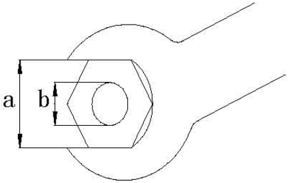
General Torque
| Nut (a) | Bolt (b) | Torque |
|---|---|---|
| 8mm | M5 | 5Nm |
| 10mm | M6 | 8 Nm |
| 12mm | M8 | 18 Nm |
| 14mm | M10 | 36 Nm |
| 17mm | M12 | 43 Nm |
Periodic Service
Maintenance Timetable
| Items | Contents | Initial maintenace | Initial maintenace | General maintenance period | General maintenance period |
|---|---|---|---|---|---|
| Items | Contents | 10hours (1month) | 50hours (3months) | 100 hours (6months) | 200 hours (1 year) |
| Anode | Inspection/replacement | 0 | |||
| Spark plug | Cleaning/adjustment /replacement | O | |||
| Grease points | Greasing | O | |||
| Bolts and nuts | Inspection | O | O | ||
| Fuel tank and fuel line | Inspection | ||||
| Fuel filter | Inspection/replacement | O | |||
| Carburetor | Inspection/replacement | O | |||
| Outboard outside | Inspection/replacement | O | |||
| Idling speed | Inspection/adjustment | O | |||
| Engine oil | Replacement | O | |||
| Valve cleanrance | Inspection/ adjustment | O | |||
| Ignition timing | Inspection | O | |||
| T.C.I air gap | Inspection/ adjustment | O | |||
| Thermostat | Inspection | O | |||
| Cooling water passage | Inspection/Cleaning | O | |||
| Gear oil | Replacement | 0 | |||
| Propeller | Inspection/replacement |
CAUTION:
After running the outboard engine in saltwater,waste water or mud water,wash over the engine byfreshwaterimmediately.
If using leaded gasoline frequently, check the valve and components each 100 hours.
Fuel System
- CHECKFUELTANK,CARBURETOR,FUEL
Check if fuel tank, carburetor, fuel pump and fuel pipe are damaged or leaked. Replace if necessary. Check if the fuel filter on the tank is dirty. Clean dirt or replace it if necessary.
2. Check Fuel Cock
Check if fuel cock is cracked, damaged or leaking. Replace if necessary.
Power Unit
Engine Oil Level
- From oillevel checking hole,check if engine oillevelisbetween thefollowingmarks of the upper and lower.
- Oil level plug 2.Oilrule
- 3.Highpositionmark4.Lowpositionmark
- If above the upper mark, drain the engine oil; if below lower mark, add engine oil up to upper mark.
CAUTION:
Run the engine for a few minutes and then turn it off,wait for several minutes, and check the engine oil level bytheoil checkingholeagain.
If the engine oil still not within the proper level, add/drain as needed.
Changing Engine Oil
- Remove oil level plug, drain plug with washer and gasket; drain off the engine oil.
- Install new gasket and washer; install drain plug.

- Fill engine oil into the crankcase through oil filler hole.
Engine oil quantity: 0.35L
Oil type: API SE, SF, SE-SF, SG-CD SAE 10W30, 10W40
- Install oil level plug.
- 5.Check engine oil level.
CAUTION:
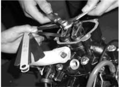
Rotate the flywheel clockwise so that rocker arm is in free position, before adjusting valve clearance (Dead point position on compression stroke).
- Remove stopper hang rope from engine stop switch assy. Remove spark plug cap from spark plug.
- 2.Remove cylinder head cover.
- Use feeler gauge to measure the clearance between rocker arm and valve rod top: if out of specification, adjust.
Valve clearance (cold position):0.08~0.12mm
- Remove spark plug cap and spark plug.
Spark Plug
- 2.Clean off carbon build-up on the electrodes.
- Check if the electrodes are corroded or have deposit, or if the washer is damaged. If necessary, change the spark plug.
- Inspect if the spark plug gap is within specification. If necessary, change the spark plug.
- Install spark plug. Use spark plug spanner to tighten it according to specified torque.
Spark plug type: BPR7HS

Specified torque: 25 Nm
Valve Clearance
Control System
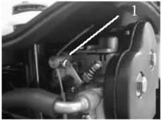
Throttle Grip
- Turn the throttle grip to fully closed position.
- Check if the throttle cable is slack and if the throttle lever touches the throttle stop screw.
- Loosen throttle cable stopper screw, adjust throttle cable position, and tighten throttle cable stop screw.
1.throttle cable stop screw
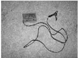
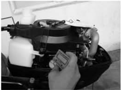
Idling Speed
Check idling speed, and adjust it if necessary.
- 1.Preheat engine for 5 minutes.
- Attach the tachometer to the spark plug wire to measure idling speed RPM. If out of specification, adjust it.
- Turn the throttle stop screw clockwise or counter clockwise, until the specified idlling speed is attained.
Idling speed: 1800~2000 r/min
NOTE:
Turning clockwise to increase idling speed.
Turning counter clockwise to decrea se idling speed.
CAUTION:
Before adjusting the idling speed, the throttle cable slack should be properly adjusted. After adjusting the idling speed, if necessary you can adjust the throttle cable again.
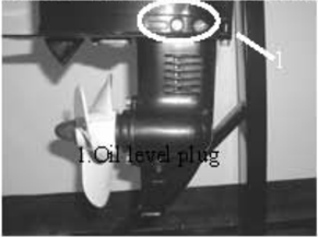
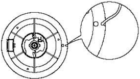
Check Gear Oil Level
Remove the oil level plugIf the gear oil overflows at the oil 1evel checking hole, the oil volume added is correct,otherwise please add gear oil.
- Oil level plug
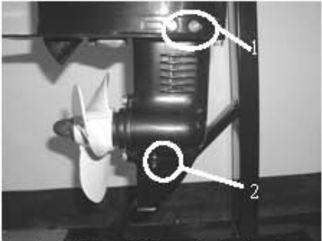
Changing Gear Oil
- 1.Hold the outboard engine in an upright position.
- 2.Place a container under the drain plug
- 3.Remove the drain plug,the oil level plug, and then drain the gear oil.
- 4.Add gear oil through the drain plug using pressure filling device.
- When gear oil overflows at the oil level checking hole, install the oil lev el plug 5.
- 6.Install the drain plug,then clean overflowing gear oil.
1.Oil level plug2.Drain plug
NOTE:
Check the drained gear oil.
If the gear oil is milky, please check the oil seal. If necessary, rep lace the oil seal.
CAUTION:
Must change drain plug washer each time.
Lower unit leakage check
Lower Unit Casing
Gear Oil
Connecting the leakage tester to the oil level checking hole to check the lower unit leakage.If the
General Inspection
Anode
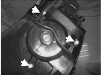
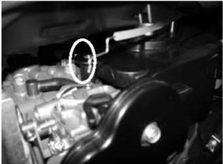
Inspect lower unit anode and engine anode (on the thermostat cover). Clean the greasy dirt and scales.If wear or damage is above 1/2, replace the anode.
CAUTION:
Cannot grease or paint the anode, or it will not operate properly.
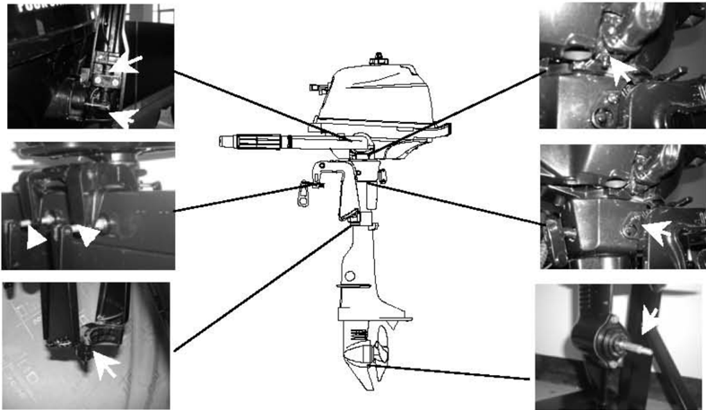
Grease Points
- Refer the illustration for greasing points, paint the water resistant grease.
- 2.Paint anti-corrosion grease on the propeller shaft.
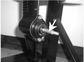
Cooling Water Passage
- 1.Inspect cooling water passage Ifblocked,clean it.
Cooling water passage inlet
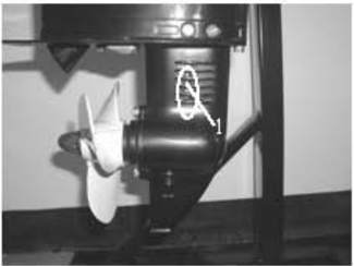
- 2.Place the outboard engine in the water and ensure the water level is above the anti-vortex plate, then start the engine.
- 3.Check if water overflows at the cooling water checking hole.If there is noflow or intermittent flow,check thecooling water passage.
1.Cooling water inlet
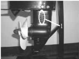
- Cooling water checking hole
Recoil Starter
NOTICE:
When you service, please wear safety glasses and gloves.Please rermove spark plug cap and stopper hang rope from stop switch assy, in case of the accidental start of the engine.
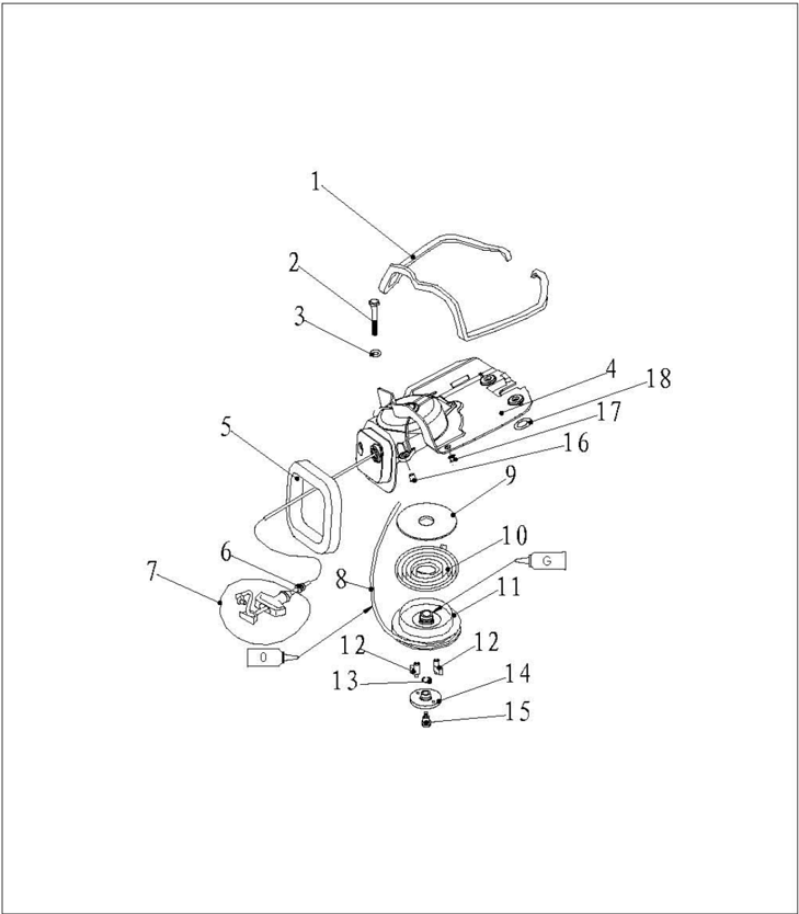
Explosive Drawing
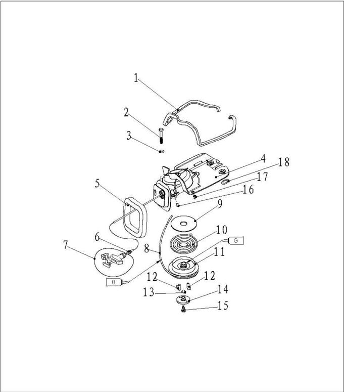
| 参照号码 SN. | 零件编号 PART NO. | 零件名称 DESCRIPTION | 数量 QTY | 备注 REMARKS | |
|---|---|---|---|---|---|
| 1 | F2.6-04070002 | 发泡密封条 | SEAL,FORTHY RUBBER | 1 | |
| 2 | CB/T5782-2000 | 六角螺栓M6x60 | BOLT | 3 | |
| 3 | CB/T97.1-85 | 平垫圈6 | WASHER | 3 | |
| 4 | F2.6-04070100 | 起动器外壳 | CASE,STARTER | 1 | |
| 5 | F2.6-04070001 | 发泡密封圈 | SEAL,FORTHY RUBBER | 1 | |
| 6 | F2.6-04070008 | 手柄减震圈 | DAMPER,HANDLE | 1 | |
| 7 | F4-04130100 | 起动手柄组件 | STARTER HANDLE ASSY | 1 | |
| 8 | F2.6-04070007 | 锦纶编织线Φ3 | WIRE,STARTER | 1 | |
| 9 | F2.6-04070003 | 起动轮减磨片 | WASHER,THRUST | 1 | |
| 10 | F4-04130005 | 满形弹簧 | SPRINC,VOLUTE | 1 |
| 参照号码 SN. | 零件编号 PART NO. | 零件名称 DESCRIPTION | 零件名称 DESCRIPTION | 数量 QTY | 备注 REMARKS |
|---|---|---|---|---|---|
| 11 | F2.6-04070004 | 起动轮 | DRULL,SHEAVE | 1 | |
| 12 | F2.6-04070005 | 斗 | PAWL,DRIVE | 2 | |
| 13 | F4-04130007 | 起动压板夹簧 | BOLT,STARTER | 1 | |
| 14 | F2.6-04070006 | 起动压板 | PLATE,PRESS | 1 | |
| 15 | F4-04130008 | 起动压板螺钉 | SCREW,STARTER | 1 | |
| 16 | F2.6-04000024 | 起动器垫管A | BUSH,STARTER | 3 | |
| 17 | F2.6-04000034 | 油箱减震圈B | DAMPER,FUEL TANK | 2 | |
| 18 | F2.6-04000025 | 起动器垫管B | BUSH,STARTER | 2 |
- Open the top cowling
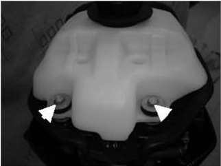
- 2.Remove bolts fixing the fuel tank.
- 3.Remove thefuel tankand takedown threebolts.
- 4.Lift the starter and remove choke cable from carburetor.
- 5.Removethestarter.
Disassembling
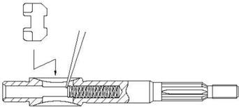
Starter Rope Replacement
- Pull the starter rope out, and insert it in the notch of the sheave drum. Turn the sheave drum clockwise until the volute spring is free.
- Pull the starter rope completely.
- Remove the starter handle cover from the starter handle, and remove the starter rope. Untie the knot at the end of the starter rope.
- Pull out the starter rope completely.
- Insert the new starter rope into the starter assembly, and fix the rope onto the sheave drum and starter. At the end of the rope tie a knot as shown.
- Insert the start rope in the notch of the sheave drum and turn the sheave drum several rounds in counterclockwisedirection.
- Pull the starter handle many times to check if the sheave drum rotates stably. If necessary, repeat step 6 and step 7.

Disassembling and Inspection
- Remove the start rope.
- Remove starter bolt, and remove press plate and drive pawl.
- 3.Remove the sheave drum
- WARNING Uninstall the sheave drum carefully, to ensure that the volute spring does not pop out to hurt
people.
- Remove the volute spring.
- Check if the drive pawl is cracked, worn or damaged. If necessary, replace it.
- Inspect if the drive spring is broken, cranked or damaged. If necessary, replace it.
- Check if the volute spring is broken, cranked or damaged. If necessary, replace it.

Reverse the steps of disassembling.
- 1.Put starter onto the power unit.
- 2.Screw the hexagon bolt, and tighten it according to the specified torque. Specified torque: 8Nm
Ignition System
NOTICE:
When checking and repairing the ignition system, keep your hand, clothes, hair or personal belongings away from the rotating flywheel.
Check ignition coil on insulated working table, to prevent electricity leak and electroshock.
Don't touch the ignition coil or spark plug when the engine is running, to avoid electroshock. Keep the wires away from the rotating flywheel, to prevent the wire from being cut, or the insulating layer of the wire from being worn.
When replacing fixing parts such as nuts and bolts, only parts from original manufacturer or parts made of same material and with strength can be used.Parts must be tightened according to the specified torques.
Explosive Drawing
Assembling
Installation

| 参照号码 SN. | 零件编号 PART NO. | 零件名称 DESCRIPTION | 数量 QTY | 备注 REMARKS |
|---|---|---|---|---|
| 1 | GB/T6171-86 | 六角螺母M10x1.25 | NUT 1 | |
| 2 | F4-04000021 | 飞轮垫圈 | WASHER 1 PULLEYSTARTER | |
| 3 | F2.6-04000016 | 起动轴套 | 1 | |
| F2.6-04000400 | 飞轮组件 | FLYWHELL ASSY 1 | ||
| F4-04000019 | 飞轮半圆键 | KEY 1 | ||
| 6 | GB/T5783-2000 | 六角螺栓M6x25 | BOLT 2 | |
| 7 | GB/T97.1-85 | 平垫圈6 | WASHBR 3 | |
| F2.6-04000600 | 高压包组件 | HIGH PRESSURE ASSY 1 | ||
| 9 | GB/T5783-2000 | 六角螺栓M6x12 | BOLT 1 |
Wiring Diagram
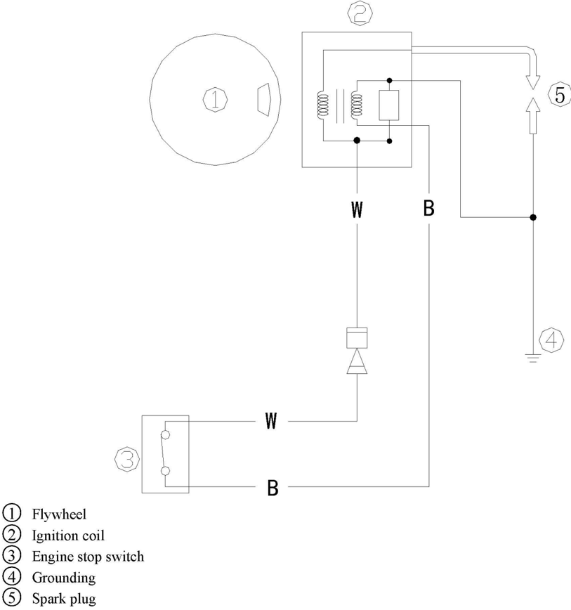
Wire beam color:W White
B Black
Spark Plug Ignition
- Remove spark plug cap from spark plug. .
- 2.Connect the ignition tester to the spark plug cap.
- 3.S Start the engine, and observe the sparks through the discharge window of the tester.
WARNING:
Do not touch any joint part of the leadwire of the tester.
Keep away from inflammable gas or liquid, to prevent accident resulting from spark ignition.
- Ignition coil peak voltage
- Remove spark plug cap.
- ② Disconnect ignition coil tip (W).
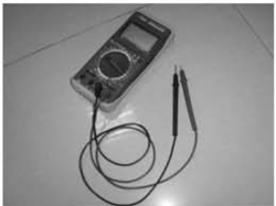
- ③ Measure the ignition coil peak voltage output by a digital universal meter and a peak voltage adapter. If below specification, check the ignition coil.
Peak voltage output: 130V (1500 r/min)
Digital universal meter
- Ignition coil resistance
- (1 Remove ignition coil and spark plug cap.
- Measure ignition coil resistance.If out of specification, replace it.
- Resistance: 1.6
1.9 Q(Tester (+) pole: white wire; Tester (-) pole: black wire) 5.87.0k Q (Tester (+) pole: white wire; Tester (-) pole: high-voltage wire)
Peak voltage adapter
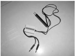
Spark Plug Cap
- 1.Remove the spark plug. Check if the spark plug cap is broken. Replace if necessary.
- Install the spark plug cap Turn it clockwise until it is tight.
Flywheel Maintenance
- 1.Use flywheel holder to remove the nut and starter pulley, use flywheel puller to remove flywheel.
- 2.Check if the flywheel is damaged or the permanent magnet part is firm. Replace if necessary.
Ignition Coil Inspection
Fuel System (Detailed)
NOTICE:
Gasoline is inflammable and highly volatile liquid.Its leakage can cause fire and explosion. Don't start the engine before all joints of the fuel system are connected or installed.When completing all maintenance steps, force short-time pressure to the fuel system to check for leakage.
Explosive Drawing
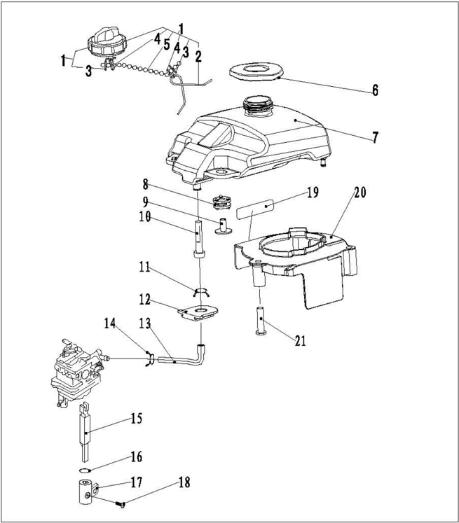
| 参照号码 SN. | 零件编号 PART NO. | 零件名称 DESCRIPTI0N | 数量 QTY | 备注 REMARKS | |
|---|---|---|---|---|---|
| 1 | F4-04120100 | 油箱盖组件 | TANK COVER ASSY | 1 | |
| 2 | F4-04120103 | 防脱落扭簧 | SPRING,PIEYENT DBSQUAMATING | 1 | |
| 3 | F4-04120105 | 防脱落卡片 | SERT MTAL PAREMT DESOAMUTING | 2 | |
| 4 | F4-04120106 | 钢丝锁圆 | BYBLRT,STEBL WIRB | 2 | |
| 5 | F4-04120104 | 防脱链 | CHAINPRETENT DESQUAMATING | 1 | |
| 6 | F2.6-04000033 | 油箱口减震围 | WASEER,DAMPER | 1 | |
| 7 | F2.6-04000026 | 油箱 | FUEL TANI,INNER | 1 | |
| 8 | F2.6-04000027 | 油箱减震围A | DAMPER ,FUBL TANK | 2 | |
| 9 | F2.6-04000028 | 油箱减震围垫管 | TURE ,DAMPER | 2 | |
| 10 | F4-04120005 | 油箱滤油芯 | FILTER,FUEL TAN | 1 |
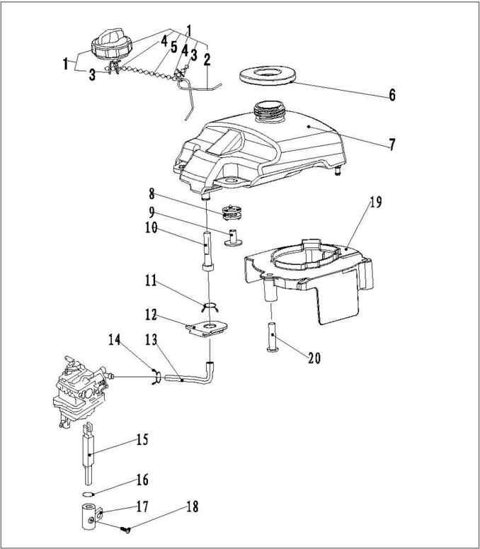
| 参照号码 8N. | 零件编号 PART NO. | 零件名称 DESCRIPTION | 数量 QTY | 备注 REMARKS |
|---|---|---|---|---|
| 11 | F4-05000010 | 油管夹赞 | SPRING,OIL TUBE 1 | |
| 12 | F4-04000032 | 油管减震块 | DAMPER,OIL TUBE 1 | |
| 13 | F2.6-04000029燃油管 | OILTUBE 1 | ||
| 14 | F2.6-04000030油管夹簧C | SPRING,OIL TUBE 1 | ||
| 15 | F2.6-04000017油开关连接杆 | CONNECTINGXODOILSWITCH 1 | ||
| 16 | JASOF40424-014油开关密封圈Φ13.8x2.40-RING | |||
| 17 | F2.6-00000004油开关旋钮 | KNOB,OIL SWITCH 1 | ||
| 18 | CB/T823-2000 | 十字槽小盘头蝶钉MSx8 | SCREW,PAN EBAD 1 | |
| 19 | F2.6-04000022飞轮导风罩 | VENTILATIYE COYER 1 | ||
| 20 | F2.6-04000023导风垫管 | TUBE,WASBER | 3 |
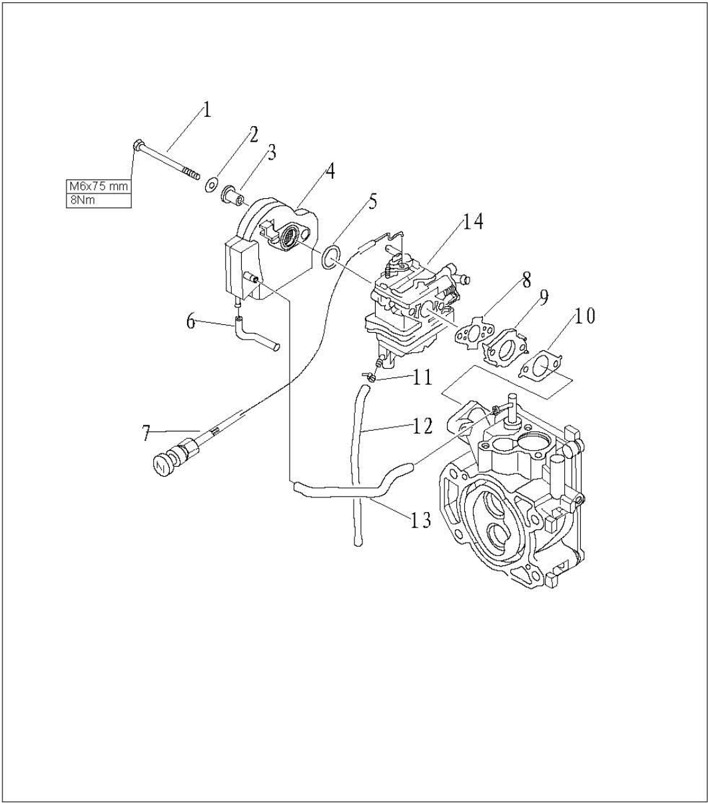
| SN. | 零件编号 PART NO. | 零件名称 DESCRIPTION | 数量 备注 QTY | REMARKS | |
|---|---|---|---|---|---|
| 1 | GB/T5782-2000 | 六角螺栓M6x75 | BOLT | 2 | |
| 2 | GB/T97.1-85 | 平垫圈6 | WASHER | 2 | |
| 3 | F2.6-04000012 | 进气消音器衬管 | BUSH,INTAKE SILENCB | 2 | |
| 4 | F2.6-04000300 | 进气消音器组件 | SILBNCE ASSY,INTAKB | 1 | |
| 5 | JAS0F40424-021 | 进气消音器0形圈 | O-RING | 1 | |
| 6 | F2.6-04000015 | 回气管BΦ2.5xΦ7x72 | HOSE | 1 | |
| 7 | F2.6-04070200 | 阻风门手柄组件 | CHOCK BANDLE ASSY | 1 | |
| 8 | F2.6-04000018 | 化油器密封垫B | GASKET,CARBURETOR AIRPROOF | 1 | |
| 9 | F2.6-04000011 | 化油器垫块 | INSULATOR,CARBURETOR | 1 | |
| 10 | F2.6-04000010 | 化油器密封垫A | GASKET,CARBURETOR AIRPROOF | 1 | |
| 11 | HT2.5x60 | 尼龙扎带60x2.5 | CLAMP | 1 | |
| 12 | F2.6-04000013 | 化油器放油管4xΦ7x140HOSE | 化油器放油管4xΦ7x140HOSE | 1 | |
| 13 | F2.6-04000014 | 回气管AΦ5xΦ9x130 | HSOB | 1 | |
| 14 | F2.6-04000200 | 化油器总成 | CARBURETOR | 1 |
Fuel Tank Removal and Inspection

- Open the top cowling.
- 2.Remove two bolts fixing the fuel tank.
- Pull the fuel tank out.
- Remove the fuel pipe from fuel tank.
- Inspect if the fuel tank and fuel tank cover for crack, leakage or damage. Replace if necessary.
- Inspect the tank strainer for dirt or clog. Clean or replace if necessary.
Intake System Removal and Inspection
- 1.Remove the bolt fixing air filter.
- 2.Remove air filter and carburetor.
- 3.Check if air filter is cracked or damaged.Replace it if necessary.
Power Unit (Detailed)
NOTICE:
To avoid accidental start of outboard engine during maintenance, please take enough safety measures assembly, and remove spark plug cap from spark plug.
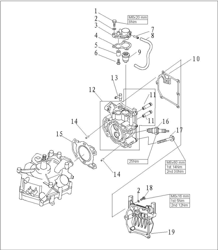
Explosive Drawing

| 参照号码 SN. | PART NO. | 零件名称 DESCRIPTION | 零件名称 DESCRIPTION | 数量 QTY | 备注 REMARKS |
|---|---|---|---|---|---|
| 1 | GB/T5783-2000 | 六角螺栓M6X20 | BOLT | 3 | |
| 2 | GB/T97.1-85 | 平垫图6 | VASHER,PLATE | 9 | |
| 3 | F2.6-04000501 | 节温器盖 | COFER,THBRMDSTAT | 1 | |
| 4 | F4-04000011 | 节温器盖密封垫 | GASKET,THERMOSTAT | 1 | |
| 5 | P4-04070003 | 节温器盖阳极 | BOONY | 1 | |
| 6 | GB/T818-85 | 十字槽盘头螺钉MSx25SCRBW,PABAD | 十字槽盘头螺钉MSx25SCRBW,PABAD | ||
| 7 | F4-04010002 | 气咀 | PIPB,IOINT | 1 | |
| 8 | F2.6-04000007 | 水管Φ5xΦ9x245 | PIPE,WATER | 1 | |
| 9 | T15-04000010 | 节温器 | THERMOSTAT | 1 | |
| 10 | F2.6-04000005 | 缸头罩密封垫 | GASKET,CYLINDER COVER | 1 | |
| 11 | 166F-010104 | 气门导管 | VALYE GOIDE BUSB | 2 | |
| 12 | F2.6-04040100 | 气缸头组件 | CYLINDER HEAD ASSY | 1 | |
| 13 | F15-04000005 | 水嘴组件(7/6)SPILEWATERASSY | 水嘴组件(7/6)SPILEWATERASSY | 1 | |
| 14 | P15-00000013 | 定位销4x12 | PIN | 2 |
| 参照号码 SN. | 零件编号 PARTNO. | 零件名称 DESCRIPTION | 数量 QTY | 备注 REMARKS | |
|---|---|---|---|---|---|
| 15 | F2.6-04000001 | 缸头复合垫 | GASKET,CYLINDER HEAD | 1 | |
| 16 | BPR7HS | 火花塞 | SPARK PLUG | 1 | |
| 17 | F4-04000034 | 气缸头螺栓B | BOLT | 4 | |
| 18 | GB/T5783-2000 | 六角螺栓M6x16 | BOLT | 6 | |
| 19 | F2.6-04000006 | 缸头罩 | COVER,CYLINDER HEAD | 1 |
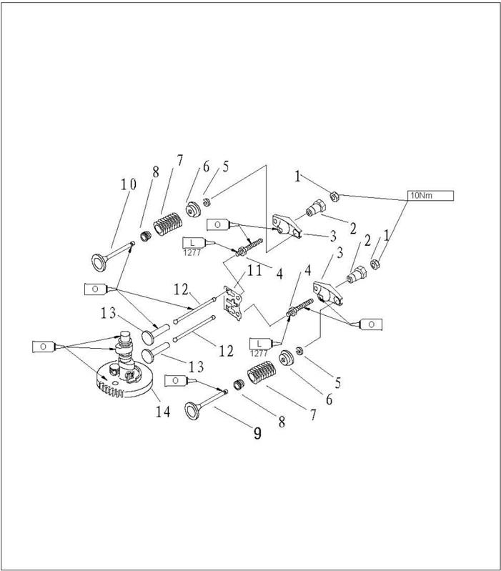
| 参照号码 SN. | 零件编号 PART NO. | 零件名称 DESCRIPTION | 零件名称 DESCRIPTION | 数量 QTY | 备注 REMARKS |
|---|---|---|---|---|---|
| 1 | 166F-010011 | 锁紧螺母 | LOCK NUT | 2 | |
| 2 | 166F-010010 | 摇臂球座 | PIVOT,ROCKER ARM | 2 | |
| 3 | 166F-010009 | 摇臂 | ARM,VALVE ROCKER | 2 | |
| 4 | 116F-010008 | 摇臂螺杆 | BOLT,ROCKER ARM | 2 | |
| 5 | 166F-010006 | 气门锁片 | CLAMP,VALVE | 2 | |
| 6 | F4-04080010 | 气门弹簧座 | SPRINC,VALVE RETAINER | 2 | |
| 7 | F4-04080008 | 气门弹簧 | SPRINC,VALVE STEM | 2 | |
| 8 | 166F-010003 | 进气门油封 | SEAL,VALVE STEM | 2 | |
| 9 | 166F-010001 | 进气门 | VALVE,INTAKE | 1 | |
| 10 | 166F-010002 | 排气门 | VALVE,EXHAUST | 1 | |
| 11 | F2.6-04040001 | 导向板 | PLATE,PUSH ROD | 1 | |
| 12 | F2.6-04000002 | 气门推杆 | ROD,VALVE PUSH | 2 | |
| 13 | 166F-000001 | 气门挺柱 | LIFTER,VALVE | 2 | |
| 14 | F2.6-04000100 | 凸轮减压组件 | CAMSHAFT ASSY | 1 |
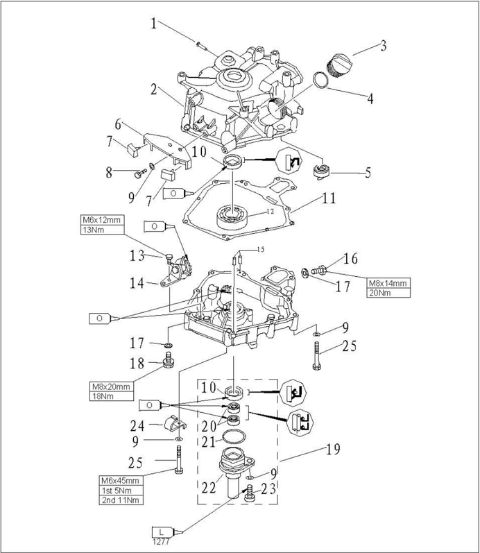
| 参照号码 SN. | 零件编号 PARTNO | 零件名称 DESCRIPTION | 数量 QTY | 备注 | REMARKS |
|---|---|---|---|---|---|
| 1 | T15-04010202 | 出水嘴 | PIPE,WATER 1 | ||
| 2 | F2.6-04010100 | 曲轴箱体 | CRANK CASE 1 | ||
| 3 | F15-07050004 | 加油口盖 | PLUG,0IL 1 | ||
| 4 | JAS0F40431-02加油口0型圈 | JAS0F40431-02加油口0型圈 | O-RING 1 | ||
| 5 | F2.6-04010102 | 油位器 | GAUGE,LEVEL 1 | ||
| 6 | F2.6-04000008 | 减震架 | BRACKET,DAMPER 1 | ||
| 7 | F2.6-04000009 | 橡胶减震块 | RUBBER BLOCK,DAMPER 2 | ||
| 8 | GB/T5783-2000 | 六角螺栓M6x20 | BOLT 2 | ||
| 9 | GB/T97.1-85 | 平垫圈6 | WASHER 11 | ||
| 10 | F2.6-04010001 | 曲轴油封SD20x30x7HS0ILSEAL | 2 | ||
| 11 | F2.6-04000004 | 曲轴箱体复合垫 | CRANK CASE COMPLEX GASKET 1 | ||
| 12 | 62/22C3 | 深沟球轴承 | BALL BEARING 1 | ||
| 13 | GB/T5783-2000 | 六角螺栓M6x12 | BOLT 1 | ||
| 14 | F2.6-04050100 | 甩油轮组件 | GEAR UINT ASSY 1 |

| 参照号码 SN. | 零件编号 PART NO. | 零件名称 DESCRIPTION | 备注 REMARKS | |
|---|---|---|---|---|
| 15 | F15-00000013 | 定位销4x12 | PIN | |
| 16 | GB/T5783-2000 | 六角螺栓M8x14 | BOLT | |
| 17 | F4-04000006 | 放油螺栓密封垫 | WASHER | |
| 18 | F4-04000001 | 放油螺栓M8x20 | BOLT ,DISCHARGING OIL | |
| 19 | F2.6-04060000 | 油封壳体组件 | OILSEAL SHELLASSY | |
| 20 | F2.6-04060002 | 驱动轴上油封K-56570ILSEAL | ||
| 21 | F4-04060002 | 油封壳体0型密封圈0RING | ||
| 22 | F2.6-04060001 | 油封壳体 | SHELL,OIL SEAL | |
| 23 | GB/T5783-2000 | 六角螺栓M8x20 | BOLT | |
| 24 | F25-05000013 | 线卡A | CLAMPA | |
| 25 | GB/T5782-2000 | 六角螺栓M6x45 | BOLT |
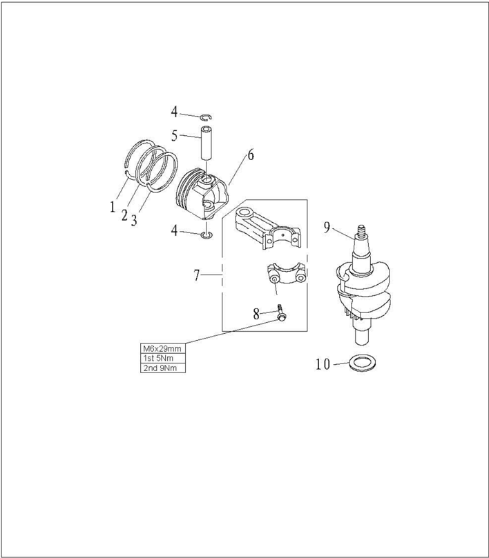
| 参照号码 SN. | 零件编号 PART NO. | 零件名称 DESCRIPTION | 数量 QTY | 备注 REMARKS | |
|---|---|---|---|---|---|
| 1 | F2.6-04020002 | 活塞气环1 | PISTON RING1 | 1 | |
| 2 | F2.6-04020003 | 活塞气环2 | PISTON RING2 | 1 | |
| 3 | F2.6-04020004 | 活塞组合油环 | COMBINED OIL RING | 1 | |
| 4 | F2.6-04020006 | 活塞销卡簧 | CIRCLIP | 2 | |
| 5 | F2.6-04020005 | 活塞销 | PIN,PISTON | 1 | |
| 6 | F2.6-04020001 | 活塞 | PISTON | 1 | |
| 7 | F2.6-04020100 | 连杆组件 | ROD,CONNECTING | 1 | |
| 8 | F2.6-04020103 | 连杆螺栓M6x30 | BOLT | 2 | |
| 9 | F2.6-04030000 | 曲轴组件 | CRANK ASSY | 1 | |
| 10 | F2.6-04000003 | 箱盖减磨片 | WASHER,PLATE | 1 |
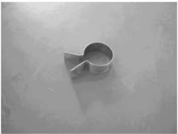
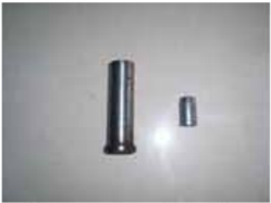
Piston slider
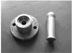
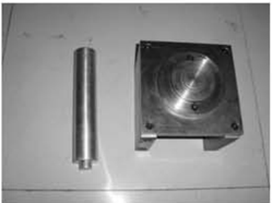
Housing bearing installer
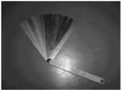
Space gauge
Disassembling Power Unit from Outboard Engine
- Open the top cowling.
- 2.Remove fuel tank;remove starter.
- Remove flywheel cover and throttle cable .
- 4.Remove air filter and carburetor.
- Remove bolts connecting power unit and upper casing.
- 6.Carry the power unit and put it onto the working table.
Disassembling and Inspection
Cylinder Cover
Disassembling
- 1.Remove the bolts of cylinder head cover.
- 2.Remove the bolts of the cylinder cover according to the reverse numbering sequence of the cylinder cover.
- 3.Remove the crankcase cover.Remove the valve push rod.
Special Tools
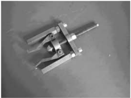
Bearing puller
Oil seal installer tool
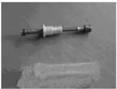
Valve spring compressor
Housing oil seal installer
- 4.Remove the rocker arm pivot,rocker arm,rocker arm shaft and pushrod plate.
Push Rod
Inspect valve push rod runout.Replace if exceeding the specified value. Valvepush rodrunout limit:0.5mm
Valve and Valve Pipe
- 1.Inspect the valve seat width. If not in the prescribed range,repair the valve seat Valve seat width:0.6~0.8mm
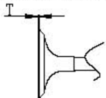
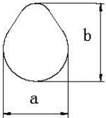
- Inspect the valve margin thickness (T). If not as in the prescribed value,replace the valve. The margin thickness of valve: T
- 3.Inspect the valve stem diameter.If not in the prescribed range,replace the valve. The diameter of valve stem:
- 4.Measure thevalve sterm runout.If exceeding the limit,replace the valve. Valve stem runout limit:0.03mm
- 5.Measure the inner diameter of the valve pipe.
Intake door.0.7mm
Exhiaust door:1.0omm
Intake:5.475~5.490mm
Exhaustvalve:5.460~5.475mm
Theinner diameter of the valvepipe:5.500~5.512m
CAUTION:
When replacing the valve,please use the new valve pipe andvalve oil seal.
Valve Spring
- 1.Measure the free length of valve spring.If less than prescribed value, replace.
- 2.Measure the valve spring tilt.If exceeding the prescribed limit, replace.
The minimum free 1ength: 34mm
The maximum tilt limit: 1.2mm
- Clean the carbon on the valve.
- Coat a thin layer of bluing dye evenly onto the seal face of thevalve seat.
- Lap the valve on valve seat by valve lapping tool.
- Measure thevalve seatwidth.
The valve face is with bluing dye.
If the valve and valve seat do not match, or the valve seat width does not conform to specified v alue,reface and lap the valve seat.
If the contact surface is not even,replace the valve pipe.
The valve seat width: 0.6~0.8mm
The maximumvalve seatwidth:1.1mm
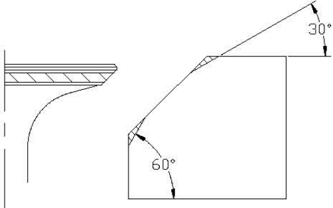
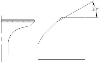
Valve Seat Cutting
- 1.Use 45°valve seat cutter to adjust the valve seat width.Turn the cutter clockwise until the valveseatface issmooth.
- 2.If thevalve seat is centered on thevalve face but it's toowide,to reduce thevalve seat width,use 30° cutter to adjust the top edge of the seat, and use 60° cutter to adjust the bottom edge of the seat.
- If the valve seat is too narrow and on the top edge of valve surface, use 30° cutter to adjust the top margin of the seat, and use 45° cutter to adjust the valve seat width if necessary.
Valve Rocker Arm
Check the rocker arm for crack, perforation or damage. Replace if necessary.
Valve Pipe Replacement
- 1.Knock out the valve pipe from the direction of combustion room.
- 2.Knock in the new valve pipe from the direction of the top of cylinder cover.
NOTE:
Coat the oil on the surface of pipe before installation.
- 3.Bore the inner diameter of pipe to the prescribed value by reamer.
Inner diameter of valve pipe: 5.500~5.512mm
NOTE:
When taking out the reamer, don't rotate it in counter clockwise direction.
Valve Seat Inspection
- 4.If the valve seal surface is too narrow and on the bottom edge of valve surface, use 60°cutter toadjust thebottom edgeof the seat,anduse45°cutter toadjust the valve seat width if necessary.
- Coat evenly a thin layer of lapping compound onto valve seat, and lap the valve by lapping tool.
- Clean up the remaining lapping compound
- 7.Inspect again the valve seat width.

CAUTION:
Do not overlap the valve. Turn the lapping tool evenly with a downward force of 40~50N. Do not contaminate push rod and valve pipe with lapping compound.
Thermostat
- Remove thermostat cover and thermostat.
- 2.S Suspend thermostat in the container with water.
- 3.Heat the container.
- 4.Inspect valve lift situation in the prescribedwater temperature.If out of specification,replace.
- 5.Install thermostat and thermostat cover.Tighten the bolts to specified torque.
| Watertemperature | The lift height |
|---|---|
| 58~62℃ | 0.05mmvalvelift |
| Over 70℃ | Over3mm |
Crankcase
Disassembling
- Remove the bolts according to the reverse numbering sequence of the crankcase cover .
- 2.Remove the crankcase cover.
- 3.Remove the camshaft and valve lifter.
- Remove the connecting rod bolt and connecting rod cap, and remove connecting rod and piston assembly.
- Use clipper to remove circlip, and remove piston pin and piston.
- 6.Remove crankcase and crankcase gasket.
- 7.Remove oil splasher gear assembly.
- 8.Remove oil seal shell bolts, and remove oil seal shell and oil seal.
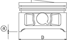
Piston
Measure piston outside diameter at the specified measuring point.If out of specification,replace.
Piston diameter:
53.950~53.965mm
Measuring point@: Omm
Cylinder Bore
- Measure cylinder bore separately at measuring point ①, , ③. At each point, measure the cylinder bore at places D1, D3, D5 parallel to the crankcase and at places D2, D4, D6 vertical to the crankshaft.
Measuring point height:
- ②40mm;
①100mm;
③70mm
Cylinder bore:
54.00~54.015mm
Limit size:
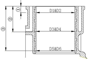
54.10mm
- Calculate taper limit and round limit.If out of specification,replace crankcase.
Taper limit: 0.08mm(D1-D5, D2-D6)
Round limit: 0.05mm(D2-D1, D6-D5)
Piston Pin Diameter
Measure piston pin outside diameter. If out of specification, replace the piston pin.
Piston pin outside diameter:11.996~12.000mm
Piston Ring
- Push the piston ring parallel with the piston into the specified measuring point of the cylinder (1omm from conjunction surface).
If out of specification,replace the piston ring.
Top ring 0.15~0.30mnm/0.4mm
- Measure end gap by space gauge. End gap (installed) / limit size:
2nd ring 0.30~0.45mm/0.6mm
Oil ring 0.2~0.7mm/0.9mm
- 3.Install piston ring to piston, and measure side clearance between piston ring and its slot by clearance gauge. If out of specification, replace the piston ring.
Side clearance:
Top ring 0.04~0.08mm
2nd ring 0.02~0.06mm
Oil ring 0.06~0.16mm
Camshaft Decompressor
- Inspect camshaft decompressor, gear, and weight. If gear is worn/damaged/cracked, replace. If weight is unsmoothly moving, replace.
- 2.Measure camshaft lobe diameter@ and height .If out of specification, replace it.
Camshaft: 26.136~26.239mm
@Camshaft:21.950~22.050mm
- Measure camshaft diameter. If out of specification, replace the camshaft.
Camshaft journal wear limit: 14.934mm
Crankshaft
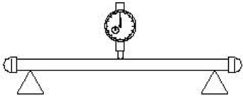
- 1.Measure crankshaft brace.If out of specification, replace.
- Measure crankshaft runout. If out of specification, replace.
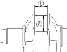
Crankshaft brace diameter @ : 23.969~23.984mm
Crankshaft brace width : 21.0~21.1mm
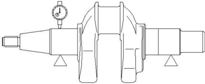
Crankshaft runout limit: 0.01mm
- Put a piece of plastic space gauge on to the crankpin in parallel to the crankshaft.
Oil Clearance
- 2.Assemble the connecting rod to the crankpin.
- 3.Tighten the connecting rod bolts to the specified torque.
Tightening torque:
Firsttime
- 5Nm
Second time
9Nm
- 4.Remove the connecting rod, measure the compressed width of the plastic space gauge. If out of specification, replace the connecting rod.
Oil clearance: 0. 016~0. 046mm
Note:
Don't rotate the connecting rod before completing measurement.
Valve Lifter
- Inspect valve lifter for wear or damage. Replace if necessary.
- 2.Measure valve lifter outside diameter.If out of specification, replace the valve lifter. Valvelifteroutsidediameter:7.9650mm
Oil Splash Gear

Inspect oil splash gear unit, if slow-moving/wear/damage/crack, replace.
Crankshaft Bearing
Inspect bearing, if pitting/rumbling, replace.
NOTE:
Don't remove bearing unless you replace it.
Oil Seal Housing
- Inspect O-ring for crack/damage. Replace if necessary.
- Inspect oil seal housing for crack/damage. Replace if necessary.
Crankcase and Crankcase Cover
- Inspect crankcase cover. If cracked/damaged, replace.
- 2.Inspect cooling water passage for dirt or clog. Clean if necessary.
Full Installation
Piston Connecting Rod Installation
Install piston, connecting rod, piston pin and piston pin circlip.
NOTE:
When installing,make sure that the mark on the connecting rod is at the same side of the mark on the piston crown.
Use new piston pin circlip. Make sure that circlip gap is not aligned with the circlip slot gap.
Piston Ring Installation
- Install oil ring, 2nd ring and top ring.
NOTE:
Make sure that the mark is toward the piston crown when installing the 2nd ring.
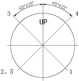
- Picture of the piston ring gap
Oil ring end gap 2 (expanded ring)
Oil ring end gap 1 (lower rail)
Oil ring end gap 3 (upper rail)
2nd piston ring end gap 4
Top piston ring end gap 5


Piston Installation
Use piston slider to install piston, and make sure the piston crown “Up” is toward the flywheel side.

NOTE:
Apply motor oil to the piston and piston ring side when installing.
Oil Seal Housing Installation
- Install oil seals 10.8x21x7 (2 pieces) by oil seal installer tool.
- Install oil seals B20 X 30 X 7 by oil seal installer tool.
NOTE:
- ① Apply grease onto new seal before installation.
- ② Make sure the oil seal spring direction as shown.
Crankshaft Installation
- Install the crankshaft bearing to crankcase by special tools (if change bearing). Install oil seal.
Housing bearing installer
NOTE:
Fit the bearing with its manufacturer's mark toward the direction of the flywheel side.Apply motor oil to the new oil seal installing.
- Install crankshaft to crankshaft case.
- Install connecting rod cover, and tighten the connecting rod bolt to the specified torque. Specified torque:12 Nm
NOTE:
- 1.Install valve lifter.
Apply motor oil to moving parts before installing.
Camshaft Installation
- Install camshaft. Make sure that the camshaft gear mark is aligned with the camshaft timing gear mark.
NOTE:
Housing oil seal installer
Oil seal installing direction
Apply motor oil to moving parts before installing.
- Install oil seal housing.
Crankcase Cover Installation
- Install oil splasher gear assembly.
- Install crankcase cover, and tighten the bolts twice as shown.
Tightening torque:
1st5Nm
2nd 11 Nm
NOTE:
Apply motor oil to moving parts before installing.
Upper Unit
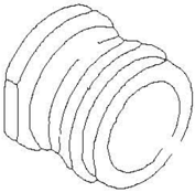
Top Cowling
Explosive drawing
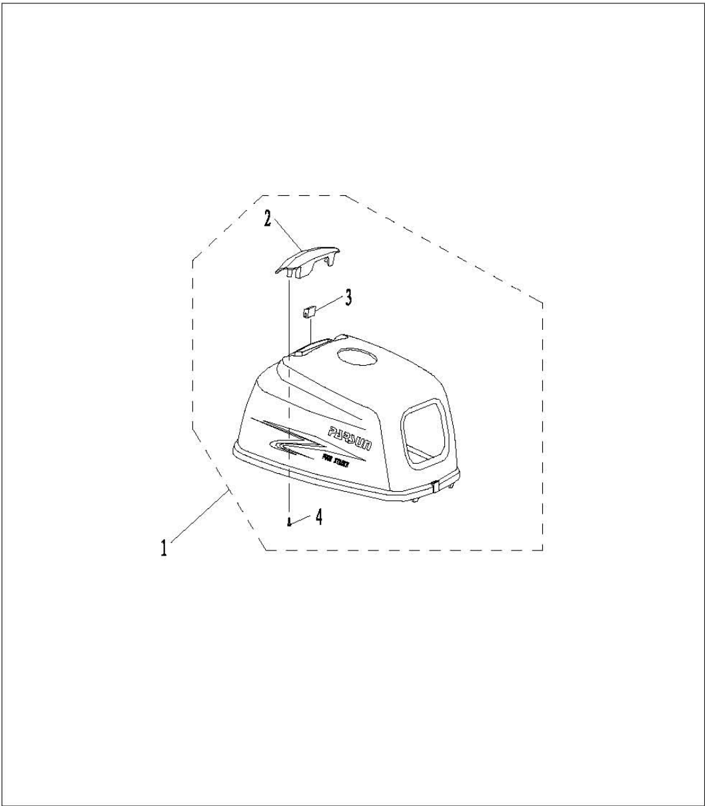
| 参照号码 SN. | 零件编号 PART NO. | 零件名称 DESCRIPTION | 数量 QTY | 备注 REMARKS |
|---|---|---|---|---|
| 1 | F2.6-06000001 | 顶罩 TOP COWLING | 1 | |
| 2 | F2.6-06000002 | 进气消音器 SILENCER,INTAKE | 1 | |
| 3 | F2.6-06000003 | 进气消音器减震块 DAMPERINTAIE SILENCBR | 1 | |
| 4 | GB/T845-85 | 十字槽盘头自攻蝶钉ST3.8x12 2SCREWTAPPING | 2 |
Disassembling and Inspection
- Removeintakesilencerbolt.
- Remove intake silencer and intake silencer damper..
- Inspect if top cowling, intake silencer and intake silencer damper are cracked or damaged. Replace ifnecessary.
Bottom Cowling
Explosive Drawing
Disassembling and inspection
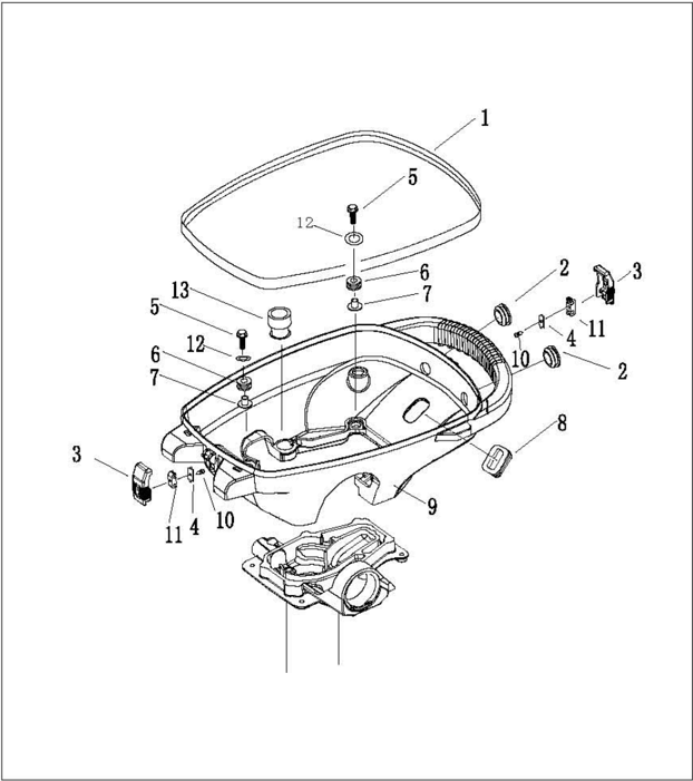
| 参照号码 SN. | PART NO. | 零件名称 DESCRIPTION | 数量 QTY | 备注 | REMARKS |
|---|---|---|---|---|---|
| 1 | F2.6-05000002 | 底罩密封条 | SEAL,BOTTOH COWLING 1 | ||
| 2 | F2.6-05000004 | 圆形闷头 | RUBBB PLUG,CIRCULAR 2 | ||
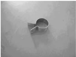
| 3 | F2.6-05000008 | 顶罩锁紧钩 | HOOK,LOCKING 2 | ||
| 4 | F2.6-05000010 | 金属连接杆 | METALLIC LINK ROD 2 | ||
| 5 | GB/T5783-2000 | 六角螺栓M6X25 | BOLT 4 | ||
| 6 | F2.6-05000006 | 底罩减震图 | DAMPEK 4 | ||
| F2.6-05000007 | 凸缘垫管 | TUBE FLANGB 4 | |||
| 8 | F2.6-05000003 | 长方形橡胶闷头 | RUBBER PLUG, QUADRATE 1 | ||
| 9 | F2.6-05000001 | 底罩 | BOTTON COFLING 1 | ||
| 10 | GB/T845-85 | 十字槽盘头自攻螺钉ST2.9XS SCHW,TAPPING | 2 | ||
| 11 | F2.6-05000009 | 锁紧钩连接件 | CONNECTER-KOD 2 | ||
| 12 | GB/T96-85 | 平垫圆6 | WASHER6 4 | ||
| 13 | F2.6-05000005 | 放油口胶套 | RUBBER LOYBR 1 |
- Removebottom-cowlingseal.
- Remove top cowling locking hook.
- Remove circular rubber plug and quadrate rubber plug.
- Inspect if bottom cowling is cracked or damaged.Replace if necessary.
- Inspect if top cowling locking hook is cracked or damaged.Replace if necessary.
Steering Handle
Explosive Drawing
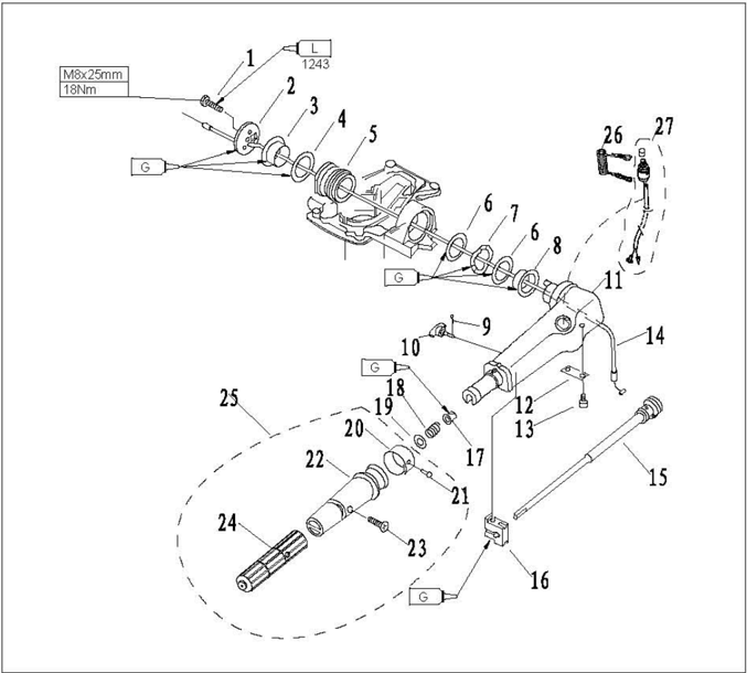
| 参照号码 SN. | 零件编号 PART NO. | 零件名称 DESCRIPTION | 数量 | 备注 REMARKS |
|---|---|---|---|---|
| 1 | CB/T5783-2000 | 六角螺栓M8x25 | BOLT | |
| 2 | F4-01000014 | 操舵手柄盖板 | COVER,HANDLE STEERING | |
| 3 | F4-01000008 | 操舵手柄衬套B | BUSH B,HANDLE | |
| 4 | F4-01000011 | 衬套整圈A | WASHER A,BUSH | |
| 5 | F4-05000014 | 操舵手柄减震器组件HANDLEDAMPERASSY | ||
| 6 | F4-01000010 | 衬套垫圈B | WASHER B,BUSH | |
| 7 | F4-01000012 | 手柄衬套波形垫圈 | BUSH,WAVE | |
| 8 | F4-01000009 | 操舵手柄衬套A | BUSH A,HANDLE | |
| 9 | CB/T91-86 | 开口销Φ1.6x12 | PIN,COTTER | |
| 10 | F4-01090200 | 阻力调整旋钮组件 | BOLT,FRICTIONADJUSTING |
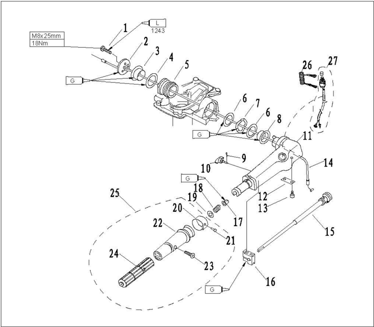
| 参照号码 SN. | 零件编号 PART NO. | 零件名称 DESCRIPTION | 数量 QTY HANDLE,STEERING | 备注 REMARKS |
|---|---|---|---|---|
| 11 | F4-01090001 | 操舵手柄 | 1 | |
| 12 | F4-01090002 | 节气门杆固定板 STAY | 1 | |
| 13 | GB/T818-85 | 十字槽盘头螺钉M5x12 SCREW,PAN HEAD | 2 | |
| 14 | F2.6-02010003 | 油门钢索组件 THROTTLE CABLEASSY | 1 | |
| 15 | F4-01090100 | 节气门杆组件 LEVER,THROTLLE ASSY | 1 | |
| 16 | F4-01090003 | 操舵手柄握把摩擦块FRICTION | 1 | |
| 17 | F4-01090006 | 衬套 BUSH | 1 | |
| 18 | F4-01090007 | 压缩弹簧 SPRING | 1 | |
| 19 | GB/T848-85 | 小垫圈10 WASHER | 1 | |
| 20 | F4-01090303 | 油门标志牌 INDICATOR,THROTTLE | 1 | |
| 21 | GB/T827-86 | 标牌铆钉Φ2x5 RIVET | 1 | |
| 22 | T15-01020301 | 操舵手柄望胶套 PLASTIC COVER,HANDLE | 1 | |
| 23 | GB/T820-85 | 十字槽半沉头螺钉M5x24SCREW | 1 | |
| 24 | T15-01020302 | 操舵手柄橡胶套 RUBBER COVER,HANDLE | 1 | |
| 25 | T15-01020300 | 操舵手柄塑胶套组件STEERING | 1 | |
| 26 | F4-01090401 | 引擎停止安全索 STOPER,HANG ROPE ASSY | 1 | |
| 27 | F2.6-02010200 | 急停开关组件 ENGINE STOP SWJTCH ASSY | 1 |
Disassembling and Inspection
- Remove steering cover.
- 2.Remove handle bush, bush washer and wave washer.
- Remove steering handle damper assembly.
- Removefriction adjustingbolt.
- Remove steering handle.
- Remove throttle cable.
- Remove throttle lever stay and throttle lever.
- Remove engine stop switch.
- Inspect if steering handle is cracked or damaged. Replace if necessary.
- a e necessary.
- Inspect if steering handle damper is cracked or damaged. Replace if necessary.
- Inspect if throttle cable is cracked or damaged.Replace if necessary.
- Inspect the conduction of engine stop switch.If not to specification, replace it.
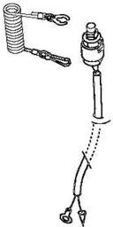
Remove lockplate:
Conducting
Install lockplate:
Not conducting
Push stop switch button: Conducting
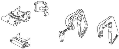
Bracket
Explosive drawing

| 参照号码 SN. | 零件编号 PART NO. | 零件名称 DESCRIPT10N | 零件名称 DESCRIPT10N | 数量 QTY | 备注 REMARKS |
|---|---|---|---|---|---|
| 1 | CB/T875-86 | 扁平头半空心铆钉4x11 | RIVET | 1 | |
| 2 | F4-01060002 | 锁紧手柄 | CLAMP HANDLE | 1 | |
| 3 | F2.6-01050101 | 锁紧手柄螺杆 | LOCKED SCREW | 1 | |
| 4 | F2.6-01050002 | 压缩弹簧 | SPRING | 1 | |
| 5 | F2.6-01050001 | 族转支架盖 | COVER,SWIVEL BRACKET | 1 | |
| 6 | F2.6-00000101 | 托架护盖 | COVER,BRACKET | 1 | |
| 7 | CB/T818-2000 | 十字槽盘头螺钉M6x16 | SCREW,PAN HEAD | 2 | |
| 8 | CB/T97.1-85 | 平垫圈6 | WASHER | 6 | |
| 9 | CB/T5783-2000 | 六角螺栓M6x30 | BOLT | 4 | |
| 10 | F2.6-01050200 | 锁紧块组件 | LOCKED BLOCK ASSY | 1 | |
| 11 | F2.6-01000003 | 旋转支架衬套A | BUSHING A | 1 | |
| 12 | F2.6-01000004 | 旋转支架衬套B | BUSHINGB | 1 | |
| 13 | F2.6-01050100 | 锁紧手柄组件 | LOCKED HANDLE ASSY | 1 | |
| 14 | F2.6-01040100 | 承推减震器 | DAMPER | 1 |

| SN. | 零件编号 PART NO. | 零件名称 DESCRIPTION | 数量 QTY | 备注 REMARKS | |
|---|---|---|---|---|---|
| 15 | F2.6-01040001 | 承推托架 | BRACKET,THRUST RECEIVE | 1 | |
| 16 | F2.6-01030007 | 起翘块 | LEVER | 1 | |
| 17 | F2.6-01030100 | 角度锁紧手柄组件 | TILT CLAMP HANDLE ASSY | 1 | |
| 18 | F4-01090006 | 衬套 | BUSHING | 1 | |
| 19 | F2.6-01030003 | 角度锁紧手柄钮簧 | SPRING | 1 | |
| 20 | F2.6-01030004 | 角度定位件 | LEVER,TILT LOCK | 1 | |
| 21 | CB/T879.2-200 | 轻型直槽弹性圆柱销2x10PIN | 1 | ||
| 22 | GB/T7940.1-95 | 直通式压注油杯M6 | NIPPLE,CREASE | 1 | |
| 23 | F2.6-01030001 | 旋转支架座 | BRACKET,SWIVEL | 1 | |
| 24 | F2.6-01030005 | 定位件连杆 | ROD,TILT LOCK | 1 | |
| 25 | GB/T896-86 | 开口档圈3.5 | CLIP | 1 | |
| 26 | F2.6-01030006 | 起翘块销轴 | PIN | 1 | |
| 27 | F2.6-01000001 | 六角螺栓M8x135 | BOLT | 1 | |
| 28 | CB/T6172.1-85 | 六角薄螺母M8 | NUT | 1 |

| 参照号码 SN. | 零件编号 PART NO. | 零件名称 DESCRIPTION | 零件名称 DESCRIPTION | 数量 QTY | 备注 REMARKS |
|---|---|---|---|---|---|
| 29 | CB/T6170-85 | 六角螺母M8 | NUT | 1 | |
| 30 | CB/T96-1985 | 大垫圈8 | WASHER | 2 | |
| 31 | F2.6-01010000 | 左夹紧托架组件 | BRACKET LEFT ASSY | 1 | |
| 32 | F2.6-01020000 | 右夹紧托架组件 | BRACKET RIGHT ASSY | 1 | |
| 33 | F4-01010005 | 板夹紧手柄铆钉 | RIVET | 2 | |
| 34 | F4-01010002 | 板夹紧螺杆 | CLAMP BOLT | 2 | |
| 35 | F4-01010004 | 板夹紧手柄 | CLAMP SHIPBOARD HANDLE | 2 | |
| 36 | F4-01010003 | 板夹紧圆盘 | CLAMP PLATE | 2 | |
| 37 | F2.6-01000002 | 螺栓垫管 | BUSH,BOLT | 1 | |
| 38 | GB/T889.1-2000 | 非金属嵌件六角锁紧螺母M6NUT | 非金属嵌件六角锁紧螺母M6NUT | 1 | |
| 39 | F2.6-01010001 | 左夹紧托架 | BRACKET,CLAMP(LEFT) | 1 | |
| 40 | CB/T5782-2000 | 六角螺栓M6x125 | BOLT | 1 | |
| 41 | F2.6-00000100 | 托架护盖组件 | BRACKET COVER ASSY | 1 | |
| 42 | F2.6-01040000 | 承推托架组件 | THRUST RECEIVE ASSY | 1 | |
| 43 | F2.6-00000102 | 护盖衬管 | BUSH | 1 |
Disassembling and Inspection
- 1.Remove clamp handle and bracket cover.
- 2.Remove swivel bracket cover.
- 3.Remove swivel bracket bushing and damper.
- 4.Remove clamp bracket
- 5.Remove swivel bracket.
- 6.Remove title clamp handle and title lock lever.
- Inspect the the swivel bracket and clamp bracket for damage or crack. Replace if necessary.
- Inspect swivel bracket bushing and damper for damage or crack. Replace if necessary.
- Inspect whether title clamp handle and title lock lever are deformed or damaged. Replace if necessary.


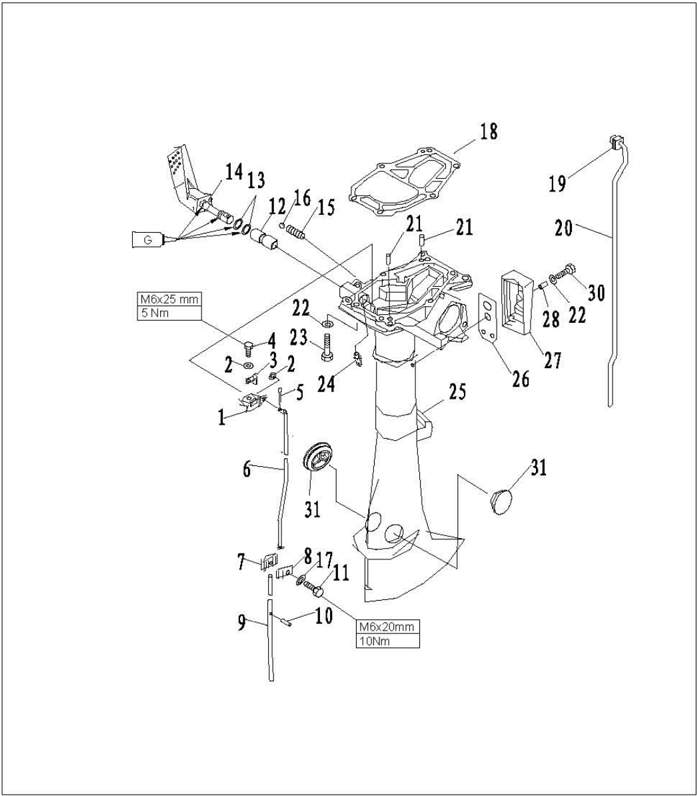
Upper Unit Explosive Drawing

| 参照号码 SN. | 零件编号 PART NO. | 零件名称 DESCRIPTION | 零件名称 DESCRIPTION | 数量 QTY | 备注 REMARKS |
|---|---|---|---|---|---|
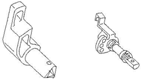
| 1 | F2.6-02000006 | 变档连杆支架 | LEVEL,SHIFT ROD | 1 | |
| 2 | GB/T97.1-85 | 平垫圈5 | WASHER | 3 | |
| 3 | F2. 6-02000008 | 变档手柄限位件 | WASHER,SHIFT ROD LEVER | ||
| 4 | GB/T5783-2000 | 六角螺栓M5x12 | BOLT | 1 | |
| 5 | GB/T91-86 | 开口销1.6x12 | PIN,COTTER | 1 | |
| 6 | F2.6-02000007 | 变档连杆 | ROD SHIFT | 1 | |
| 7 | F2.6-00000001 | 变档连接器A | CONNECTOR,SHIFT ROD A | 1 | |
| 8 | F2.6-00000002 | 变档连接器B | CONNECTOR,SHIFT ROD B | ||
| 9 | F2.6-03000005 | 变档凸轮轴 | SHIFT CAMSHAFT | 1 | |
| 10 | GB/T879.2-2000 | 轻型直槽弹性圆柱销2.5x14PIN | 1 | ||
| 11 | GB/T5783-2000 | 六角螺栓M6x20 | BOLT | 1 | |
| 12 | F4-02000002 | 水上装置壳体铜套 | BUSHINC,SHIFT ROD LEVER | 1 | |
| 13 | JISB2401 | 0形密封圈P9 | O-RING | 2 | |
| 14 | F2.6-02020000 | 变档手柄组件 | CEAE SHIFT HANDLE ASSY | 1 |

| 参照号码 SH. | 零件编号 PART NO. | 零件名称 DESCRIPTION | 零件名称 DESCRIPTION | 数量 QTY | 备注 REMARKS |
|---|---|---|---|---|---|
| 15 | F4-02000003 | 变档弹簧 | SPRING,GEAR | 1 | |
| 16 | GB308-84 | 钢珠8 | BALL8 | 1 | |
| 17 | F4-00000005 | 大垫圈 | WASHER | 1 | |
| 18 | F2.6-00000003 | 发动机密封垫 | GASKET,ENGINE | 1 | |
| 19 | F4-02040002 | 工形橡胶圈 | I-SHAPED RUBBER BAND | 1 | |
| 20 | F2.6-02000003 | 进水管 | WATER TUBE | 1 | |
| 21 | F15-0000013 | 定位销4x12 | PIN | 2 | |
| 22 | CB/T97.1-85 | 平垫圈6 | WASHER | 7 | |
| 23 | CB/T5783-2000 | 六角螺栓M6x35 | BOLT | 6 | |
| 24 | CB/T7940.1-95 | 直通压注油杯M6 | GREASE CUP | 1 | |
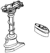
| 25 | F2.6-02000001 | 水上装置壳体 | UPPER CASING | 1 | |
| 26 | F2.6-02000005 | 排气盖板垫 | GASKET,EXHAUST COVER | 1 | |
| 27 | F2.6-02000004 | 排气盖板 | EXHAUST COVER | 1 | |
| 28 | F2.6-00000102 | 护盖衬管 | BUSH | 1 |
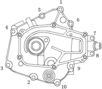
Disassembling and inspection
| 参照号码 SN. | 零件编号 PART NO. | 零件名称 DESCRIPTI0N | 数量 QTY | 备注 REMARKS |
|---|---|---|---|---|
| 29 | CB/T818-2000 | 十字槽盘头螺钉M6x16 SCREW | ||
| 30 | F4-02000012 | 水上装置橡胶堵头 RUBBER PLUG,UPPER | 2 |
- 1.Remove the water tube.
- 2.Remove gear shift handle assembly.
- 3.Remove the shift rod and shift rod lever.
- 4.Remove exhaust cover.
- Check upper casing for crack or wear. Replace if necessary.
- 6.Check gear shift handle for wear or damage.Replace if necessary.
- 7.Check exhaust cover for crack or wear. Replace if necessary.
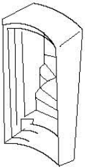
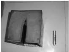
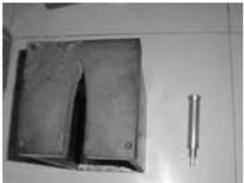
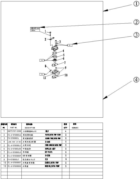
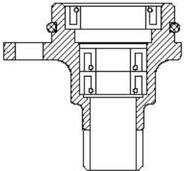
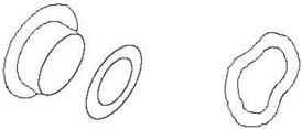
Water Pump Assembly
Explosive Drawing
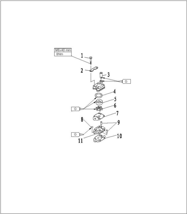
| 参用号码 SN. | 零件编号 PART NO. | 零件名称 DESCRIPTI0N | 零件名称 DESCRIPTI0N | 数量 QTY | 号 RBMARKS |
|---|---|---|---|---|---|
| 1 | CB/T5783-2000 | 六角螺栓M6x40 | BOLT | 4 | |
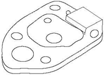
| 2 | F2.6-03000016 | 泵壳固定板 | PLATE, WATBR PUP FIXED | 2 | |
| 3 | F4-03000021 | 泵壳橡胶管 | RUBBER TUBE,FATER POMP | 1 | |
| 4 | JASO 19-033 | 水泵内壳0形圈 | O-RING | 1 | |
| 5 | F2.6-03000015 | 水泵内壳 | INNERHOSING,TATER PUNP | 1 | |
| 6 | F2.6-03000100 | 叶轮组件 | IMPELLER ASSY | ||
| 7 | F2.6-03000010 | 外档板 | OUT PLATB | 1 | |
| 8 | F2.6-03000009 | 0形密封圈 | O-RING | 1 | |
| 9 | F4-03000013 | 定位销Φ4x18 | PIK | 2 | |
| 10 | F2.6-03000007 | 水泵座密封垫 | GASET,WATER PUP | 1 | |
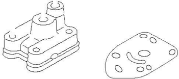
| 11 | F2.6-03000008水泵座 | EOUSING,ATBR PUMP | 1 |
Disassembling and Inspection
- Remove water pump fixed plate.
- Removewaterpumphousing
- Remove impeller, inner housing and O ring of water pump inner housing.
- Removewaterpumpbase.
- Check water pump housing and out plate for crack, crank or damage.Replace if necessary.
- Check inner water pump housing and impeller for crack, deform, burn or damage. Replace if necessary.
- 7.Check water pump base for crack, crank, scratch or damage. Replace if necessary.

Lower Unit Explosive Drawing
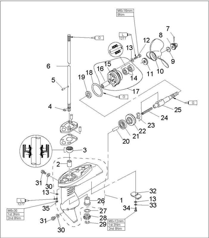
| SN. | 零件编号 PART NO. | 零件名称 DESCRIPTION | 零件名称 DESCRIPTION | 数量 QTY | 备注 REMARKS |
|---|---|---|---|---|---|
| 1 | F2.6-03000001 | 水下装置壳体 | LOWER CASING | 1 | |
| 2 | F2.6-03000003 | 不带档边筒形轴承 | BEARING | 1 | |
| 3 | F2.6-03000004 | 驱动轴下油封9.8x24x9 | OIL SEAL | 1 | |
| 4 | F2.6-03000012 | 轴用钢丝档圈 | CLIP | 1 | |
| 5 | F2.6-03000013 | 叶轮定位销Φ3.5x7 | PIN | 1 | |
| 6 | F2.6-03000011 | 驱动轴 | DRIVE SHAFT | 1 | |
| 7 | GB/T91-86 | 开口销2.5x30 | PIN,COTTER | 1 | |
| 8 | F4-03080000 | 螺母组件 | NUT ASSY | 1 | |
| 9 | F4-03000026 | 不锈钢垫片 | WASHER | 1 | |
| 10 | F2.6-03010000 | 螺旋案组件 | PROPELLER ASSY | 1 | |
| 11 | F4-03000025 | 不锈钢垫块 | SPACER | 1 | |
| 12 | GB/T5783-2000六角螺栓M6x16 | BOLT | 2 | ||
| 13 | GB/T97.1-85 | 平垫圈6 | WASHER | 2 | |
| 14 | F4-03050002 | 螺旋桨轴油封13x22x7 | OIL SEAL | 2 |

| 参照号码 SN. | 零件编号 PART NO. | 零件名称 DESCRIPTION | 零件名称 DESCRIPTION | 数量 QTY | 备注 REMARKS |
|---|---|---|---|---|---|
| 15 | F2.6-03000301 | 水下装置壳体盖 | COVER,LOWER CASING | 1 | |
| 16 | F2.6-03000302 | 筒形轴承 | BEARING,SLEEVE | 1 | |
| 17 | F2.6-03000300 | 水下装置壳体盖组件 | COVER ASSY,LOWER CASING | 1 | |
| 18 | JISB2401 P48 | 水下壳体盖0形圈Φ47.1x3.5 | O-RING | 1 | |
| 19 | F2.6-03000021 | 驱动轴垫圈 | WASHER | 1 | |
| 20 | F2.6-03000020 | 变档柱塞 | PLUG,SHIFT | 1 | |
| 21 | NTN6003EY | 深沟球轴承 | BALL BEARING | 1 | |
| 22 | F2.6-03000019 | 正档齿轮组件 | POSITIVE CEAR ASSY | 1 | |
| 23 | F2.6-03000202 | 离合器块 | CLUTCH BLOCK | 1 | |
| 24 | F4-03030003 | 离合器块压簧 | SPRINC,CLUTCH BLOCK | 1 | |
| 25 | F2.6-030000201螺旋浆轴 | SHAFT,PROPELLER | 1 | ||
| 26 | F2.6-03000002 | 带档边筒形轴承 | BEARING | 1 | |
| 27 | F2.6-03000017 | 主动轮填隙片(T:2.0毫米) | SHIM(T: 2. 0MM) | 1 | |
| 28 | F2.6-03000018 | 主动齿轮 | INITIATIRE CEAR | 1 |

| 参照号码 SN. | 零件编号 PART NO. | 零件名称 DESCRIPTION | 数量 QTY | 备注 | REMARKS |
|---|---|---|---|---|---|
| 29 | CB/T896-86 | 开口档圈6 | CIRCLIP | ||
| 30 | F4-03000024 | 注油孔螺塞垫 | GASKET | ||
| 31 | F4-03000023 | 注油孔螺塞 | PLUG,OIL HOLE | ||
| 32 | F4-03000022 | 阳极 | ANODE | ||
| 33 | CB/T861.1-87 | 内齿锁紧垫圈6 | WASHER,INTERNAL TOOCH | ||
| 34 | CB/T5783-2000 | 六角螺栓M6x12 | BOLT | ||
| 35 | CB/T5783-2000 | 0六角螺栓M6x30 | BOLT |
Disassembling and Inspection
- Remove cotter pin, nut assy, and spacer.
- 2.Remove propeller assembly and spacer.
- 3.Remove the lower casing cover.
- Remove drive shaft, positive gear assy, and shift plug.
- 5.Remove shift rod cam assy and drive shaft.
- Remove sleeve bearing with guard board.
- Remove sleeve bearing without guard board by using sleeve bearing installer tool.
- 8.Remove the clutch block from the propeller shaft.
Propeller Shaft and Clutch Block
- Check clutch block for wear or damage. Replace if necessary.
- Check propeller shaft for wear or damage. Replace if necessary.
Clutch Block Installation
- Put clutch block spring into the hole of the propeller shaft tail.
- 2.Install the clutch block as shown.Take note ofthe direction.
Lower Casing Cover
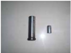
- Check bearing for rust or rumbling when run. Replace if necessarily.
- Remove bearing and oil seal by bearing puller.
Note:
Don't remove bearing unless change it.
- Clean casing cover by a soft brush and solvent.
- Check casing cover for crack or damage. Replace if necessary.
Install oil seal.
Note:
Please use special tool to install oil seal and bearing.
Sleeve Bearing
Drive Shaft
Inspect the drive shaft for crank or wear. Replace if necessary.
Gear
Forward Gear Bearing
Inspect bearing for rust and rumbling when rotating.Replace if necessary.
Lower Unit Casing
- Inspect lower casing cover for crack or damage.Check if the cooling water inlet is blocked. Replace if necessary.
- tools.

Sleeve bearing with guard board installer tool
Lower casing bracket and sleeve bearing w ithout guard board installer tool
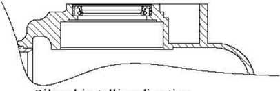
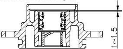
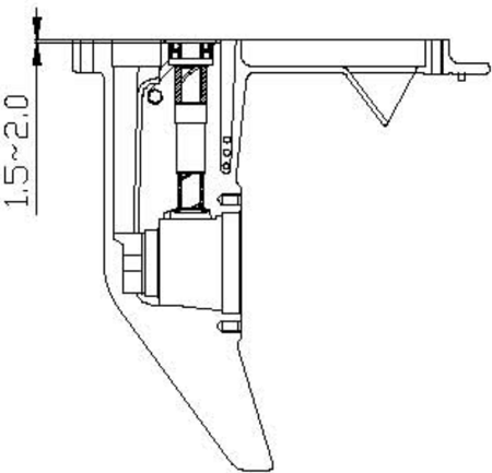
- 3.Install new oil seal, with the depth as shown. (unit: mm)
Inspect sleeve bearing with guard board and sleeve bearing without guard board for wear, crack or damage.Replace if necessary.

Lower Casing Cover Oil Seal and Bearing Installation

Lower casing bracket and drive shaft oil seal installer tool
Common Troubles and Solutions
| Trouble type | Possible reason | Recovery action |
|---|---|---|
| Starter will not operate | Starter components arefaulty | Repair or replace |
| Engine will not start (starter operates) | Fuel tank is empty Fuel contaminated orstale | Fill tankwith clean,freshfuel |
| Engine will not start (starter operates) | Airvent screwnotloosened | Loosen air vent screw |
| Engine will not start (starter operates) | Spark plug(s) fouled or of incorrect type. | Inspect spark plug(s). Clean or replace with recommended type |
| Engine will not start (starter operates) | Spark plug cap(s)fitted incorrectly | Check and re-fit cap(s) |
| Engine will not start (starter operates) | Ignition wiring damaged or poorly connected | Check wires for wear or breaks. Tighten all loose connections.Replace worn or broken wires |
| Engine will not start (starter operates) | Ignition parts are faulty | Replace |
| Engine will not start (starter operates) | Engine stop switch lanyard is not attached | Attach lanyard |
| Engine will not start (starter operates) | Engine inner parts are damaged | Repair |
| Engine will not start (starter operates) | Valve gap is incorrect | Inspect and adjust as specified |
| Engine idles irregularly or stalls | Spark plug(s) fouled or of incorrect type. | Inspect spark plug(s).Clean or replace withrecommended type |
| Engine idles irregularly or stalls | Fuel system is obstructed | Check for pinched or kinked fuel line or otherobstructionsinfuelsystem |
| Engine idles irregularly or stalls | Fuel is contaminated or stale | Fill tank with clean, fresh fuel |
| Engine idles irregularly or stalls | Spark plug gap is incorrect | Inspect and adjust as specified |
| Engine idles irregularly or stalls | Ignition wiring damaged or poorly connected | Check wires for wear or breaks.Tighten all loose connections. Replace worn or broken wires |
| Engine idles irregularly or stalls | Specified engine oil is not being used | Check and replace oil as specified |
| Engine idles irregularly or stalls | Thermostat isfaulty or clogged | Replace |
| Engine idles irregularly or stalls | Carburetor adjustments areincorrect | Replace |
| Engine idles irregularly or stalls | Airvent screw on fuel tankis closed | Loosen airvent screw |
| Engine idles irregularly or stalls | Throttle cable adjustments is incorrect | Adjust correctly |
| Engine idles irregularly or stalls | Chokeknobispulled out | Return to home position |
| Engine idles irregularly or stalls | Motor angle is toohigh | Return to normal operating position |
| Engine power loss | Propeller is damaged | Repair orreplace propeller |
| Engine power loss | Trim angle is incorrect | Adjust trim angle to achieve most efficient operation |
| Engine power loss | Motor is mounted at incorrect transom height | Adjustmotor to proper transomheight |
| Engine power loss | Boatbottom isfouledwith marine growth | Cleanboatbottom |
| Engine power loss | Weeds or other foreign matter are tangled on gear housing | Removeforeignmatter and clean lower unit |
| Engine power loss | Fuel system isobstructed | Check for pinched or kinked fuel line or otherobstructions infuel system |
| Engine power loss | Fuel orstale | Fill tankwith clean,fresh fuel |
| Engine power loss | Spark plug gap is incorrect | Inspect and adjust as specified |
| Engine power loss | Ignition wiring is damaged or poorly connected | Check wires for wear or breaks.Tighten all loose connections.Replace worn or broken wires |
| Engine power loss | Ignition parts have failed | Replace |
| Engine power loss | Specified engine oil is not being used or oil is added toomuch | Check and replace oil as specified,or adjust engine oil to specified position |
| Engine power loss | Thermostatisfaulty | Replace |
| Engine power loss | Fuel jointconnection is incorrect | Connect correctly |
| Engine power loss | Specified spark plug(s) are not being used | Checkandreplace spark plug(s)as specified |
| Engine vibrates excessively | Propeller is damaged | Repair or replace propeller |
| Engine vibrates excessively | Propeller shaft is damaged | Replace |
| Engine vibrates excessively | Weeds or other foreign matter are tangled on propeller | Remove and cleanpropeller |
| Engine vibrates excessively | Motor mountingbolt isloose | Tighten bolt |
| Engine vibrates excessively | Steering pivot is loose | Tighten steering pivot |
| Engine vibrates excessively | Steering is damaged | Replace |