
Servisná príručka prívesného motora Parsun F20/F25
Obsah
Všeobecné informácie
Identifikácia
Sériové číslo prívesného motora je uvedené na štítku. Štítok sa nachádza na ľavej zostave konzoly alebo na hornej časti otočnej konzoly. Zapíšte sériové číslo prívesného motora do určených polí, aby ste si uľahčili objednávanie náhradných dielov u predajcu Parsun alebo ho mali k dispozícii pri odcudzení motora.
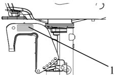
1
- Umiestnenie výrobného čísla prívesného motora

Výrobné číslo má nasledujúci formát:
Č.
PORADOVÉ ČÍSLO VÝROBNEJ SÉRIE MOTORA
VÝROBNÝ KÓD
Výber vrtule
Výkon prívesného motora zásadne ovplyvňuje výber vrtule, pretože nesprávny výber môže výkon zhoršiť.
Pri väčšom zaťažení člna a nízkych otáčkach motora je vhodnejšia lodná skrutka s menším stúpaním. Naopak, lodná skrutka s väčším stúpaním je vhodnejšia pri menšom prevádzkovom zaťažení, pretože umožňuje udržiavať správne otáčky motora.
Pri chode motora s úplne otvorenou škrtiacou klapkou sa má použiť lodná skrutka vhodná pre otáčky motora a kapacitu prívodu paliva. Tak môže prívesný motor dosahovať najlepší výkon.
| Rozmery vrtule | Materiál |
|---|---|
| 3-9 " 8 7 ×8 | Hliníková zliatina |
| 3-9 " 8 7 ×9 | Hliníková zliatina |
| 3-9 " 8 7 ×10 " 2 1 | Hliníková zliatina |
| 3-9 " 8 7 ×11 " 4 1 | Hliníková zliatina |
| 3-9 " 8 7 ×12 | Hliníková zliatina |
| 3-9 " 8 7 ×13 | Hliníková zliatina |
| 3-9 " 8 7 ×14 | Hliníková zliatina |

Núdzové štartovanie
Ak štartovacie zariadenie nefunguje, motor možno naštartovať pomocou núdzového štartovacieho lanka.
VAROVANIE:
- Tento postup štartovania možno použiť iba v núdzi a na návrat do prístavu na opravu.
- Pri štartovaní motora núdzovým štartovacím lankom ochrana proti štartovaniu so zaradeným prevodom nefunguje. Preto sa uistite, že radiaca tyč je v polohe NEUTRÁL.
- Uistite sa, že za vami nikto nestojí, aby ho vytiahnuté lanko nezranilo.
- Po naštartovaní motora nemontujte štartovacie zariadenie ani horný kryt. Odevy a iné predmety držte v dostatočnej vzdialenosti. Nedotýkajte sa zotrvačníka ani iných pohyblivých častí.
- Počas štartovania a prevádzky sa nedotýkajte zapaľovacej cievky, koncovky sviečky ani iných elektrických častí.
Postup je nasledovný:
- Odstráňte horný kryt motora.
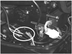
- Odpojte lanko zariadenia na ochranu proti štartovaniu so zaradeným prevodom.
- Lanko zariadenia ochrany proti štartovaniu so zaradenou rýchlosťou
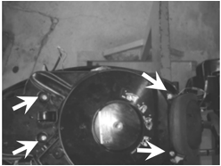
- Demontujte tri skrutky, odpojte kontrolku alarmu a odstráňte štartér.
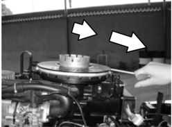
- Vložte uzol lanka do zárezu rotora zotrvačníka a niekoľkokrát oviňte lanko okolo zotrvačníka v smere hodinových ručičiek.
- Pomaly ťahajte rukoväť ručného štartéra, kým nepocítite odpor.
- Silným potiahnutím naštartujte motor. V prípade potreby zopakujte.

Bezpečnosť pri práci
Dodržiavajte nasledujúce bezpečnostné postupy, aby ste predišli nebezpečenstvu a úrazom pri údržbe a opravách a zlepšili efektivitu práce.
1. Prevencia požiaru
Benzín, mazací olej a mazivo sú veľmi horľavé. Pri práci ich držte mimo dosahu tepla, iskier a otvoreného ohňa.
2. Vetranie
Ropné výpary a výfukové plyny motora sú veľmi toxické. Ich vdychovanie je škodlivé a pri veľkých množstvách smrteľné. Pri skúšobnom chode motora v interiéri zabezpečte dobré vetranie.
3. Osobná ochrana
Pri vŕtaní, brúsení alebo práci so vzduchovým kompresorom si chráňte oči vhodnými bezpečnostnými alebo ochrannými okuliarmi. V prípade potreby chráňte ruky a nohy ochranným pracovným odevom, bezpečnostnými rukavicami a obuvou.
4. Mazivá a tesniace kvapaliny
Pri údržbe a opravách prívesných motorov Parsun používajte iba výrobky dodávané alebo odporúčané našou spoločnosťou.
Za bežných podmienok používania by mazivá uvedené v tejto príručke nemali predstavovať nebezpečenstvo. Bezpečnosť je však prvoradá a dodržiavaním správnych bezpečnostných postupov sa všetky riziká minimalizujú.
- 1 Na ochranu pokožky sa odporúča pred prácou naniesť na ruky vhodný ochranný krém.
- 2 Odev znečistený mazivami čo najskôr vymeňte a pred ďalším použitím vyperte.
- 3 Vyhnite sa kontaktu pokožky s mazivami.
- 4 Ruky a ostatné časti tela, ktoré prišli do styku s mazivami alebo odevom znečisteným mazivami, čo najskôr dôkladne umyte teplou vodou a mydlom.
- 5 Majte k dispozícii čisté handry nepúšťajúce vlákna na utieranie vytečeného oleja alebo maziva.
5. Správne pracovné postupy
- 1 Dodržiavajte pokyny pre uťahovací moment. Pri uťahovaní skrutiek a matíc najprv uťahujte väčšie rozmery a vnútorné upevňovacie prvky pred vonkajšími.
- 2 Používajte odporúčané špeciálne náradie na ochranu dielov pred poškodením. Správne používajte vhodné náradie.
Demontáž a montáž
Pri demontáži a montáži dodržiavajte tieto zásady:
- Pri demontáži a montáži používajte špeciálne nástroje.
- Pred demontážou dielov odstráňte nečistoty.
- Pred montážou naolejujte kontaktné plochy pohyblivých dielov.
- Namontujte ložisko s označením výrobcu na predpísanej strane a dôkladne ho namažte olejom.
- Pri montáži olejových tesnení naneste tenkú vrstvu vodoodolného maziva na tesniaci okraj a vonkajší priemer.
- Po montáži skontrolujte, či pohyblivé diely fungujú normálne.
Diely na jednorazové použitie
Diely na jednorazové použitie zahŕňajú tesnenia, olejové tesnenia, O-krúžky, závlačky, pružiny, krúžky a podobne. Pri opätovnej montáži prívesného motora ich musíte vymeniť.
Kontrola pred dodaním
Na zabezpečenie správneho používania pred dodaním skontrolujte nasledujúce položky.
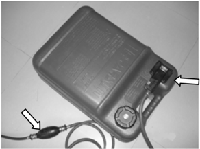
- KONTROLA PALIVOVÉHO SYSTÉMU Skontrolujte, či je palivové potrubie pevne pripojené a či je palivová nádrž naplnená palivom.
UPOZORNENIE:
V tomto 4-taktnom prívesnom motore nepoužívajte palivo vopred zmiešané s olejom.
2. Kontrola hladiny oleja
- 1 Skontrolujte hladinu motorového oleja Vyberte mierku oleja a skontrolujte hladinu motorového oleja..
Mierka oleja 2. Značka hornej hladiny 3. Značka dolnej hladiny
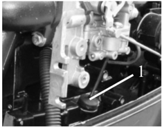
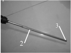
Hladina oleja musí byť medzi hornou a dolnou značkou. Ak je nad hornou značkou, vypustite motorový olej; ak je pod dolnou značkou, doplňte motorový olej po hornú značku.
- 2 Skontrolujte hladinu prevodového oleja; v takom prípade namontujte zátku hladiny oleja a utiahnite ju predpísaným momentom. V opačnom prípade doplňte
Odstráňte zátku hladiny oleja. Skontrolujte, či prevodový olej vyteká z otvoru na kontrolu hladiny. Ak prevodový olej.
- Zátka kontroly hladiny oleja

3. Kontrola riadenia
Skontrolujte, či je riadenie stabilné.
Skontrolujte správne nastavenie trenia riadenia. Otočte skrutku upínacej rukoväti v smere hodinových ručičiek, aby ste zvýšili odpor.
Otočte skrutku upínacej rukoväti proti smeru hodinových ručičiek, aby ste znížili odpor. 1. Skrutka upínacej rukoväti
4. Kontrola radiacej páky a plynu
Skontrolujte, či sa radiaca páka ovláda plynulo.
Skontrolujte, či sa plynová rukoväť plynulo otáča od úplne zatvorenej po úplne otvorenú polohu.
5. Kontrola vypínača motora
Skontrolujte, či sa motor zastaví po stlačení vypínača motora alebo vytiahnutí núdzového vypínacieho lanka.
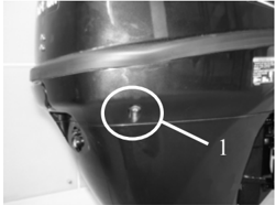
6. Kontrola kontrolného otvoru chladiacej vody
Pri bežiacom motore skontrolujte, či z kontrolného otvoru vyteká chladiaca voda.
- Kontrolný otvor chladiacej vody
7. Zábeh
- 1 Prvá 1 hodina: Motor prevádzkujte pri 2000 r/min alebo približne na polovičný plyn.
- ② Druhá hodina: Motor prevádzkujte pri 3000 r/min alebo približne na 3/4 plynu.
- ③ ? Nasledujúcich 8 hodín: Motor prevádzkujte nepretržite na plný plyn. Každý interval prevádzky nesmie prekročiť 5 minút.
8. Kontrola po zábehu
- 1 Skontrolujte, či prevodový olej obsahuje vodu.
- ② Skontrolujte, či palivová hadica netesní.
- ③ ? Po zábehu nechajte motor bežať na voľnobeh. Pomocou čistiaceho nástroja prepláchnite kanál chladiacej vody čistou sladkou vodou.
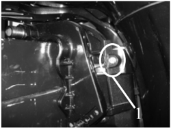
9. Po zábehu skontrolujte voľnobežné otáčky.
- ① Motor zahrievajte 5 minút.
- ② Pomocou otáčkomera zmerajte voľnobežné otáčky v RPM. Ak sú mimo špecifikácie, nastavte ich. Voľnobežné otáčky: 925~1025 r/min
- ③ Otočte dorazovú skrutku škrtiacej klapky v smere alebo proti smeru hodinových ručičiek, kým nedosiahnete predpísané voľnobežné otáčky. 1. Upevňovacia skrutka škrtiacej klapky
- ④ Po nastavení voľnobežných otáčok niekoľkokrát zvýšte otáčky, aby ste skontrolovali stabilitu motora.
Špeciálne nástroje a meracie zariadenia
Pri údržbe a opravách potrebujete rôzne špeciálne nástroje a meracie zariadenia. Správne nástroje zvýšia efektivitu práce a zabránia zraneniam osôb a poškodeniu prívesných motorov.
Špeciálne nástroje
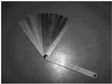

Mierka vôle Posúvač piesta


Kľúč na olejový filter Sťahovák ložísk
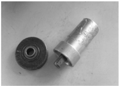
Prípravok na montáž ložiska krytu spodnej skrine

Nástroj na montáž zostavy krytu spodnej skrine
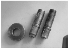
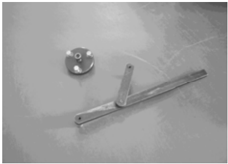
Držiak a sťahovák zotrvačníka

Stláčač ventilových pružín
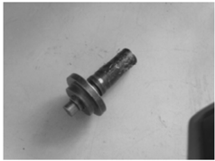
Nástroj na montáž olejového tesnenia krytu spodnej skrine Nástroj na montáž ihlového ložiska krytu spodnej skrine
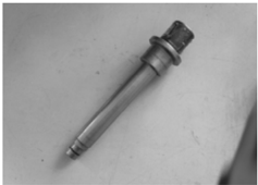

Nástroj na montáž ihlového ložiska spodnej skrine Nástroj na montáž skrine ložiska hnacieho hriadeľa
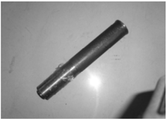
Nástroj na montáž ložiska hnacieho hriadeľa Nástroj na montáž olejového tesnenia ložiskového bloku
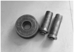
Nástroj na montáž skrine ložiska ozubeného kolesa chodu vpred
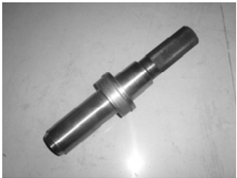
Meracie zariadenia
Nástroj na montáž ložiska ozubeného kolesa spätného chodu
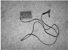
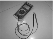
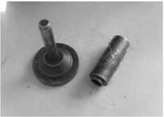
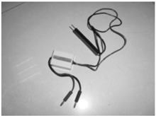
Digitálny otáčkomer Digitálny multimeter Adaptér špičkového napätia
Rozložený výkres a symboly
Rozložený výkres
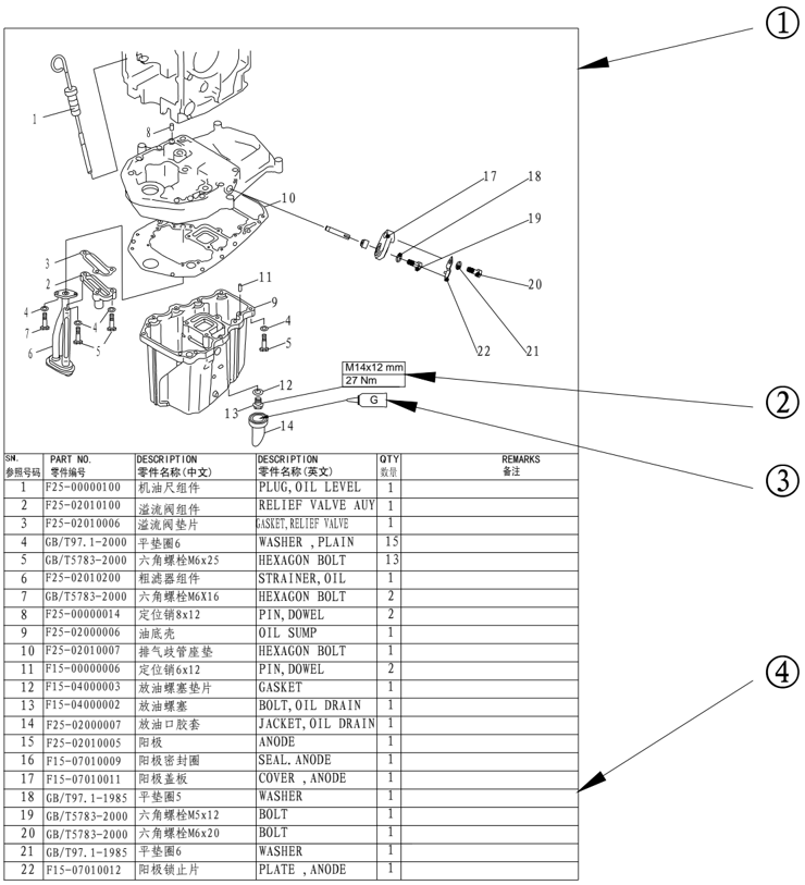
- ① Rozložený výkres dielov
- ② Špecifikácia skrutky a predpísaný uťahovací moment
- ③ Miesto nanesenia oleja, tekutého tesniaceho alebo zaisťovacieho prípravku
- ④ Podrobnosti náhradných dielov
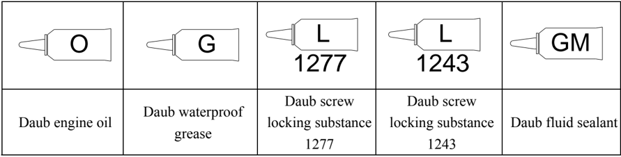
Symboly
Špecifikácie
Špecifikácie prívesného motora
| Položka | Položka | Položka | Popis | Položka | Položka | Popis |
|---|---|---|---|---|---|---|
| Celková dĺžka (BM/FW) | Celková dĺžka (BM/FW) | 1151/703mm | Zapaľovací systém | C.D.I | ||
| Celková šírka (BM/FW) | Celková šírka (BM/FW) | 430/376mm | Systém obohacovania zmesi | Počiatočné obohatenie zmesi | ||
| Celková výška | S | 1153mm | Zapaľovacia sviečka | DPR7EA-9 | ||
| Celková výška | L | 1280mm | Výfukový systém | Cez náboj lodnej skrutky | ||
| Výška zrkadla člna | S | 381mm | Mazací systém | Tlakové mazanie | ||
| Výška zrkadla člna | L | 508mm | Typ paliva | Bežný bezolovnatý benzín | ||
| S (BM/FW) | S (BM/FW) | 66/68kg | Norma paliva | PON86 | ||
| L (BM/FW) | L (BM/FW) | 68/70kg | Odporúčaný motorový olej | API: SE, SF, SG, SH, SJ SAE: 10W30, 10W40 | ||
| Maximálny výkon | F20 | 14.7Kw@5500 r/min | Množstvo motorového oleja (pred výmenou olejového filtra) | 1.7L | ||
| Maximálny výkon | F25 | 18.4Kw@5500 r/min | Množstvo motorového oleja (pred výmenou olejového filtra) | 1.7L | ||
| Prevádzka na plný plyn | Prevádzka na plný plyn | 5000 6000 r/min | Odporúčaný prevodový olej | Hypoidný prevodový olej SAE #90 | ||
| Maximálna spotreba | F20 | 7.3L/h@6000 r/min | ||||
| paliva | F25 | 9.2L/h@6000 r/min | Množstvo prevodového oleja | 320 cm3 | ||
| Voľnobežné otáčky (neutrál) | Voľnobežné otáčky (neutrál) | 975±50 r/min | Uhol vyklápania | 8 o 12 o 16 o , 20 o , 24 o | ||
| Typ | Typ | 4-taktný, OHC | Uhol vyklopenia nahor | 64 o | ||
| Počet valcov | Počet valcov | 2 | Uhol riadenia | 45 o +45 o | ||
| Zdvihový objem | Zdvihový objem | 498cm³ | Polohy radenia | F-N-R | ||
| Vŕtanie×Zdvih | Vŕtanie×Zdvih | 65mm×75mm | Prevodový pomer | 2.08 | ||
| Kompresný pomer | Kompresný pomer | 9.87:1 | Typ prevodu | Kužeľové ozubené koleso so špirálovým ozubením | ||
| Min. kompresný tlak | Min. kompresný tlak | 810kPa | Typ spojky | Zubová spojka | ||
| Tlak maziva | Tlak maziva | 80kPa (voľnobežné otáčky) | Systém pohonu vrtule | Drážkovanie | ||
| Počet karburátorov | Počet karburátorov | 1 | Smer otáčania vrtule | V smere hodinových ručičiek (pohľad zozadu) |
| Ovládací systém | Ovládanie kormidlovou rukoväťou (BM) Diaľkové ovládanie (FW) |
|---|---|
| Štartovací systém | Lankové štartovanie (BM) Elektrické štartovanie (FW) |
Údaje o údržbe
Motorová jednotka
| Položka | Položka | Položka | Popis | Položka | Popis | |
|---|---|---|---|---|---|---|
| Hlava valca | Limit deformácie | Limit deformácie | 0.1mm | Ventilová vôľa | Sanie | 0.15~0.25mm |
| Hlava valca | Vnútorný priemer vačkového hriadeľa | Vnútorný priemer vačkového hriadeľa | 37.000~37.025mm | (za studena) | Výfuk | 0.25~0.35mm |
| Hlava valca | Vonkajší priemer hriadeľa vahadiel | Vonkajší priemer hriadeľa vahadiel | 15.971~15.991mm | Šírka plochy ventilu | Sanie | 1.84~2.97mm |
| Hlava valca | Vnútorný priemer vahadla | Vnútorný priemer vahadla | 16.000~16.018mm | Šírka plochy ventilu | Výfuk | 1.98~3.11mm |
| Valec | Vŕtanie | Vŕtanie | 65.00~65.015mm 65.1mm | šírka | Sanie | 0.9~1.1mm |
| Valec | Limit opotrebenia | Limit opotrebenia | Výfuk | 0.9~1.1mm | ||
| Valec | Limit kužeľovitosti | Limit kužeľovitosti | 0.08mm | Hrúbka okraja ventilu | Sanie | 0.8mm |
| Valec | Limit ovality | Limit ovality | 0.05mm | Hrúbka okraja ventilu | Výfuk | 0.9mm |
| Piest | Priemer piesta | Priemer piesta | 64.950~64.965mm Ventil | Priemer hlavy ventilu | Sanie | 31.9~32.1mm |
| Piest | Výška meracieho bodu | Výška meracieho bodu | 2mm (od spodnej časti piesta) | Priemer hlavy ventilu | Výfuk | 25.9~26.1mm |
| Piest | Vôľa medzi piestom a valcom | Vôľa medzi piestom a valcom | 0.035~0.065mm | Priemer drieku | Sanie | 5.475~5.490mm |
| Piest | Vnútorný priemer otvoru piestneho čapu | Vnútorný priemer otvoru piestneho čapu | 15.974~15.985mm | Priemer drieku | Výfuk | 5.460~5.475mm |
| Vonkajší priemer piestneho čapu | Vonkajší priemer piestneho čapu | Vonkajší priemer piestneho čapu | 15.965~15.970mm | Vnútorný priemer vodidla | Sanie | 5.500~5.512mm |
| Piestny krúžok | Horný krúžok | Hrúbka | 1.17~1.19mm | Vnútorný priemer vodidla | Výfuk | 5.500~5.512mm |
| Piestny krúžok | Šírka | 2.25~2.4mm | Vôľa medzi driekom a vodidlom | Vôľa medzi driekom a vodidlom | 0.025~0.052mm | |
| Piestny krúžok | Vôľa v zámku | 0.15~0.30mm | Limit kruhovitosti drieku | Limit kruhovitosti drieku | 0.03mm | |
| Piestny krúžok | Bočná vôľa | 0.02~0.06mm | Voľná dĺžka | Voľná dĺžka | 40.0mm | |
| Piestny krúžok | Hrúbka | 1.47~1.49mm Ventilová pružina | Limit voľnej dĺžky | Limit voľnej dĺžky | 38.4mm | |
| Piestny krúžok | Krúžok | Šírka | 2.60~2.80mm | Limit sklonu | Limit sklonu | 1.7mm |
| Piestny krúžok | č. 2 | Vôľa v zámku | 0.30~0.50mm ojnica | Vnútorný priemer malého oka ojnice. | Vnútorný priemer malého oka ojnice. | 15.985~15.998mm |
| Piestny krúžok | Bočná vôľa | 0.02~0.06mm Ojnica | Vnútorný priemer veľkého oka ojnice. | Vnútorný priemer veľkého oka ojnice. | 36.000~36.016mm | |
| Piestny krúžok | Krúžok | Hrúbka | 2.36~2.48mm | Olejová vôľa veľkého oka ojnice | Olejová vôľa veľkého oka ojnice | 0.020~0.052mm |
| Piestny krúžok | olejom. | Šírka | 2.75mm | Veľké oko ojnice | A (čierna) | 1.496~1.490mm |
| Vôľa v zámku | 0.20~0.70mm | hrúbka ložiska | B (hnedá) | 1.490~1.484mm | ||
|---|---|---|---|---|---|---|
| Bočná vôľa | 0.04~0.18mm | Priemer čapu | Priemer čapu | 42.984~43.000mm | ||
| Výška | Sanie | 30.834~31.034mm | Priemer ojničného čapu | Priemer ojničného čapu | 32.984~33.000mm | |
| Výfuk | 30.834~31.034mm | Šírka ojničného čapu | Šírka ojničného čapu | 21.00~21.07mm | ||
| Priemer základnej kružnice | Priemer základnej kružnice | 25.90~26.10mm | Bočná vôľa veľkého oka | Bočná vôľa veľkého oka | 0.05~0.22mm | |
| Čap | Horný | 36.925~36.945mm | Limit ovality | Limit ovality | 0.05mm | |
| priemer | Stredný | 36.935~36.955mm | Termostat | Teplota otvorenia | Teplota otvorenia | 58~62ºC |
| Limit ovality | Limit ovality | 0.03mm | Termostat | Teplota úplného otvorenia | Teplota úplného otvorenia | 70ºC |
| Olejová vôľa čapu | Olejová vôľa čapu | 0.050~0.090mm | Termostat | Výška zdvihu ventilu | Výška zdvihu ventilu | 3mm |
| Typ | Typ | Gerotorové čerpadlo | Palivové čerpadlo | Zdvihový objem | Zdvihový objem | 70L@3000 r/min |
| Otvárací tlak bezpečnostného ventilu | Otvárací tlak bezpečnostného ventilu | 382~442 kPa | Palivové čerpadlo | Tlak | Tlak | 49kPa |
| Vôľa medzi vonkajším rotorom a skriňou | Vôľa medzi vonkajším rotorom a skriňou | 0.09~0.15mm | Palivové čerpadlo | Zdvih piesta | Zdvih piesta | 5.85~9.65mm |
| Vôľa medzi vonkajším a vnútorným rotorom | Vôľa medzi vonkajším a vnútorným rotorom | 0.12mm | Kľuková skriňa | Olejová vôľa čapu | Olejová vôľa čapu | 0.012~0.044mm |
| Rotor voči krytu | Rotor voči krytu | 0.03~0.08mm | Kľuková skriňa | Ložisko čapu | A (čierna) | 1.500~1.494mm |
| Vôľa | Vôľa | 0.03~0.08mm | Kľuková skriňa | Vôľa | B (hnedá) | 1.494~1.488mm |
Spodná jednotka
| Položka | Položka | Popis | Položka | Položka | Popis |
|---|---|---|---|---|---|
| Vôľa ozubeného kolesa | Hnacie koleso a koleso chodu vpred | 0.30~0.72mm | Vôľa ozubeného kolesa | Vymedzovacia podložka kolesa chodu vpred | 1.0, 1.1, 1.2, 1.3, 1.4mm |
| Vôľa ozubeného kolesa | Hnacie koleso a koleso spätného chodu | 0.92~1.65mm | Vôľa ozubeného kolesa | Vymedzovacia podložka kolesa spätného chodu | 1.0, 1.1, 1.2, 1.3mm |
| Vôľa ozubeného kolesa | Vymedzovacia podložka hnacieho kolesa | 0.7, 1.0, 1.1, 1.2, 1.3, 1.4, 1.5, 1.6mm | Vôľa ozubeného kolesa |
Elektrický systém
Zapaľovací systém a riadenie zapaľovania
| Položka | Položka | Popis | Položka | Položka | Popis |
|---|---|---|---|---|---|
| Predstih zapaľovania | Voľnobežné otáčky | BTDC 8.5º | Špičkové napätie nabíjacej cievky | 1500 r/min (so záťažou) | 291V |
| Predstih zapaľovania | 6000 r/min | BTDC 30º | Špičkové napätie nabíjacej cievky | 3500 r/min (so záťažou) | 294V |
| Medzera elektród sviečky | Medzera elektród sviečky | 0.8~0.9mm | Odpor nabíjacej cievky | Odpor nabíjacej cievky | 644.4~787.6 Ω |
|---|---|---|---|---|---|
| Odpor zapaľovacej cievky | Primárna cievka | 0.27~0.33 Ω | Špičkové výstupné napätie nabíjacej cievky | Štartovanie (bez záťaže) | 24V |
| Odpor zapaľovacej cievky | Sekundárna cievka (vrátane odporu vysokonapäťovej koncovky) | 11.17~13.53 K Ω | Špičkové výstupné napätie nabíjacej cievky | 1500 r/min (bez zaťaženia) | 31V |
| Špičkové výstupné napätie CDI | Štartovanie (so záťažou) | 264V | Špičkové výstupné napätie nabíjacej cievky | 3500 r/min (bez zaťaženia) | 71V |
| Špičkové výstupné napätie CDI | 1500 r/min | 265V | Špičkové výstupné napätie nabíjacej cievky | Štartovanie (so záťažou) | 23V |
| Špičkové výstupné napätie CDI | 3500 r/min | 270V | Špičkové výstupné napätie nabíjacej cievky | 1500 r/min (so záťažou) | 31V |
| Štartovanie (bez záťaže) | 12V | Špičkové výstupné napätie nabíjacej cievky | 3500 r/min (so záťažou) | 70V | |
| Štartovanie (so záťažou) | 12V | Odpor nabíjacej cievky | Odpor nabíjacej cievky | 6.9~8.5 Ω | |
| 1500 r/min (so záťažou) | 12V | Výstup osvetľovacej cievky | Štartovanie (bez záťaže) | 40V | |
| 3500 r/min (so záťažou) | 12.4V | Výstup osvetľovacej cievky | 1500 r/min (bez zaťaženia) | 54V | |
| Odpor impulznej cievky | Odpor impulznej cievky | 265~396 Ω | Výstup osvetľovacej cievky | 3500 r/min (bez zaťaženia) | 110V |
| Špičkové napätie nabíjacej cievky | Štartovanie (bez záťaže) | 294V | Odpor osvetľovacej cievky | Odpor osvetľovacej cievky | 0.9~1.1 Ω |
| Špičkové napätie nabíjacej cievky | Štartovanie (so záťažou) | 291V |
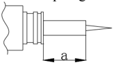
Systém riadenia obohacovania zmesi
| Položka | Popis |
|---|---|
| Dĺžka piesta počiatočného obohatenia *1 | 10.7~15.4mm |
| Odpor počiatočného obohatenia *2 | 17.7~18.7 Ω |
( *1 ) Údaje sú len orientačné. ( *2 ) Podmienka merania: dĺžka piesta počiatočného obohatenia =10.7mm Údaje sú len orientačné.
Uťahovací moment
Predpísaný uťahovací moment
| Uťahovaný diel | Uťahovaný diel | Názov dielu | Rozmer závitu | Počet | Uťahovací moment |
|---|---|---|---|---|---|
| Zapaľovacia sviečka | - | M12 | 1 | 17 Nm | |
| Zotrvačník | Matica | M20 | 1 | 150 Nm | |
| Montáž karburátora | Skrutka | M6 | 2 | 8 Nm | |
| Konzola karburátora | Skrutka | M6 | 3 | 8 Nm |
| 1. utiahnutie | Skrutka | M9 | 6 | 23Nm | |
|---|---|---|---|---|---|
| 2. utiahnutie | Skrutka | M9 | 6 | 46 Nm | |
| 1. utiahnutie | Skrutka | M6 | 3 | 6 Nm | |
| 2. utiahnutie | Skrutka | M9 | 6 | 12 Nm | |
| Olejový filter | Olejový filter | - | - | 1 | 18 Nm |
| Svorník olejového filtra | Svorník olejového filtra | - | - | 1 | 40 Nm |
| Poistná matica (vahadlo) | Poistná matica (vahadlo) | Matica | M6x0.75 | 4 | 14 Nm |
| Montáž motorovej jednotky | Montáž motorovej jednotky | Skrutka | M8 | 8 | 21 Nm |
| 1. utiahnutie | Skrutka | M6 | 7 | 6 Nm | |
| 2. utiahnutie | Skrutka | M6 | 7 | 12 Nm | |
| Kryt termostatu | Kryt termostatu | Skrutka | M6 | 2 | 7Nm |
| 1. utiahnutie | Skrutka | M8 | 6 | 15 Nm | |
| 2. utiahnutie | Skrutka | M8 | 6 | 30 Nm | |
| 1. utiahnutie | Skrutka | M6 | 6 | 6 Nm | |
| 2. utiahnutie | Skrutka | M6 | 6 | 12 Nm | |
| Ojnica | 1. utiahnutie | Skrutka | M6 | 4 | 6 Nm |
| Ojnica | 2. utiahnutie | Skrutka | M6 | 4 | 17 Nm |
| Hnaná remenica | Hnaná remenica | Skrutka | M10 | 1 | 38 Nm |
| Upevnenie spodnej jednotky | Upevnenie spodnej jednotky | Skrutka | M10 | 4 | 37 Nm |
| Kryt spodnej skrine | Kryt spodnej skrine | Skrutka | M6 | 2 | 11Nm |
| Vstup vody | Vstup vody | Skrutka | M5 | 2 | 4 Nm |
| Vypúšťacia skrutka oleja | Vypúšťacia skrutka oleja | Skrutka | - | 1 | 9 Nm |
| Kontrolný otvor oleja | Kontrolný otvor oleja | Skrutka | - | 1 | 9 Nm |
| Pastorok | Pastorok | Matica | M10 | 1 | 50 Nm |
| Matica lodnej skrutky | Matica lodnej skrutky | Matica | M14 | 1 | 34 Nm |
| Riadiaca rukoväť | Riadiaca rukoväť | Matica | M10 | 1 | 10 Nm |
| Riadiaca rukoväť | Riadiaca rukoväť | Samoistiaca matica | M10 | 1 | 22 Nm |
| Výfukové potrubie | Výfukové potrubie | Skrutka | M6 | 3 | 10 Nm |
| Plynová rukoväť | Plynová rukoväť | Skrutka | M5 | 1 | 3 Nm |
| Konzola radiacej páky | Konzola radiacej páky | Skrutka | M6 | 4 | 10 Nm |
| Listová pružina radenia | Listová pružina radenia | Skrutka | M6 | 1 | 10 Nm |
| Malý pásik spodného krytu | Malý pásik spodného krytu | Skrutka | M6 | 2 | 10 Nm |
| Upínacia konzola | Upínacia konzola | Samoistiaca matica | - | 2 | 45 Nm |
| Vypúšťacia skrutka oleja | Vypúšťacia skrutka oleja | Skrutka | M14 | 1 | 27 Nm |
| Uťahovaný diel | Názov dielu | Rozmer závitu | Počet | Uťahovací moment |
|---|---|---|---|---|
| Zapaľovacia cievka | Skrutka | M6 | 2 | 8 Nm |
| Zostava CDI | Skrutka | M6 | 2 | 5 Nm |
| Konzola zostavy CDI | Skrutka | M6 | 2 | 5 Nm |
| Cievka statora | Skrutka | M5 | 3 | 6 Nm |
| Impulzná cievka | Skrutka | M5 | 2 | 5 Nm |
Všeobecné uťahovacie momenty
| Matica (a) | Skrutka (b) | Uťahovací moment |
|---|---|---|
| 8mm | M5 | 5Nm |
| 10mm | M6 | 8 Nm |
| 12mm | M8 | 18 Nm |
| 14mm | M10 | 36 Nm |
| 17mm | M12 | 43 Nm |
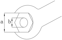
Pravidelný servis
Harmonogram údržby
| Položky | Obsah | Prvá údržba | Prvá údržba | Všeobecný interval údržby | Všeobecný interval údržby |
|---|---|---|---|---|---|
| 10 hodín (mesiac) | 50 hodín (3 mesiace) | 100 hodín (6 mesiacov) | 200 hodín (1 rok) | ||
| Anóda | Kontrola/výmena | ○ | ○ | ||
| Anóda (vnútorná) | Kontrola/výmena | ○ | |||
| Kanál chladiacej vody | Čistenie | ○ | ○ | ||
| Zapaľovacia sviečka | Čistenie/nastavenie/výmena | ○ | ○ | ||
| Mazacie miesta | Mazanie mazivom | ○ | |||
| Palivový filter | Kontrola/výmena | ○ | ○ | ○ | |
| Palivový systém | Kontrola | ○ | ○ | ○ | |
| Palivová nádrž | Kontrola/čistenie | ○ | |||
| Voľnobežné otáčky | Kontrola/nastavenie | ○ | ○ | ||
| Motorový olej | Výmena | ○ | ○ | ||
| Olejový filter | Výmena | ○ | |||
| Ventilová vôľa (OHC) | Kontrola/nastavenie | ○ | ○ | ||
| Predstih zapaľovania | Kontrola | ○ | ○ | ||
| Termostat | Kontrola | ○ | |||
| Prevodový olej | Výmena | ○ | ○ | ||
| Vodné čerpadlo | Kontrola | ○ |
| Vrtuľa a závlačka | Kontrola/výmena | ○ | ○ | |
|---|---|---|---|---|
| Rozvodový remeň | Kontrola/výmena | ○ | ○ | |
| Plynové lanko | Kontrola/nastavenie | ○ | ||
| Radiaca páka/radiace lanko | Kontrola/nastavenie | ○ |
UPOZORNENIE:
Po prevádzke prívesného motora v slanej, odpadovej alebo kalnej vode ho okamžite prepláchnite čistou sladkou vodou.
Ak často používate olovnatý benzín, kontrolujte ventil a súvisiace komponenty každých 100 hodín.
Rozvodový remeň sa musí meniť každých 1000 hodín (5 rokov).
Palivový systém
- SKONTROLUJTE PALIVOVÚ NÁDRŽ, KARBURÁTOR, PALIVOVÉ ČERPADLO A PALIVOVÉ POTRUBIE Skontrolujte, či nie sú poškodené alebo netesné. V prípade potreby ich vymeňte.
Skontrolujte, či palivový filter v nádrži nie je znečistený. V prípade potreby ho vyčistite alebo vymeňte.
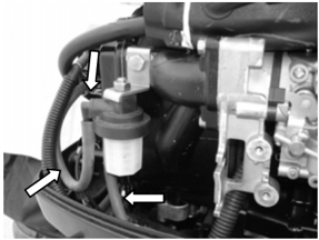
2. Skontrolujte palivový kohút a palivovú spojku
Skontrolujte, či palivový kohút a palivová spojka nie sú prasknuté, poškodené alebo netesné. V prípade potreby ich vymeňte.
3. Skontrolujte palivový filter
Skontrolujte, či palivový filter nie je prasknutý, poškodený alebo znečistený zvnútra. Ak áno, vymeňte ho.
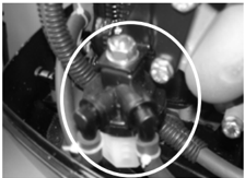
UPOZORNENIE:
Vyčistite rozliate palivo.
Motorová jednotka
Hladina motorového oleja
- Vyberte mierku oleja a skontrolujte, či je hladina motorového oleja medzi nasledujúcimi hornou a dolnou značkou.
- Ak je hladina nad hornou značkou, vypustite motorový olej; ak je pod dolnou značkou, doplňte motorový olej po hornú značku.
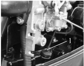
- Mierka oleja 2. Značka hornej hladiny 3. Značka dolnej hladiny

UPOZORNENIE:
Spustite motor a potom ho vypnite, počkajte niekoľko minút a znova skontrolujte hladinu motorového oleja mierkou.
Ak hladina motorového oleja stále nie je správna, podľa potreby olej doplňte alebo vypustite.
Výmena motorového oleja
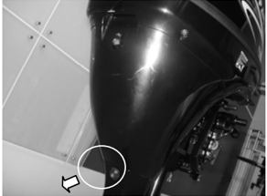
- Odstráňte zátku hladiny oleja, vypúšťaciu skrutku a jej tesnenie; vypustite motorový olej.
- Namontujte nové tesnenie skrutky; namontujte vypúšťaciu skrutku oleja.
- Nalejte motorový olej cez plniaci otvor. Množstvo motorového oleja: 1.7 L (pred výmenou olejového filtra) 1.9 L (po výmene olejového filtra ) Typ oleja: API: SE, SF, SG, SH, SJ alebo SAE: 10W30, 10W40
- Namontujte zátku kontroly hladiny oleja.
- Skontrolujte hladinu motorového oleja.
Ventilová vôľa
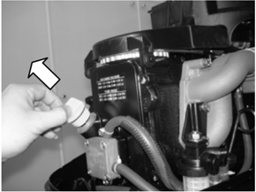
- Odstráňte núdzové vypínacie lanko z vypínača motora. Odstráňte koncovku zo zapaľovacej sviečky.
- Odstráňte štartér a kryt remeňa.
- Odstráňte palivové čerpadlo a veko valca.
- Skontrolujte, či rozvodový remeň nie je uvoľnený, zostarnutý alebo poškodený. V prípade potreby ho vymeňte.
- Otáčajte zotrvačníkom v smere hodinových ručičiek, aby sa značka "1" na hnanej remenici zarovnala so značkou """ na hlave valca.
Skontrolujte vôľu sacieho a výfukového ventilu horného valca. V prípade potreby ju nastavte.
- Otočte zotrvačník v smere hodinových ručičiek tak, aby sa značka '2' na hnanej remenici zarovnala so značkou '▼' na hlave valca.
Skontrolujte vôľu sacieho a výfukového ventilu dolného valca. V prípade potreby ju nastavte.
UPOZORNENIE:
Neotáčajte zotrvačníkom proti smeru hodinových ručičiek, pretože sa môže poškodiť ventilový mechanizmus.
Poznámka:
Ventilovú vôľu nastavujte pri studenom motore.
| Ventilová vôľa | Sací ventil | 0.15~0.25mm |
|---|---|---|
| (za studena) | Výfukový ventil | 0.25~0.35mm |
- Povoľte poistnú maticu a otáčaním nastavovacej skrutky dosiahnite predpísanú ventilovú vôľu.
Poznámka:
Otáčaním nastavovacej skrutky v smere hodinových ručičiek znížte ventilovú vôľu.
Otáčaním nastavovacej skrutky proti smeru hodinových ručičiek zvýšte ventilovú vôľu.
- Znovu namontujte diely.
Zadné ovládanie:
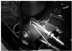
- Otočte plynovú rukoväť do úplne zatvorenej polohy.
- Skontrolujte, či lanko plynu nie je uvoľnené, či páka škrtiacej klapky dosadá na dorazovú skrutku alebo či
1
Zapaľovacia sviečka
- Odstráňte koncovku sviečky a zapaľovaciu sviečku.
- Odstráňte karbónové usadeniny z elektród.
- Skontrolujte, či elektródy nie sú skorodované alebo zanesené a či podložka nie je poškodená. V prípade potreby vymeňte zapaľovaciu sviečku. Typ sviečky: DPR7EA 9
- Skontrolujte, či je medzera elektród sviečky v rámci špecifikácie. V prípade potreby vymeňte sviečku.
- Namontujte sviečku. Kľúčom na sviečky ju utiahnite predpísaným momentom. Predpísaný moment: 17 Nm
Ovládací systém
Plynová rukoväť
doraz mechanizmu plynovej rukoväti dosadá na kontrolnú platničku na pevnej konzole.
Dorazová doska 2. Doraz

- Povoľte nastavovaciu skrutku lanka plynu, nastavte polohu lanka a utiahnite nastavovaciu skrutku.
- Dorazová skrutka plynového lanka
Predné ovládanie:
- Presuňte radiacu páku do neutrálnej polohy.
- Skontrolujte, či doraz mechanizmu plynu dosadá na dorazovú dosku držiaka.
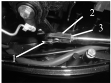
- Povoľte poistnú maticu, vyberte závlačku a potom odpojte prípojku lanka.
- Nastavte polohu prípojky tak, aby sa jej otvor zarovnal s čapom mechanizmu plynu.
- Závlačka 2. Prípojka lanka 3. Poistná matica
UPOZORNENIE:
Prípojka lanka musí byť zaskrutkovaná viac než 8mm.
- Namontujte závlačku a utiahnite poistnú maticu.
Radenie
Zadné ovládanie:
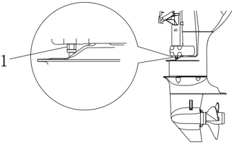
Pri radení z neutrálu na chod vpred alebo spätný chod skontrolujte plynulosť radenia. V prípade potreby nastavte valcovú maticu.
Predné ovládanie:
- Pri radení z neutrálu na chod vpred alebo spätný chod skontrolujte plynulosť radenia. V prípade potreby nastavte dĺžku radiaceho lanka.
- Nastavte radiacu páku na ovládacej skrinke do neutrálu.
Poznámka:
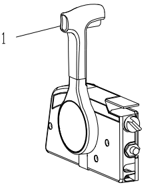
Keď je radiaca páka v neutráli, skontrolujte, či je kolmá na montážnu plochu motora.
Voľnobežné otáčky
Skontrolujte voľnobežné otáčky a v prípade potreby ich nastavte.
- Motor zahrievajte 5 minút.
- Pripojte otáčkomer ku káblu sviečky a zmerajte voľnobežné otáčky v RPM. Ak sú mimo špecifikácie, nastavte ich.
- Valcová matica
Voľnobežné otáčky
925~1025 r/min
- Radiaca páka
1
- Otáčajte dorazovou skrutkou plynu v smere alebo proti smeru hodinových ručičiek, kým nedosiahnete predpísané voľnobežné otáčky.
Poznámka:
Otáčaním v smere hodinových ručičiek zvýšte voľnobežné otáčky, otáčaním proti smeru ich znížte. V prípade potreby otáčajte skrutkou voľnobehu na karburátore v jednom alebo druhom smere, kým nedosiahnete predpísané otáčky.
UPOZORNENIE:
Pred nastavením voľnobehu musí byť lanko plynu správne nastavené. Po nastavení voľnobehu môžete v prípade potreby lanko znovu nastaviť.
Ochrana proti štartovaniu so zaradenou rýchlosťou
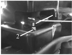
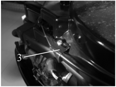
Nastavte radiacu páku do neutrálu a skontrolujte, či sa značka ' ▋' na blokovacej západke zarovnáva so značkou ' ▼ ' na skrini štartéra. V prípade potreby nastavte montážnu platničku blokovacieho lanka, aby sa značky zarovnali.
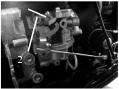
- Dorazová skrutka škrtiacej klapky
- Skrutka voľnobehu
- Značka ' ▋ ' 2. Značka ' ▼ ' 3. Montážna platnička blokovacieho lanka
Spodná jednotka
Prevodový olej
Kontrola hladiny prevodového oleja
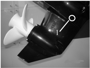
Vyberte skrutku kontrolnej zátky oleja. Ak prevodový olej vyteká, hladina je správna; inak doplňte prevodový olej.
- Skrutka kontrolnej zátky oleja
Výmena prevodového oleja
- Držte prívesný motor vo zvislej polohe.
- Pod prívesný motor umiestnite nádobu s dostatočným objemom.
- Odstráňte vypúšťaciu skrutku oleja a skrutku zátky hladiny oleja a potom vypustite prevodový olej..
- Doplňte prevodový olej cez otvor vypúšťacej skrutky pomocou tlakového plniaceho zariadenia.
- Keď prevodový olej vyteká cez otvor kontrolnej zátky, namontujte jej skrutku.
- Kontrolná skrutka hladiny oleja 2. Vypúšťacia skrutka oleja
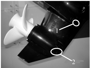
- Namontujte vypúšťaciu skrutku a potom odstráňte vytečený prevodový olej.
Poznámka:
Skontrolujte vypustený prevodový olej. Ak je mliečny, skontrolujte olejové tesnenie a v prípade potreby ho vymeňte. _ Ak olej obsahuje kovové triesky, skontrolujte ozubené kolesá a ložisko.
UPOZORNENIE:
Tesnenie vypúšťacej skrutky oleja sa musí vždy vymeniť.
Kontrola netesnosti spodnej jednotky
Pripojte tester netesností k otvoru zátky hladiny oleja a skontrolujte tesnosť spodnej jednotky. Ak tlak klesne (tlak: 1kg/cm³), skontrolujte olejové tesnenie a komponenty.
Všeobecná kontrola
Anóda
Skontrolujte anódu spodnej jednotky a motorovú anódu (na kryte termostatu). Odstráňte mastné nečistoty a usadeniny. Ak opotrebenie alebo poškodenie presahuje 1/2, anódu vymeňte.
UPOZORNENIE:
Anódu nemažte mazivom ani nenatierajte, inak nebude správne fungovať.
Mazacie miesta
- Riaďte sa obrázkom mazacích miest a naneste vodoodolné mazivo.
- Na hriadeľ vrtule naneste antikorózne mazivo.
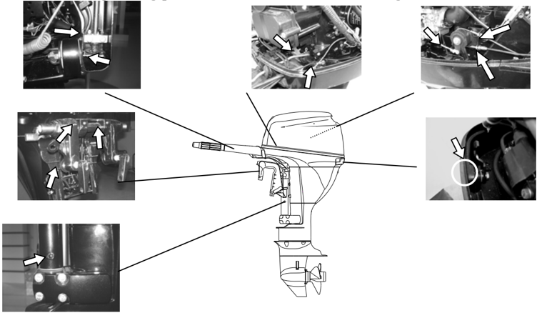

.
Kanál chladiacej vody
- Skontrolujte kanál chladiacej vody. Ak je upchatý, vyčistite ho.
- Vstup kanála chladiacej vody
- Vložte prívesný motor do vody a uistite sa, že hladina vody je nad doskou proti víreniu. Potom naštartujte motor.
- Skontrolujte, či voda vyteká z kontrolného otvoru chladiacej vody. Ak voda netečie alebo tečie prerušovane, skontrolujte kanál chladiacej vody.
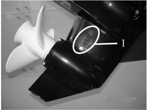

- Vstup chladiacej vody 2. Kontrolný otvor chladiacej vody
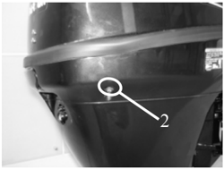
Termostat
- Odstráňte veko termostatu a termostat.
- Zaveste termostat do nádoby s vodou.
- Zohrejte nádobu.
- Skontrolujte výšku otvorenia ventilu pri predpísaných teplotách vody. Ak nezodpovedá špecifikácii, vymeňte ho.
- Namontujte termostat a jeho veko, potom utiahnite skrutky podľa špecifikácie.
| Teplota vody | Výška otvorenia ventilu |
|---|---|
| 58 ~ 62℃ | 0.05mm |
| Nad 70℃ | Viac ako 3mm |
Vrtuľa
Skontrolujte, či listy lodnej skrutky a vnútorné drážkovanie nie sú prasknuté, poškodené alebo opotrebované. V prípade potreby ju vymeňte.
Ručný štartér
POZNÁMKA:
Pri servise vždy používajte ochranné okuliare a rukavice. Aby ste zabránili náhodnému naštartovaniu motora, odpojte koncovku sviečky a bezpečnostné lanko zo zostavy vypínača motora.
Rozložený výkres
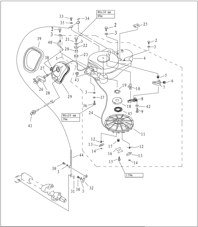
| Číslo dielu | Popis | Popis | Poznámky | ||
|---|---|---|---|---|---|
| 1 | F25-05160000 | Zostava štartéra | 1 | ||
| 2 | GB/T5783-M6x25 | M6x25 | SKRUTKA M6x25 | 4 | |
| 3 | ;GB/T97.1-6 | 6 | PLOCHÁ PODLOŽKA 6 | 9 | |
| 4 | F25-05160100 | TELESO ŠTARTÉRA | 1 | ||
| 5 | F25-05160003 | Pružina blokovacieho mechanizmu | 1 | ||
| 6 | F25-05160005 | Ťažná pružina | 1 | ||
| 7 | F25-05160001 | Blokovací mechanizmus | 1 | ||
| 8 | F25-05160006 | PEVNÁ ZÁPADKA | 1 | ||
| 9 | GB/T5285-ST4.8x26 | SAMOREZNÁ SKRUTKA ST4.8x26 | 3 | ||
| 10 | F25-05160004 | BLOKOVACIA ZÁPADKA | 1 | ||
| 11 | F25-05160301 | Štartovacie koleso | 1 | ||
| 12 | F25-05160304 | PRUŽINA HNACEJ ZÁPADKY | 2 | ||
| 13 | F25-05160305 | HNACIA ZÁPADKA | 2 | ||
| 14 | GB/T896-6 | 6 | POISTNÝ KRÚŽOK 6 | 2 | |
| 15 | F25-05160018 | SKRUTKA HNACEJ PLATNIČKY | 1 |
| Číslo dielu | Popis | Poznámky | ||
|---|---|---|---|---|
| 16 | F25-05160017 | HNACIA PLATNIČKA | ||
| 17 | F25-05160016 | Pružina hnacej dosky | ||
| 18 | F25-05160014 | PRUŽINA SEDLA | ||
| 19 | F25-05160013 | SEDLO TLMIACEJ PRUŽINY | ||
| 20 | F25-05160009 | OS REMENICE | ||
| 21 | GB/T5783-M6x30 | M6x30 | SKRUTKA M6x30 | |
| 22 | GB/T5287-6 | 6 | VEĽKÁ PODLOŽKA 6 | |
| 23 | F25-05160008 | ŠTARTOVACIA REMENICA | ||
| 24 | F25-05160019 | φ5x1.68 | ŠTARTÉR | |
| 25 | F25-05160012 | GUMOVÝ NÁVLEK | ||
| 26 | F4-04130102 | Kryt | ||
| 27 | F25-05160021 | TLMIČ | ||
| 28 | F25-05160501 | Štartovacia rukoväť | ||
| 29 | F25-05160401 | Rám štartéra | ||
| 30 | GB/T5783-M6x10 | M6x10 | SKRUTKA M6x10 | |
| 31 | F15-00000012 | φ1.8 | PRUŽINA | |
| 32 | F25-05000028 | ZOSTAVA DRŽIAKA LANKA | ||
| 33 | GB/T5783-M5x12 | M5x12 | SKRUTKA M5x12 | |
| 34 | F25-05160002 | φ1 | PRUŽINA | |
| 35 | GB/T96-5 | 5 | VEĽKÁ PODLOŽKA 5 |
| Číslo dielu | Popis | Poznámky | ||
|---|---|---|---|---|
| 36 | GB/T5783-M6x20 M6x20 | SKRUTKA M6x20 | 2 | |
| 37 | GB/T93-6 6 | Pružná podložka 6 | 2 | |
| 38 | HT 2.5x60 60x2.5 | SPONA 2.5x60 | 1 | |
| 39 | F25-05160402 | Tesnenie z penovej gumy | 1 | |
| 40 | F25-05160403 | UVOĽŇOVACÍ KOLÍK | 1 | |
| 41 | F15-07130303 | KONTROLKA OLEJOVEJ VANE | 1 | |
| 42 | A5 GB/T848-5 | MALÁ PODLOŽKA 5 | 3 | |
| 43 | GB/T889.1-M6 M6 | POISTNÁ MATICA | 2 | |
| 44 | F25-05160200 | ZOSTAVA LANKA BLOKOVANIA ŠTARTÉRA | 1 | |
| 45 | F25-05160015 | ŠPIRÁLOVÁ PRUŽINA | 1 |
Demontáž
- Otvorte horný kryt motora.
- Odpojte lanko od blokovacieho mechanizmu.
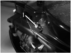
Nastavovacia matica
- Odstráňte upevňovacie skrutky štartéra a vyberte štartér.
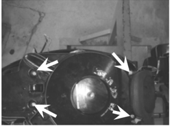
Výmena štartovacieho lanka
- Vytiahnite štartovacie lanko a vložte ho do zárezu štartovacieho kolesa. Otáčajte kolesom v smere hodinových ručičiek, kým sa špirálová pružina neuvoľní.
- Úplne vytiahnite štartovacie lanko.
- Odstráňte kryt štartovacej rukoväti a odstráňte štartovacie lanko. Rozviažte uzol na jeho konci.
- Úplne vytiahnite lanko zo štartovacieho kolesa.
- Vložte nové lanko do štartéra a upevnite ho na štartovacie koleso a rukoväť štartéra. Na konci lanka uviažte uzol podľa obrázka.
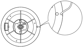
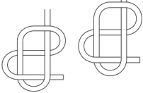
- Vložte lanko do zárezu štartovacieho kolesa a niekoľkokrát otočte kolesom proti smeru hodinových ručičiek.
- Viackrát potiahnite štartovaciu rukoväť a skontrolujte, či sa štartovacie koleso otáča plynulo a či lanko nie je uvoľnené. V prípade potreby zopakujte kroky 6 a 7.
Demontáž a kontrola
- Odstráňte štartovacie lanko a zostavu rámu štartéra.
- Odstráňte pevnú platničku západky. Odstráňte blokovací mechanizmus a blokovaciu západku.
- Odstráňte skrutku hnacej platničky. Odstráňte hnaciu platničku, jej pružinu a hnaciu západku.
- Odstráňte štartovacie koleso, sedlo špirálovej pružiny a jeho tlmiacu podložku.
VAROVANIE: Štartovacie koleso demontujte opatrne, aby špirálová pružina nevyskočila a nespôsobila zranenie.
- Odstráňte špirálovú pružinu.
- Skontrolujte, či blokovací mechanizmus a západka nie sú prasknuté, opotrebované alebo poškodené. V prípade potreby ich vymeňte.
- Skontrolujte praskliny, opotrebovanie alebo poškodenie hnacej západky. V prípade potreby ju vymeňte.
- Skontrolujte, či pružina západky nie je prasknutá, zdeformovaná alebo poškodená. V prípade potreby ju vymeňte.
- Skontrolujte, či špirálová pružina a jej sedlo nie sú zlomené, zdeformované alebo poškodené. V prípade potreby ich vymeňte.


Montáž
Postupujte v opačnom poradí demontáže štartéra.
Inštalácia
- Položte štartér na motorovú jednotku.
- Zaskrutkujte šesťhrannú skrutku a utiahnite ju predpísaným momentom.
- Namontujte lanko blokovacieho mechanizmu.
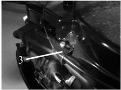
- Nastavte pevnú platničku blokovacieho lanka a zarovnajte značku blokovacej západky so značkou skrine štartéra.
- Značka ' ▋ ' 2. Značka ' ▼ ' 3. Pevná platnička blokovacieho lanka

Zapaľovací systém
POZNÁMKA:
Pri kontrole a opravách zapaľovacieho systému držte ruky, odev, vlasy a osobné predmety mimo dosahu rotujúceho zotrvačníka.
.
Zapaľovaciu cievku kontrolujte na izolovanom pracovnom stole, aby ste zabránili úniku elektrického prúdu a úrazu elektrickým prúdom.
Počas chodu motora sa nedotýkajte zapaľovacej cievky ani sviečky, aby ste predišli úrazu elektrickým prúdom. Vodiče držte mimo dosahu rotujúceho zotrvačníka, aby nedošlo k ich prerezaniu alebo opotrebeniu izolácie.
Pri výmene upevňovacích dielov, ako sú matice a skrutky, používajte iba diely pôvodného výrobcu alebo diely z rovnakého materiálu a s rovnakou pevnosťou. Diely musia byť utiahnuté predpísanými momentmi.
Rozložený výkres
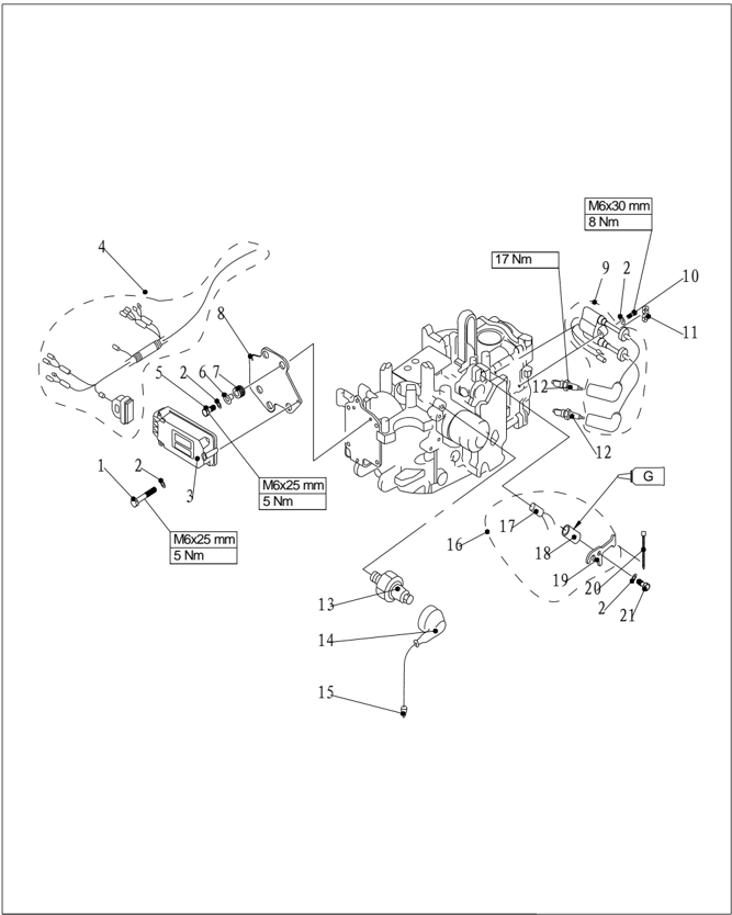
| Číslo dielu | Popis | Poznámky | ||
|---|---|---|---|---|
| 1 | GB/T6563-M6x45 | POISTNÁ SKRUTKA M6x45 M6x45 | 3 | |
| 2 | GB/T97.1-6 | PODLOŽKA 6 6 | 8 | |
| 3 | F25-05090001 | ZOSTAVA JEDNOTKY C.D.I. | 1 | |
| 4 | F25-05090002 | ZOSTAVA KABELÁŽE C.D.I. | 1 | |
| 5 | GB/T5783-M6x25 | SKRUTKA M6x45 M6x25 | 3 | |
| 6 | F25-05090005 | PUZDRO ZAPAĽOVANIA | 3 | |
| 7 | F25-05090004 | TLMIACE PUZDRO | 3 |

| Číslo dielu | Popis | Popis | Poznámky | ||
|---|---|---|---|---|---|
| 11 | F25-05000016 | NYLONOVÁ SPONA | 1 | ||
| 12 | DPR7EA 9 NGK | Zapaľovacia sviečka | 2 | ||
| 13 | F15-07010103 | SNÍMAČ TLAKU OLEJA | 1 | ||
| 14 | F15-07010101 | IZOLAČNÝ NÁVLEK | 1 | ||
| 15 | F15-07010102 | ZOSTAVA PRÍVODNÉHO VODIČA | 1 | ||
| 16 | F25-05010200 | ZOSTAVA REGULÁTORA TEPLOTY | 1 | ||
| 17 | F25-05010201 | REGULÁTOR TEPLOTY | 1 | ||
| 18 | F25-05010202 | PUZDRO REGULÁTORA TEPLOTY | 1 | ||
| 19 | F25-05010203 | PLATNIČKA REGULÁTORA TEPLOTY | 1 | ||
| 20 | HT-25x60 | NYLONOVÁ PÁSKA 25x60 | 1 | ||
| 21 | GB/T5783-M6x12 | M6x12 | SKRUTKA M6x12 | 1 |

| Číslo dielu | Popis | Popis | Poznámky | |
|---|---|---|---|---|
| 1 | GB/T70.1-M8x12 | M8x12 | SKRUTKA M8x12 | |
| 2 | F25-05000027 | ŠTARTOVACÍ HRIADEĽ | ||
| 3 | F25-05000026 | Matica zotrvačníka | ||
| 4 | F25-05000025 | |||
| 5 | F25-05150000 | ZOSTAVA ZOTRVAČNÍKA | ||
| F25-05150000W | ZOSTAVA ZOTRVAČNÍKA | Typ s elektrickým štartovaním | ||
| 6 | GB/T70.1-M5x25 | M5x25 | SKRUTKA M5x25 | |
| 7 | F25-05140000 | ZOSTAVA STATORA | ||
| 8 | F25-05000034 | Φ8x90 | VLNITÝ NÁVLEK | |
| 9 | GB/T5783-M5x16 | M5x16 | SKRUTKA M5x16 | |
| 10 | GB/T97.1-5 | 5 | Plochá podložka 5 | |
| 11 | F25-05110000 | Impulzná cievka | ||
| 12 | F25-05000024 | |||
| 13 | F25-05110001 | IZOLOVANÝ KONEKTOR |
Elektrické štartovanie
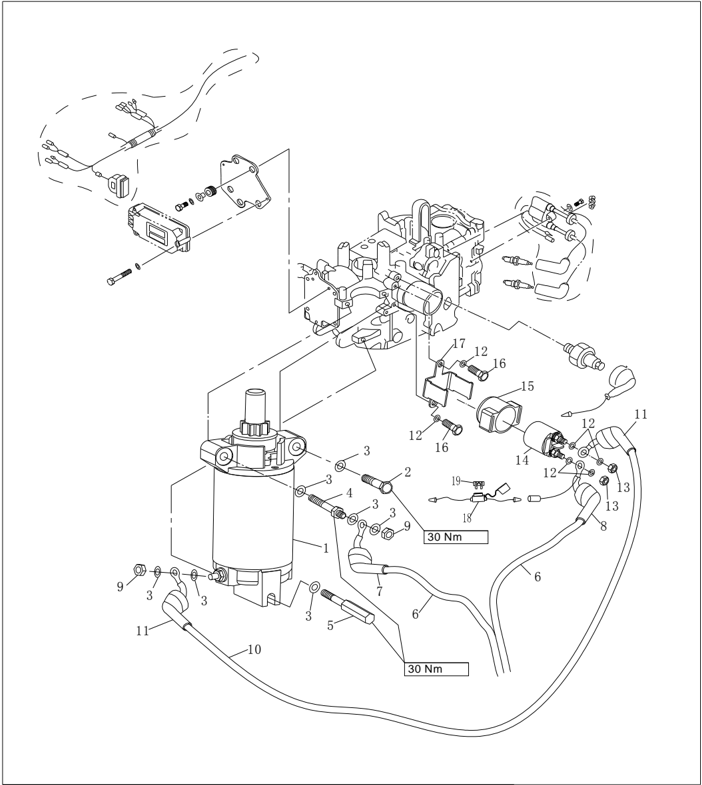
| Číslo dielu | Popis | Poznámky | ||
|---|---|---|---|---|
| F25-05170100W | ŠTARTOVACÍ MOTOR | 1 | ||
| M8×50 | 1 | |||
| GB/T97.1-85 | 8 | PODLOŽKA 8 | 7 | |
| F25-05170001W | M8 | 1 | ||
| F15-07150002W | M8 | 1 | ||
| F15-07150200W | 1 | |||
| F25-05170201W | A | 1 | ||
| F25-05170202W | B | 1 | ||
| GB/T6170-M8 | M8 | 2 | ||
| F25-05170400W | 1 | |||
| F25-05170401W | 2 | |||
| GB/T97.1-6 | 6 | PODLOŽKA 6 | 6 | |
| GB/T6170-M6 | M6 | 2 | ||
| F15-07150300W | RELÉ | 1 | ||
| F25-07150301W | NÁVLEK RELÉ | 1 | ||
| M6×12 | 2 | |||
| F25-07150302W | PLATNIČKA RELÉ | 1 | ||
| F25-05090100W | ZOSTAVA POISTKY | 1 | ||
| F15-07150001W | 20A | Poistka | 1 |
- 1 CDI
Schéma zapojenia
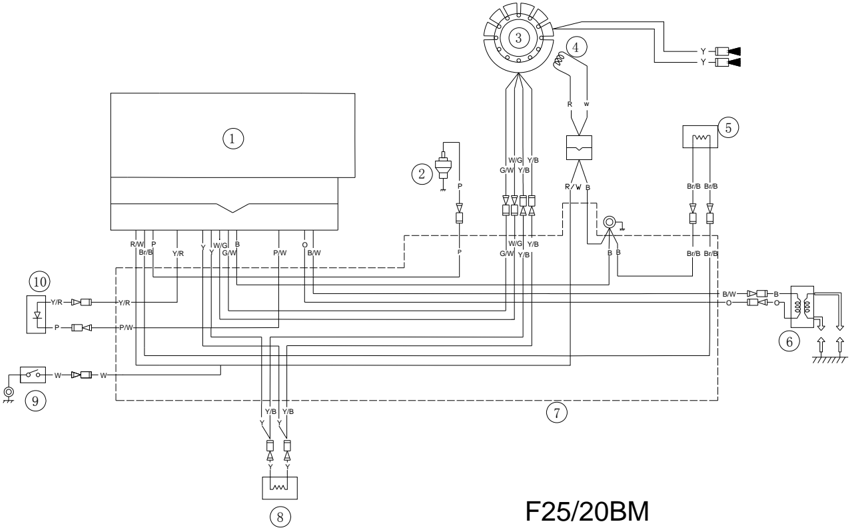
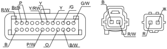
- 4 Impulzná cievka
○
- 3 Cievka statora
- 2 Snímač tlaku oleja
- 7 Zostava kabeláže CDI
- 6 Zapaľovacia cievka
Farby vodičov káblového zväzku:
| W | Biela | P | Ružová | W/B | Biela/Čierna |
|---|---|---|---|---|---|
| B | Čierna | G/W | Zelená/Biela | P/W | Ružová/Biela |
| R | Červená | Y/B | Žltá/Čierna | Br/B | Hnedá/Čierna |
| Y | Žltá | Y/R | Žltá/červená | W/G | Biela/Zelená |
| O | Oranžová | R/W | Červená/biela |
- 10 Kontrolka alarmu tlaku oleja
- 9 Spínač zastavenia motora
- 5 Termostat
- 8 Ventil počiatočného obohatenia zmesi
Elektrické štartovanie
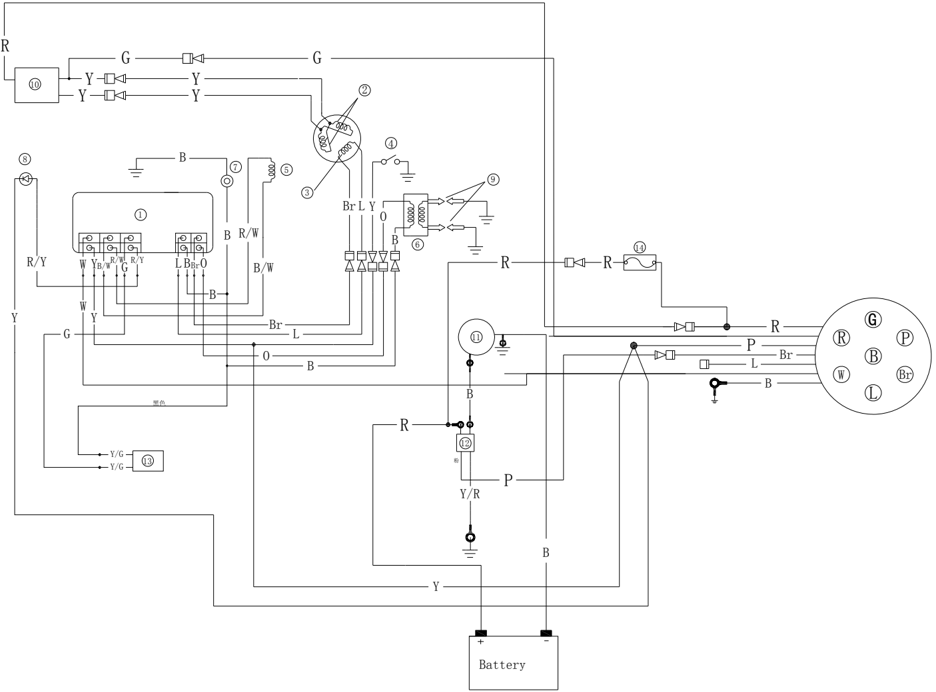
F25/20FW
- 4 Snímač tlaku oleja
- 5 Impulzná cievka
- 6 Zapaľovacia cievka
- 1 C D I
- 2 Nabíjacia cievka
- 3 Osvetľovacia cievka
Farby vodičov káblového zväzku:
| W | Biela | L | Modrá |
|---|---|---|---|
| B | Čierna | G | Zelená |
| R | Červená | Br | Hnedá |
| Y | Žltá | Y/R | Žltá/červená |
| O | Oranžová | R/W | Červená/biela |
Iskra zapaľovacej sviečky
- Odstráňte koncovku zo zapaľovacej sviečky. .
- 7 Spínač zastavenia motora
- 8 Kontrolka alarmu tlaku oleja
- 9 Zapaľovacia sviečka
- 10 Zostava usmerňovača
- 11 Štartovací motor
- 12 Štartovacie relé
- 13 Ventil počiatočného obohatenia zmesi
- 14 Poistka
- Pripojte tester zapaľovania ku koncovke sviečky.
- Naštartujte motor a sledujte iskry cez vybíjacie okienko skúšačky.
VAROVANIE:
Nedotýkajte sa žiadneho spoja vodiča skúšačky. Nepribližujte sa k horľavým plynom ani kvapalinám, aby ste zabránili nehodám spôsobeným zapálením iskrou.
Koncovka sviečky
- Odstráňte koncovku sviečky a skontrolujte, či nie je zlomená. V prípade potreby ju vymeňte.
- Namontujte koncovku sviečky. Otáčajte ju v smere hodinových ručičiek, kým pevne nedosadne.
Údržba zotrvačníka
- Pomocou držiaka zotrvačníka odstráňte maticu a puzdro štartéra; pomocou sťahováka zotrvačníka odstráňte zotrvačník.
- Skontrolujte, či je zotrvačník poškodený a či je časť s permanentným magnetom pevná. V prípade potreby ho vymeňte.

Kontrola CDI
Špičkové napätie CDI
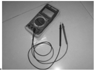
Na meranie špičkového napätia CDI použite digitálny tester obvodov a adaptér špičkového napätia.
Ak je napätie nižšie než predpísaná hodnota, skontrolujte prívodný vodič a zmerajte impulzy a špičkové výstupné napätie nabíjacej cievky.
.
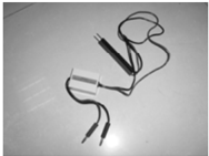
Digitálny tester obvodov Adaptér špičkového napätia
| Špičkové výstupné napätie CDI | Štartovanie (so záťažou) | 264V |
|---|---|---|
| Špičkové výstupné napätie CDI | 1500 r/min | 265V |
| Špičkové výstupné napätie CDI | 3500 r/min | 270V |
Poznámka:
Ak impulz a špičkové výstupné napätie nabíjacej cievky dosahujú alebo prekračujú predpísané hodnoty a špičkové výstupné napätie CDI je nižšie než predpísaná hodnota, vymeňte CDI.
- Špičkové napätie impulznej cievky
Pomocou digitálneho multimetra a adaptéra špičkového napätia zmerajte špičkové napätie. Ak je nižšie než predpísaná hodnota, skontrolujte odpor impulznej cievky.
Digitálny tester obvodov Adaptér špičkového napätia
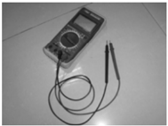
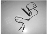
Špičkové napätie impulznej cievky
- Odpor impulznej cievky
Zmerajte odpor impulznej cievky. Ak nezodpovedá špecifikácii, vymeňte ju.
Odpor*
300~350Ω (
Pól (+) testera: červený/biely vodič; pól (-) testera: čierny vodič)
Poznámka:
Údaje sú len orientačné.
- Špičkové napätie nabíjacej cievky
Pomocou digitálneho multimetra a adaptéra špičkového napätia zmerajte špičkové napätie. Ak je nižšie než predpísaná hodnota, skontrolujte odpor nabíjacej cievky.
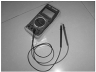
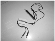
Digitálny tester obvodov Adaptér špičkového napätia
| Štartovanie (bez záťaže) | 12V |
|---|---|
| Štartovanie (so záťažou) | 12V |
| 1500 r/min (so záťažou) | 12V |
| 3500 r/min (so záťažou) | 12.4V |
Kontrola zapaľovacej cievky
- Odstráňte zapaľovaciu cievku a koncovku sviečky.
- Zmerajte odpor zapaľovacej cievky. Ak nezodpovedá špecifikácii, vymeňte ju.
Odpor: 0.08
~ 0.11 Ω (pól (+) testera: oranžový vodič; pól (-) testera: čierny vodič)
3.4 ~ 4.7k Ω
(Pól (+) skúšačky: oranžový vodič; pól (-): vysokonapäťový vodič)
Kontrola impulznej cievky
Kontrola nabíjacej cievky
| Špičkové napätie nabíjacej cievky | Štartovanie (bez záťaže) | 294V |
|---|---|---|
| Špičkové napätie nabíjacej cievky | Štartovanie (so záťažou) | 291V |
| Špičkové napätie nabíjacej cievky | 1500 r/min (so záťažou) | 291V |
| Špičkové napätie nabíjacej cievky | 3500 r/min (so záťažou) | 294V |
2. Odpor nabíjacej cievky
Zmerajte odpor nabíjacej cievky. Ak nezodpovedá špecifikácii, vymeňte ju.
Odpor: 660~710Ω (pól (+) testera: hnedý vodič; pól (-) testera: modrý vodič)
Palivový systém (podrobne)
POZNÁMKA:
Benzín je horľavá a veľmi prchavá kvapalina. Jeho únik môže spôsobiť požiar a výbuch. Motor neštartujte, kým nie sú všetky spoje palivového systému pripojené alebo namontované. Po dokončení všetkých krokov údržby krátkodobo natlakujte palivový systém a skontrolujte netesnosti.
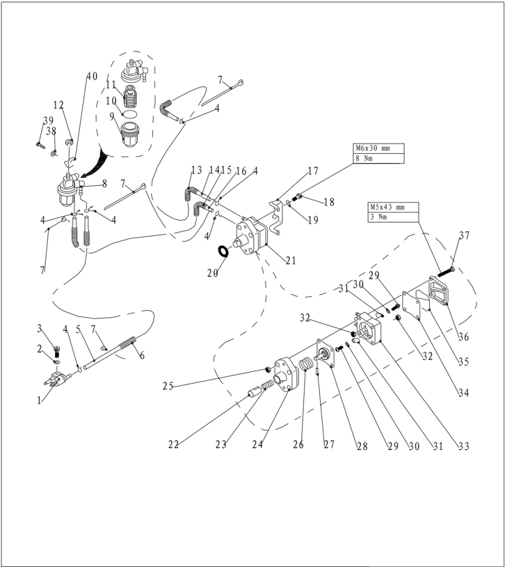
Rozložený výkres
| Číslo dielu | Popis | Popis | Poznámky | ||
|---|---|---|---|---|---|
| 1 | F4-05000200 | Zostava prípojky palivovej hadice | 1 | ||
| 2 | GB/T97.1-6 | 6 | PODLOŽKA 6 | 1 | |
| 3 | GB/T5783-M6x25 | M6×25 | Skrutka M6×25 | 1 | |
| 4 | F4-04000030 | B | 5 | ||
| 5 | F25-03000012 | A | Palivová hadica "A" | 1 | Φ10xΦ5x550 |
| 6 | F25-03000004 | VLNITÁ RÚRKA | 1 | Φ12x120 | |
| 7 | HT-2.5×60 | 2.5×60 | SPONA 2.5×60 | 6 | |
| 8 | F15-07080000 | Zostava filtra | 1 | ||
| 9 | F15-07080002 | Nádobka filtra | 1 | ||
| 10 | 1 | ||||
| 11 | F15-07080001 | Filtračná vložka | 1 | ||
| 12 | GB/T6170-M8 | M8 | MATICA M8 | 1 |
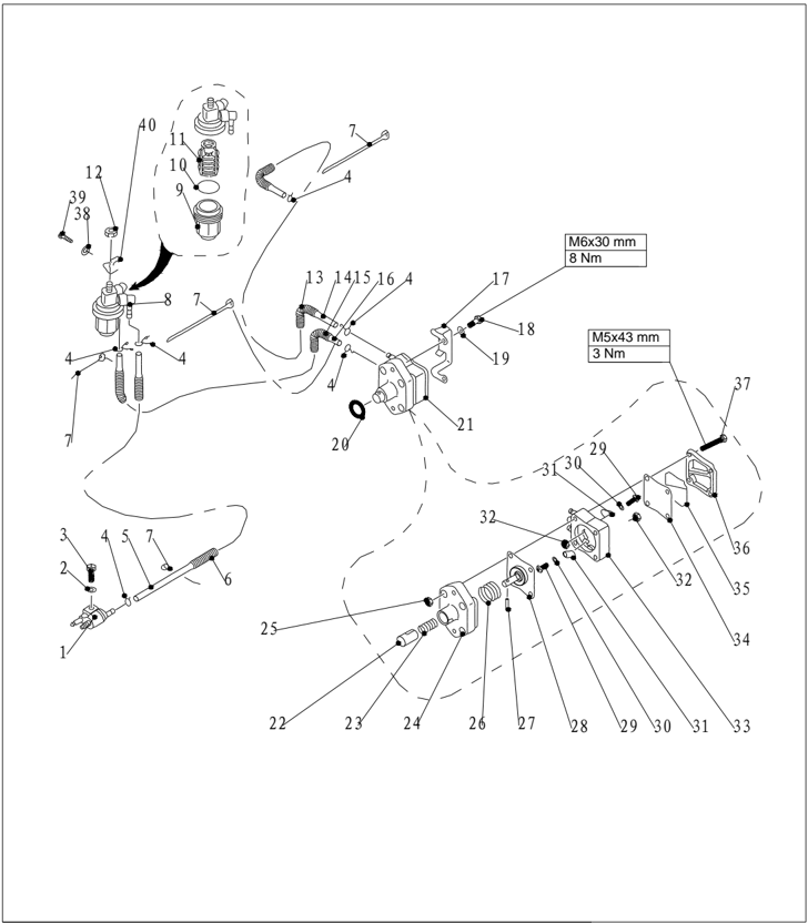
| Číslo dielu | Popis | Popis | Poznámky | ||
|---|---|---|---|---|---|
| 13 | F25-05000029 | VLNITÁ RÚRKA | 1 | Φ12x300 | |
| 14 | F25-05000012 | PALIVOVÁ RÚRKA | 1 | Φ10xΦ5x350 | |
| 15 | F25-05000033 | VLNITÁ RÚRKA | 1 | Φ12x120 | |
| 16 | F25-05000032 | () | HADICA | 1 | |
| 17 | F25-05000018 | 1 | |||
| 18 | GB/T5783-M6x30 | M6x30 | SKRUTKA M6x30 | 2 | |
| 19 | GB/T97.1-6 | 6 | PODLOŽKA 6 | 2 | |
| 20 | O-KRÚŽOK 24.7 x3.1 | 1 | |||
| 21 | F25-05130000 | Zostava palivového čerpadla | 1 | ||
| 22 | F25-05130004 | Piestik | 1 | ||
| 23 | F25-05130003 | Pružina piestika | 1 | ||
| 24 | F25-05130001 | Základňa palivového čerpadla | 1 | ||
| 25 | GB/T6170- M5 | M5 | MATICA M5 | 4 | |
| 26 | F25-05130002 | 1 | |||
| 27 | GB/T309-3x16.5 | Φ3x16.5 | 1 | ||
| 28 | F25-05130100 | Zostava membrány | 1 | ||
| 29 | F4-04090011 | M3x5 | 2 |
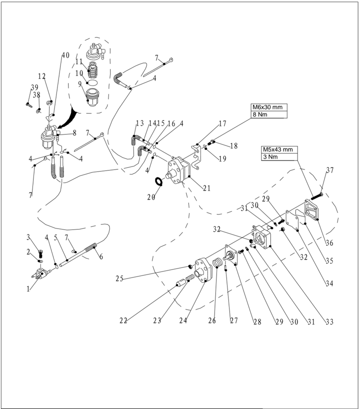
| Číslo dielu | Popis | Poznámky | |||
|---|---|---|---|---|---|
| 30 | GB/T848-3 | 3 | MALÁ PODLOŽKA 3 | 2 | |
| 31 | F4-04090005 | Doska | 2 | ||
| 32 | GB/T6170-M3 | M3 | MATICA 3 | 2 | |
| 33 | F25-05130201 | Teleso palivového čerpadla | 1 | ||
| 34 | F25-05130005 | Horná membrána | 1 | ||
| 35 | F25-05130006 | TESNENIE PALIVOVÉHO ČERPADLA | 1 | ||
| 36 | F25-05130007 | Kryt palivového čerpadla | 1 | ||
| 37 | GB/T818-M5x45 | 4 | |||
| 38 | GB/T97.1-8 | 8 | PODLOŽKA 8 | 1 | |
| 39 | GB/T5783-M8x14 | M8×14 | Skrutka M8×14 | 1 | |
| 40 | F25-05000017 | 1 |
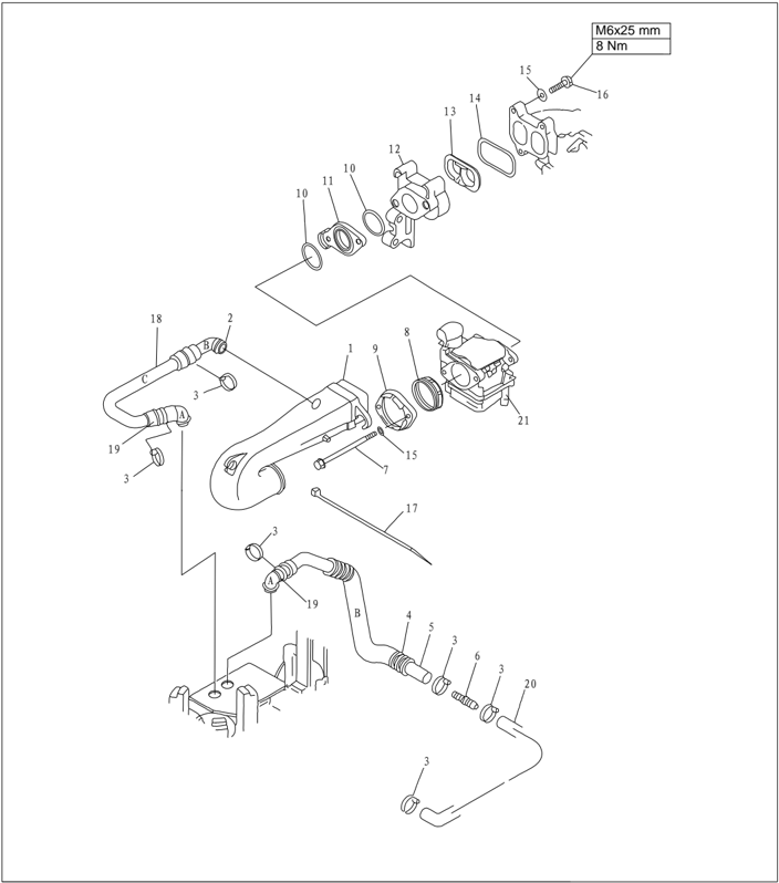
| Číslo dielu | Popis | Popis | Poznámky | ||
|---|---|---|---|---|---|
| 1 | F25-05080100 | 1 | |||
| 2 | F25-05080009 | B | ZOSTAVA ODVZDUŠŇOVAČA | 1 | |
| 3 | HT-3.6x150 | SPONA | 6 | ||
| 4 | F25-05000031 | φ20x250 | HADICA | 1 | |
| 5 | F25-05080006 | B | HADICA | 1 | |
| 6 | F25-02000018 | A | Spojovacia rúrka | 1 | |
| 7 | GB/T5782-M6x100 | M6X100 | 2 | ||
| 8 | F25-05080004 | GUMOVÉ TESNENIE | 1 | ||
| 9 | F25-05080005 | PRÍRUBA | 1 | ||
| 10 | F25-05000011 | 0 | O-krúžok | 2 | |
| 11 | F25-05000009 | IZOLÁTOR | 1 | ||
| 12 | F25-05060001 | POTRUBIE | 1 | ||
| 13 | F25-05060002 | VLOŽKA | 1 | ||
| 14 | F25-05060003 | Tesnenie potrubia | 1 | ||
| 15 | GB/T97.1-6 | 6 | PODLOŽKA 6 | 5 | |
| 16 | GB/T5783-M6x25 | M6X25 | 3 | ||
| 17 | HT-3.6x250 | 3.6x250 | SPONA 3.6x250 | 1 | |
| 18 | F25-05080008 | C | HADICA | 1 | |
| 19 | F25-05080007 | A | ZOSTAVA ODVZDUŠŇOVAČA | 2 | |
| 20 | F25-02000017 | A | HADICA | 1 | |
| 21 | F25-05070000 | ZOSTAVA KARBURÁTORA | 1 |
Nastavenie spojovacej tyče škrtiacej klapky
- Presuňte mechanizmus plynu do úplne otvorenej polohy. Presuňte tyč škrtiacej klapky karburátora do úplne otvorenej polohy.
- Mechanizmus plynu
- Tyč škrtiacej klapky karburátora
- Poistná skrutka
- V úplne otvorenej polohe utiahnite poistnú skrutku tyče plynu.
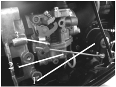
Demontáž a kontrola palivovej prípojky
- Odstráňte skrutky upevňujúce palivovú prípojku.
- Odstráňte palivovú prípojku.
- Skontrolujte palivovú prípojku na praskliny alebo poškodenie.
- Pripojte výstup palivovej prípojky k vákuovému manometru.
- Skontrolujte, či sa podtlak udrží viac než 10 minút pri predpísanom tlaku. V prípade potreby vymeňte.

Predpísaný tlak:50kPa
Demontáž a kontrola palivového čerpadla
- Odstráňte skrutky upevňujúce palivové čerpadlo.
- Odstráňte palivové čerpadlo.
- Pripojte vstup palivového čerpadla k vákuovému manometru.
- Prstom zablokujte výstup čerpadla a vytvorte predpísaný pretlak na kontrolu tesnosti.
a
Predpísaný tlak: 50kP
- Vytvorte predpísaný podtlak a skontrolujte úniky. Predpísaný tlak:50kPa
- Pripojte výstup palivového čerpadla k vákuovému manometru.
- Vytvorte predpísaný podtlak a skontrolujte netesnosti. V prípade potreby rozoberte palivové čerpadlo na kontrolu. Predpísaný tlak: 50kP a
- Odstráňte štyri skrutky a oddeľte kryt čerpadla od jeho základne.
- Odstráňte skrutku ventilu palivového čerpadla a dosku ventilu.
- Stlačte piestik a membránu, otočte základňu palivového čerpadla a zarovnajte zárez so zárezom na piestiku. Vyberte ihlový kolík.
- Skontrolujte membránu na praskliny a ventil na poškodenie. V prípade potreby ich vymeňte.
- Palivové čerpadlo namontujte vykonaním vyššie uvedených krokov 8 až 10 v opačnom poradí.
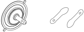
Kontrola filtra
Skontrolujte upchatie filtračnej vložky alebo cudzie predmety v nej. Skontrolujte poškodenie alebo netesnosti nádobky filtra. Vyčistite benzínom alebo v prípade potreby vymeňte.
Poznámka:
Pred montážou nádobky filtra naneste na O-krúžok vrstvu benzínu.


1. Nádobka filtra 2. O-krúžok 3. Filtračná vložka 4. Veko filtra
Motorová jednotka (podrobne)
POZNÁMKA:
Aby ste zabránili náhodnému naštartovaniu prívesného motora počas údržby, vykonajte dostatočné bezpečnostné opatrenia na odpojenie zapaľovacej sústavy. Napríklad odpojte bezpečnostné lanko zo zostavy vypínača motora a koncovku zo sviečky.
Rozložený výkres
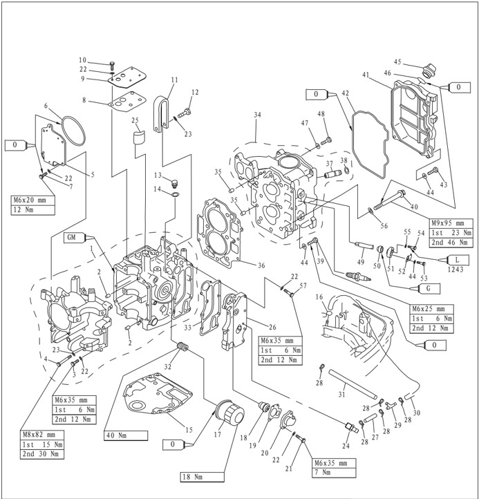
| Číslo dielu | Popis | Popis | Poznámky | ||
|---|---|---|---|---|---|
| 1 | F25-05010000 | Zostava kľukovej skrine | 1 | ||
| 2 | F25-00000014 | φ8x12 | Vodiaci kolík | 2 | |
| 3 | GB/T5782-M6x35 | M6X35 | Skrutka so šesťhrannou hlavou M6X35 | 6 | |
| 4 | GB/T5782-M8x80 | M8X80 | ŠESŤHRANNÁ SKRUTKA M8x80 | 6 | |
| 5 | F25-05000007 | KRYT VYVAŽOVACIEHO VALCA | 1 | ||
| 6 | F25-05000010 | 0 97.5x1.9 | TESNENIE 97.5x1.9 | 1 | |
| 7 | GB/T5783-M6x20 | M6X20 | Skrutka so šesťhrannou hlavou M6X20 | 4 | |
| 8 | F25-05010108 | TESNENIE KRYTU ODVZDUŠŇOVAČA | 1 | ||
| 9 | F25-05010109 | Kryt odvetrania | 1 | ||
| 10 | GB/T5783-M6x20 | M6X20 | Skrutka so šesťhrannou hlavou M6X20 | 4 | |
| 11 | F25-05010106 | ZÁVES MOTORA | 1 | ||
| 12 | GB/T5782-M8x35 | M8X35 | ŠESŤHRANNÁ SKRUTKA M8x35 | 1 | |
| 13 | F15-04000002 | VYPÚŠŤACIA SKRUTKA OLEJA | 1 | ||
| 14 | F15-04000003 | PODLOŽKA | 1 | ||
| 15 | F25-00000013 | TESNENIE MOTORA | 1 | ||
| 16 | F4-04000030 | B | Pružina palivovej hadice "B" | 1 | |
| 17 | F15-07010023 | Olejový filter | 1 | ||
| 18 | F4-04000036 | Termostat | 1 |
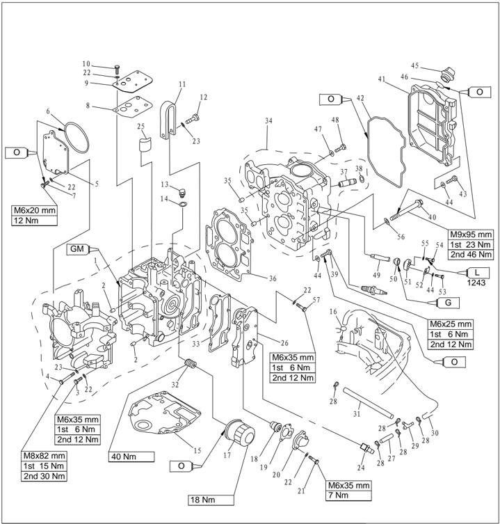
| Číslo dielu | Popis | |||
|---|---|---|---|---|
| 19 | F15-07010022 | F15-07010022 | TESNENIE TERMOSTATU | 1 |
| 20 | F15-07010021 | F15-07010021 | KRYT TERMOSTATU | 1 |
| 21 | GB/T5783-M6x25 M6X25 | GB/T5783-M6x25 M6X25 | SKRUTKA M6x25 | 2 |
| 22 | 6 GB/T97.1-6 | 6 GB/T97.1-6 | PODLOŽKA 6 | 17 |
| 23 | GB/T97.1-8 8 | GB/T97.1-8 8 | PODLOŽKA 8 | 7 |
| 24 | F25-05010113 | F25-05010113 | HADICOVÁ VSUVKA | 1 |
| 25 | F25-05010107 | F25-05010107 | FILTER | 1 |
| 26 | F25-05010112 | F25-05010112 | 1 | |
| 27 | F25-03000008 A | F25-03000008 A | HADICA | 1 |
| 28 | HT-2.5x60 | HT-2.5x60 | SPONA | 5 |
| 29 | F15-05000011 | F15-05000011 | Trojcestná rúrka | 1 |
| 30 | C F25-03000011 | C F25-03000011 | HADICA | 1 |
| 31 | B F25-03000009 | B F25-03000009 | HADICA | 1 |
| 32 | F15-07010003 | F15-07010003 | Spojovacia skrutka | 1 |
| 33 | F25-05010111 | F25-05010111 | 1 | |
| 34 | F25-05050100 | F25-05050100 | 1 | |
| 35 | F25-00000014 φ8x12 | F25-00000014 φ8x12 | Vodiaci kolík | 2 |
| 36 | F25-05040000 | F25-05040000 | 1 | |
| 37 | F25-05050104 | F25-05050104 | PUZDRO VODIDLA VENTILU | 4 |
| 38 | F15-07040105 | F15-07040105 | 4 | |
| 39 | M6X25 GB/T5783-M6X25 | M6X25 GB/T5783-M6X25 | 3 | |
| 40 | F25-05000002 | F25-05000002 | PRÍRUBOVÁ SKRUTKA | 6 |
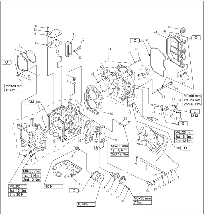
| Číslo dielu | Popis | Popis | Poznámky | ||
|---|---|---|---|---|---|
| 41 | F25-05000005 | 1 | |||
| 42 | F25-05000004 | 1 | |||
| 43 | GB/T5783-M6X20M6X20 | 5 | |||
| 44 | GB/T97.1-6 | 6 | PLOCHÁ PODLOŽKA 6 | 10 | |
| 45 | F15-07050004 | OLEJOVÁ ZÁTKA | 1 | ||
| 46 | O-KRÚŽOK 31-025 | 1 | |||
| 47 | F25-05050007 | TESNENIE | 1 | ||
| 48 | F25-05050006 | Skrutka | 1 | ||
| 49 | F25-02010005 | Anóda | 2 | ||
| 50 | F15-07010009 | Priechodka anódy | 2 | ||
| 51 | F15-07010011 | Veko anódy | 2 | ||
| 52 | F15-07010012 | Doska anódy | 2 | ||
| 53 | GB/T5783-M6X20 | M6X20 | 2 | ||
| 54 | GB/T5783-M5X12 | M5X12 | 2 | ||
| 55 | GB/T97.1-5 | 5 | Plochá podložka 5 | 2 | |
| 56 | F25-050000039 | PLOCHÁ PODLOŽKA 9 | 6 | ||
| 57 | GB/T5783-M6X35 | M6X35 | SKRUTKA M6x35 | 7 |
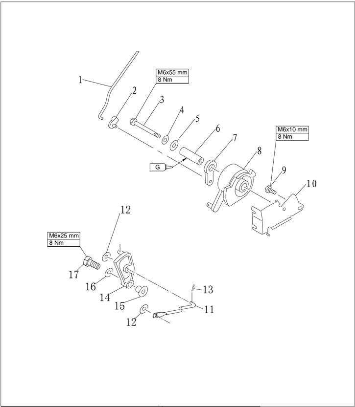
| Číslo dielu | Popis | Popis | Poznámky | ||
|---|---|---|---|---|---|
| 1 | F25-05000008 | ||||
| 2 | F15-07000016 | ||||
| 3 | GB/T5782-M6x55 | M6x55 | SKRUTKA M6x55 | ||
| 4 | GB/T97.1-6 | 6 | PODLOŽKA 6 | ||
| 5 | GB/T96-6 | 6 | VEĽKÁ PODLOŽKA 6 | ||
| 6 | F15-07000012 | ||||
| 7 | F15-07000014 | Hnaná remenica | |||
| 8 | F15-07000013 | Hnacia remenica | |||
| 9 | GB/T5783-M6x10 | M6x10 | SKRUTKA M6x10 | ||
| 10 | F15-07000011 | ||||
| 11 | F25-03030004W | B | SPOJOVACIA TYČ RADENIA | 1 | Typ s elektrickým štartovaním |
| 12 | GB/T96-5 | 5 | VEĽKÁ PODLOŽKA 5 | 2 | Typ s elektrickým štartovaním |
| 13 | F25-05160002 | φ1 | PRUŽINA | 1 | Typ s elektrickým štartovaním |
| 14 | F25-03000027W | RADIACA PLATNIČKA | 1 | Typ s elektrickým štartovaním | |
| 15 | F25-03000028W | Puzdro dorazovej dosky | 1 | Typ s elektrickým štartovaním | |
| 16 | GB/T5287-6 | 6 | HORNÁ PODLOŽKA 6 | 1 | Typ s elektrickým štartovaním |
| 17 | GB/T5783-M6x25 | M6×25 | SKRUTKA M6x25 | 1 | Typ s elektrickým štartovaním |
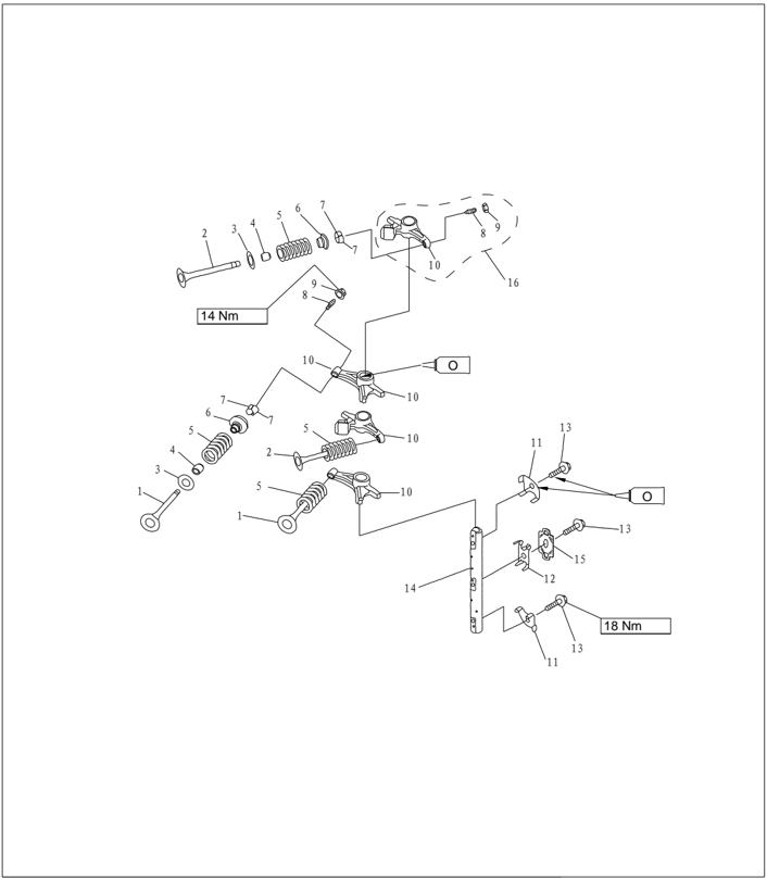
| Číslo dielu | Popis | Popis | Poznámky | ||
|---|---|---|---|---|---|
| F25-05050001 | SACÍ VENTIL | 2 | |||
| F25-05050002 | VÝFUKOVÝ VENTIL | 2 | |||
| F25-05050003 | 4 | ||||
| PS-2700.04.03 | TESNENIE DRIEKU VENTILU | 4 | |||
| F25-05050005 | Ventilová pružina | 4 | |||
| F15-07040006 | 4 | ||||
| F15-07040007 | Klin ventilu | 8 | |||
| F15-07040303 | 1x4 | ||||
| F15-07040304 | Matica | 1x4 | |||
| F25-05050301 | Vahadlo | 1x4 | |||
| 11 | F25-05050009 | A | 2 | ||
| 12 | F25-05050011 | PRUŽINA | 1 | ||
| 13 | F25-05050019 | Skrutka | 3 | ||
| 14 | F25-05050008 | Hriadeľ vahadla | 1 | ||
| 15 | F25-05050012 | B | 1 | ||
| 16 | F25-05050300 | ZOSTAVA VAHADLA | 4 |
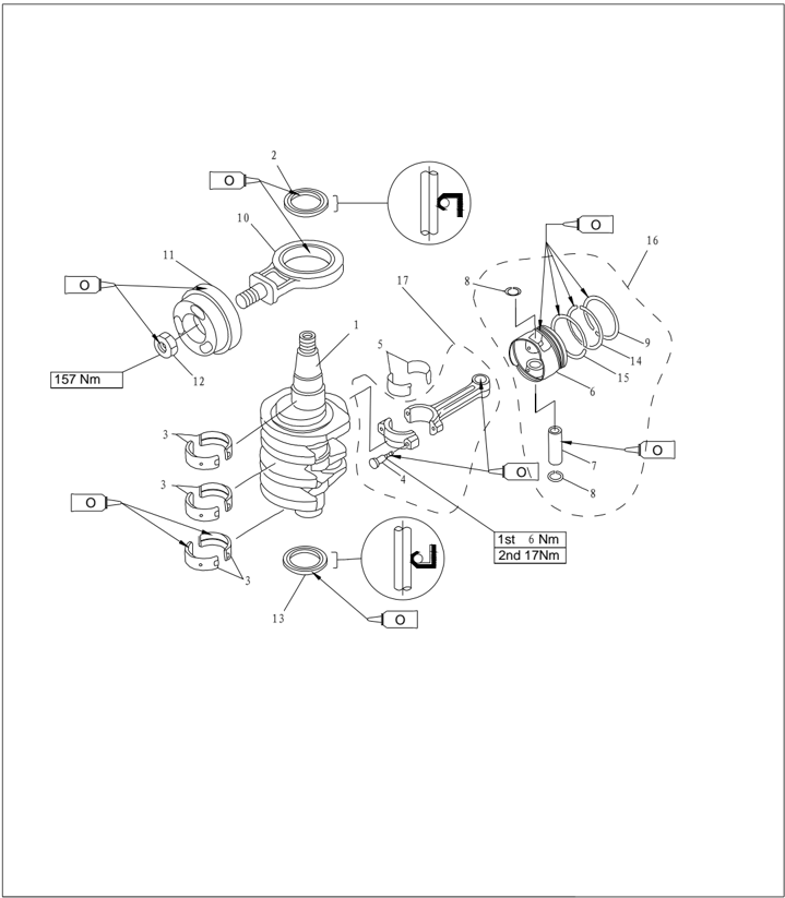
| Číslo dielu | Popis | Popis | Poznámky | ||
|---|---|---|---|---|---|
| 1 | F25-05020001 | Kľukový hriadeľ | 1 | ||
| 2 | F25-05020002 | B | OLEJOVÉ TESNENIE B | 1 | |
| 3 | F25-05010302-1 | Hlavné ložisko | 6 | ||
| F25-05010302-2 | Hlavné ložisko | 6 | UR:HNEDÁ | ||
| 4 | F25-05020204 | 2 | |||
| 5 | F25-05020203-1 | 2 | UR:ČIERNA | ||
| F25-05020203-2 | 2 | ||||
| 6 | F25-05020101 | Piest | 2 | ||
| 7 | F25-05020105 | PIESTNY ČAP | 2 | ||
| 8 | F25-05020106 | POISTNÝ KRÚŽOK | 4 | ||
| 9 | F25-05020102 | I | PIESTNY KRÚŽOK I | 2 | |
| 10 | F25-05020310 | 1 | |||
| 11 | F25-05020301 | VYVAŽOVACÍ PIEST | 1 | ||
| 12 | F25-05000026 | Matica | 1 | ||
| 13 | F25-05020002 | A | OLEJOVÉ TESNENIE A | 1 | |
| 14 | F25-05020103 | Ⅱ | Piestny krúžok | 2 | |
| 15 | F25-05020104 | KOMBINOVANÝ OLEJOVÝ KRÚŽOK | 2 | ||
| 16 | F25-05020100 | ZOSTAVA PIESTA | 2 | ||
| 17 | F25-05020200 | OJNICA | 2 |

| Číslo dielu | Popis | Popis | Poznámky | |
|---|---|---|---|---|
| F4-04000019 | Polkruhové pero | 1 | 4x5.3x13 | |
| F25-05050400 | Zostava olejového čerpadla | 1 | ||
| F25-05000021 | 1 | |||
| F25-05050016 | Vodiaci kolík | 1 | 5x3.8 | |
| F25-05000022 | PUZDRO PRUŽINY | 1 | ||
| F25-05000023 | Rozvodový remeň | 1 | ||
| F25-05050013 | 0A | O-KRÚŽOK A | 1 | 11.6x1.22 |
| F25-05050014 | 0B | O-KRÚŽOK B | 1 | 13.8x1.9 |
| SKRUTKA M10x1.25x40 | 1 | |||
| F25-05050018 | PLOCHÁ PODLOŽKA | 1 | ||
| F25-05050017 | 1 | 33.5x1.9 | ||
| F25-05050015 | 0C | O-KRÚŽOK C | 1 | |
| F25-05050021 | OLEJOVÉ TESNENIE 37X50X7R | 1 | ||
| F25-05050200 | ZOSTAVA VAČKOVÉHO HRIADEĽA | 1 | ||
| GB/T5782-M6x35 | M6x35 | SKRUTKA M6x35 | 4 | |
| GB/T97.1-6 | 6 | PLOCHÁ PODLOŽKA 6 | 4 | |
| GB/T97.1-10 | 10 | PLOCHÁ PODLOŽKA 10 | 1 |
Typ s elektrickým štartovaním
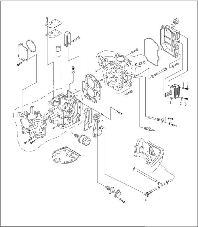
| Číslo dielu | Popis | Popis | Poznámky | |
|---|---|---|---|---|
| F25-05170500W | ZOSTAVA USMERŇOVAČA | 1 | ||
| GB/T97.1-6 | 6 | PODLOŽKA 6 | 2 | |
| GB/T5783-M6x12 | M6X12 | ŠESŤHRANNÁ SKRUTKA M6X12 | 2 | |
| F25-05010400W | ZOSTAVA DÝZY | 1 |
Špeciálne nástroje

Držiak zotrvačníka a sťahovák zotrvačníka
Prípravok na montáž piesta
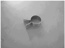
Stláčač ventilových pružín

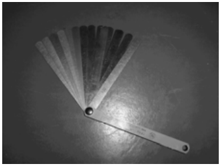
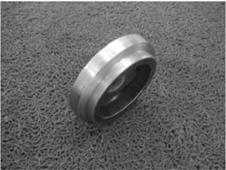
Mierka vôle Kľúč na olejový filter
Kontrola kompresného tlaku
- 1. Naštartujte motor a zahrievajte ho 5 minút. Potom ho zastavte.
- 2. Odstráňte bezpečnostné lanko vypínača motora.
- 3. Odstráňte zapaľovaciu sviečku a pripojte tlakomer k otvoru sviečky.
UPOZORNENIE:
Pred vybratím sviečky vyčistite jej otvor stlačeným vzduchom, aby sa do valca nedostal prach ani cudzie predmety.
- 4. Úplne otvorte sýtič a otáčajte kľukovým hriadeľom pomocou štartéra. Keď sa hodnoty tlakomera ustália, skontrolujte tlak vo valci.
Poznámka:
Počas kontroly tlaku vo valci nemeňte polohu sýtiča.
Pri modeloch s ovládacou skrinkou odpojte spojku plynu, rukou úplne otvorte tyč škrtiacej klapky karburátora a potom zmerajte tlak.
- 5. Ak je nameraný tlak nižší než predpísaný alebo sú medzi valcami rozdiely, pridajte do valcov trochu oleja a meranie zopakujte.
Kompresný tlak: 810 kPa
Poznámka:
Ak tlak vo valci neustále rastie, skontrolujte poškodenie piesta a piestneho krúžku. V prípade potreby ich vymeňte.
Ak tlak vo valci vôbec nerastie, skontrolujte ventilovú vôľu, ventil, sedlo ventilu, vložku valca, veko valca a jeho tesnenie. V prípade potreby nastavte alebo vymeňte.
Prívesný motor je vybavený automatickým dekompresným zariadením, preto sa namerané hodnoty tlaku môžu líšiť.
Kontrola tlaku oleja
- Naštartujte motor a zahrievajte ho 5 minút. Potom ho zastavte.
- Odstráňte tlakový spínač oleja a pripojte tlakomer
Poznámka:
Použite tlakomer vybavený adaptérom so závitom so stúpaním 1/8in.
- Skontrolujte tlak oleja. Tlak oleja (orientačné údaje): 80kPa (voľnobežné otáčky)
Kontrola tlakového spínača oleja
- Odstráňte tlakový spínač oleja a pripojte vákuový tlakomer.
- Na tlakový spínač oleja pôsobte predpísaným tlakom. Skontrolujte jeho vodivosť digitálnym testerom obvodov. Ak nevyhovuje, vymeňte ho
| Tlak | Elektrická priechodnosť |
|---|---|
| Nad 14.7kPa | Nepriechodné |
| Pod 14.7kPa | Priechodné |
Demontáž motorovej jednotky
- Otvorte horný kryt motora.
- Odstráňte štartér.
- Odstráňte plynové lanko.
- Odstráňte karburátor.
- Odstráňte zotrvačník pomocou špeciálneho náradia.
- Odstráňte skrutky spájajúce motorovú jednotku a hornú skriňu.
- Zdvihnite motor a odstráňte kolík.
- Vyberte polkruhové pero.
- Odpojte vodič vypínača motora a uzemňovací vodič.
Držiak zotrvačníka a sťahovák zotrvačníka
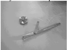
.
- Odpojte lanko plynu (modely s ručným štartovaním) alebo prípojku lanka (modely s elektrickým štartovaním).
- Odstráňte nabíjaciu, osvetľovaciu a impulznú cievku.
- Odstráňte vysokonapäťovú zostavu, jednotku CDI, zapaľovaciu cievku, tlakový spínač oleja a sviečku.
Remenica a rozvodový remeň
- Otočte zotrvačník v smere hodinových ručičiek. Zarovnajte značku '1' na hnanej remenici so značkou ' ▼ ' na veku valca.
UPOZORNENIE:
Neotáčajte zotrvačníkom proti smeru hodinových ručičiek. Inak sa poškodí ventilový mechanizmus.
- Odstráňte rozvodový remeň zo strany hnanej remenice.
UPOZORNENIE:
Neotáčajte remenicou pred upevnením rozvodového remeňa. Inak sa poškodí ventilový mechanizmus.
- Odstráňte skrutku hnanej remenice, hnanú remenicu a polkruhové pero.
Poznámka:
Na odstránenie skrutky hnanej remenice použite držiak zotrvačníka.
Pri odskrutkovávaní rozvodovej remenice neotáčajte vačkovým hriadeľom.
- Odstráňte tesnenie remenice rozvodového remeňa, remenicu a polmesačný klin.
- Skontrolujte praskliny, poškodenie a opotrebovanie remenice a rozvodového remeňa. V prípade potreby ich vymeňte.
- Namontujte polmesačný klin a hnanú remenicu. ▼
Zarovnajte značku '1' na hnanej remenici so značkou ' ' na veku valca. Dočasne utiahnite skrutku hnanej remenice.
UPOZORNENIE:
Neotáčajte remenicou pred upevnením rozvodového remeňa. Inak sa poškodí ventilový mechanizmus.
- Namontujte polmesačný klin a remenicu rozvodového remeňa: ▼
Zarovnajte značku zárezu na remenici rozvodového remeňa so značkou ' ' na kľukovej skrini.
- Namontujte nový rozvodový remeň. Číslo dielu remeňa musí byť zvislé a smerovať nahor.
UPOZORNENIE:
Rozvodový remeň nedeformujte, nekrúťte ani neohýbajte. Inak sa poškodí.
Chráňte rozvodový remeň pred benzínom a olejom.
Neotáčajte remenicou proti smeru hodinových ručičiek. Inak sa poškodí ventilový mechanizmus.
- Otočte rozvodovou remenicou dvakrát v smere hodinových ručičiek, aby sa odstránila vôľa. Skontrolujte správne zarovnanie značiek.
- Utiahnite skrutku a maticu.
Uťahovací moment: skrutka hnanej remenice 38 Nm.
Poznámka:
Odstráňte skrutku hnanej remenice pomocou držiaka zotrvačníka.
Utiahnite maticu remenice rozvodového remeňa špeciálnym nástrčným kľúčom na túto maticu.
Demontáž a kontrola
Kryt valca
Demontáž
- Odstráňte skrutky krytu hlavy valca.
- Odstráňte skrutky veka valca v opačnom poradí čísel vyznačených na veku.
- Odstráňte veko valca a olejové čerpadlo.
- Odstráňte hriadeľ vahadiel, pružinu a zostavu vahadiel.
Poznámka:
Pred odstránením hriadeľa vahadiel povoľte poistnú maticu a nastavovaciu skrutku.
- Pomocou stláčača ventilových pružín odstráňte sací a výfukový ventil.
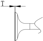
Ventil a vodiace puzdro ventilu
- Skontrolujte šírku sedla ventilu. Ak nie je v predpísanom rozsahu, opravte sedlo. Šírka sedla ventilu:
- Skontrolujte hrúbku okraja ventilu (T). Ak nezodpovedá predpísanej hodnote, ventil vymeňte. Hrúbka okraja ventilu: T
- Skontrolujte priemer drieku ventilu. Ak nezodpovedá predpísanej hodnote, vymeňte ventil. Priemer drieku ventilu:
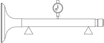
- Zmerajte hádzavosť drieku ventilu. Ak prekračuje limit, vymeňte ventil. Limit hádzavosti drieku ventilu: 0.03mm
- Zmerajte vnútorný priemer vodiaceho puzdra ventilu. Vnútorný priemer vodiaceho puzdra ventilu: 5.500 ~
| Šírka sedla ventilu: sací ventil | 1.84 2.97mm |
|---|---|
| Výfukový ventil | 1.98 3.11mm |
| Sací ventil | 0.8mm |
|---|---|
| Výfukový ventil | 0.9mm |
| Sací ventil | 5.475 5.490mm |
|---|---|
| Výfukový ventil | 5.460 5.475mm |
UPOZORNENIE:
Pri výmene ventilu použite nové vodiace puzdro a olejové tesnenie ventilu.
Ventilová pružina
- Zmerajte voľnú dĺžku ventilovej pružiny. Ak je menšia ako predpísaná hodnota, pružinu vymeňte.
- Zmerajte sklon ventilovej pružiny. Ak prekračuje predpísaný limit, pružinu vymeňte.
Minimálna voľná dĺžka: 38.4 mm
Maximálny limit náklonu: 1.7 mm
Ventilové vahadlo a hriadeľ vahadiel
5.512mm
- Skontrolujte opotrebovanie styčnej plochy medzi ventilovým vahadlom a hriadeľom. V prípade potreby vymeňte.
- Skontrolujte, či vnútorný priemer ventilového vahadla a vonkajší priemer hriadeľa zodpovedajú predpísaným hodnotám.
Vnútorný priemer ventilového vahadla:
16.000 ~ 16.018mm
Vonkajší priemer hriadeľa vahadiel:
15.971 ~ 15.991mm
Vačkový hriadeľ
| Výška | 30.834~31.034mm |
|---|---|
| Priemer základnej kružnice | 25.90~26.10mm |
- Skontrolujte rozmery vačkového hriadeľa.
V prípade potreby vymeňte.
- Skontrolujte hádzavosť vačkového hriadeľa. V prípade potreby ho vymeňte.
Limit kruhovitosti: 0.03mm
- 3 . Skontrolujte priemer hlavného čapu vačkového hriadeľa. V prípade potreby ho vymeňte.
- Skontrolujte praskliny a poškodenie automatického dekompresného zariadenia. V prípade potreby vymeňte vačkový hriadeľ.
Priemer hlavného čapu (HORNÝ):
36.925~36.945mm
Priemer hlavného čapu (STREDNÝ):
36.935~36.955mm
Kontrola olejového čerpadla
- Odstráňte skrutku a olejové čerpadlo.
- Skontrolujte vôľu rotora olejového čerpadla. Ak nezodpovedá špecifikácii, vymeňte ho.
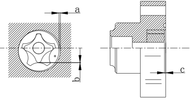
| Vôľa medzi vonkajším rotorom a skriňou a | 0.09~0.15mm |
|---|---|
| Vôľa medzi vonkajším a vnútorným rotorom b | 0.12mm |
| Vôľa medzi rotorom a krytom c | 0.03~0.08mm |
Výmena vodiaceho puzdra ventilu
- Vyrazte vodiace puzdro ventilu zo strany spaľovacej komory.
- Zarazte nové vodiace puzdro zo strany hornej časti veka valca.
Poznámka:
Pred montážou naneste olej na povrch vodidla.
- Výstružníkom vystružte vnútorný priemer rúrky na predpísanú hodnotu.
Vnútorný priemer vedenia ventilu: 5.500
~ 5.512mm
Poznámka:
Pri vyťahovaní výstružníka ním neotáčajte proti smeru hodinových ručičiek.
Kontrola sedla ventilu
- Odstráňte karbón z ventilu.
- Na tesniacu plochu sedla ventilu rovnomerne naneste tenkú vrstvu modrej kontrolnej farby.
- Zabrúste ventil do sedla pomocou nástroja na zabrusovanie ventilov.
- Zmerajte šírku sedla ventilu.
Plocha ventilu je pokrytá kontrolnou modrou farbou.
Ak ventil a sedlo nelícujú alebo šírka sedla nezodpovedá predpísanej hodnote, opracujte a zabrúste sedlo ventilu.
Ak styčná plocha nie je rovnomerná, vymeňte vodiace puzdro ventilu.
Šírka sedla ventilu: 0.9
~ 1.1mm
Frézovanie sedla ventilu
- Na úpravu šírky sedla ventilu použite frézu 45 o. Otáčajte frézou v smere hodinových ručičiek, kým nebude povrch sedla hladký.
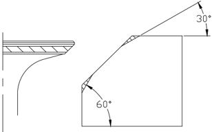
- Ak je sedlo vycentrované na dosadacej ploche ventilu, ale je príliš široké, zúžte ho frézou 30 o na hornom okraji a frézou 60 o na dolnom okraji.
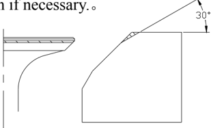
- Ak je sedlo príliš úzke a na hornom okraji plochy ventilu, použite frézu 30 o na úpravu horného okraja sedla a v prípade potreby frézu 45 o na úpravu jeho šírky. 。
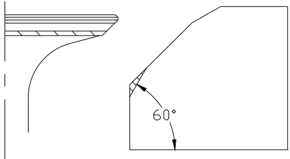
- Ak je tesniaca plocha ventilu príliš úzka a na dolnom okraji plochy ventilu, použite frézu 60 o na úpravu dolného okraja sedla a v prípade potreby frézu 45 o na úpravu jeho šírky
- Rovnomerne naneste tenkú vrstvu brúsnej pasty na sedlo ventilu a zabrúste ventil pomocou zabrusovacieho prípravku.
- Odstráňte zvyšnú brúsnu pastu.
- Znova skontrolujte šírku sedla ventilu.
UPOZORNENIE:
Ventil nezabrusujte nadmerne. Nástroj otáčajte rovnomerne a tlačte nadol silou 40~50N. Zabrusovacou pastou neznečistite tlačnú tyč ani vodiace puzdro ventilu.
Montáž ventilu
- Namontujte nové olejové tesnenie ventilu a naneste motorový olej do vodiaceho puzdra.
- Postupne namontujte ventil, sedlo pružiny, pružinu a tanier pružiny.
- Stláčačom stlačte ventilovú pružinu a namontujte klin ventilu.
- Jemne poklepte na tanier pružiny plastovým alebo gumovým kladivom, aby sa upevnil klin ventilu.
Montáž veka valca
- Pomocou špeciálneho náradia namontujte nové olejové tesnenie.
- Vložte vačkový hriadeľ do veka valca zo strany olejového čerpadla.
- Skontrolujte, či drážkovanie smeruje k spojovacej ploche valca. V prípade potreby nastavte.
- Namontujte zostavu vahadiel, pružinu a hriadeľ vahadiel.
- Namontujte olejové čerpadlo.
Poznámka:
Uistite sa, že značka vonkajšieho rotora smeruje k veku olejového čerpadla.
- Zarovnajte hnací hriadeľ olejového čerpadla s kolíkom vačkového hriadeľa a namontujte čerpadlo.
UPOZORNENIE:
Pred montážou olejového čerpadla sa uistite, že olejový kanál je priechodný, a naplňte čerpadlo olejom.
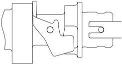
Kľuková skriňa
Demontáž
- Odstráňte olejový filter špeciálnym nástrojom. POZNÁMKA:
Pod olejový filter položte handru
Kľúč na olejový filter
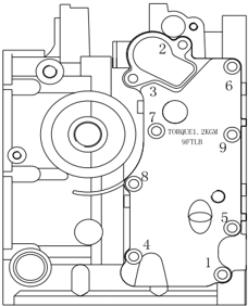
- Odstráňte skrutky v poradí znázornenom na obrázku.
- Odstráňte kryt termostatu, vonkajší kryt výfuku, tesnenie a kolíky. 。 Vyčistite povrch anódy a skontrolujte ju. Pri nadmernej korózii ju vymeňte. Skontrolujte, či vonkajší kryt výfuku nie je prasknutý, zdeformovaný alebo skorodovaný. V prípade potreby ho vymeňte.
- Odstráňte kryt vyvažovacieho valca a potom maticu a piest vyvažovacieho valca.
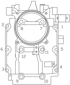
- Odstráňte skrutky kľukovej skrine v poradí znázornenom na obrázku a odstráňte základňu.
- Odstráňte skrutky a veko ojnice, vyberte kľukový hriadeľ a zostavu ojnice a piesta.
- Kliešťami odstráňte poistný krúžok piestneho čapu a odstráňte čap a piest.
- Odstráňte olejové tesnenie, kolík a hlavné ložisko.
Piest a ojnica vyvažovacieho valca
- 1 . Skontrolujte, či piest vyvažovacieho valca nie je prasknutý alebo poškodený. V prípade potreby ho vymeňte.
- Skontrolujte, či zostava ojnice vyvažovacieho valca nie je prasknutá alebo poškodená. V prípade potreby ju vymeňte.
Piest
- Zmerajte vonkajší priemer piesta v predpísanom meracom bode. Ak je mimo špecifikácie, piest vymeňte.
- Skontrolujte vnútorný priemer piestneho čapu. Ak je mimo predpísanej hodnoty, vymeňte
Priemer piesta
64.950 ~ 64.965 mm
Merací bod○
a : 2 mm
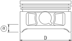
Vnútorný priemer piestneho čapu: 15.974
~ 15.985mm
Vŕtanie valca
- Zmerajte priemer valca samostatne v meracích bodoch ○ 1 ,○ 2 ,○ 3 . V každom bode merajte v miestach D1, D3, D5 rovnobežných s kľukovým hriadeľom a v miestach D2, D4, D6 kolmých na kľukový hriadeľ. ②
- Vypočítajte limity kužeľovitosti a ovality. Ak sú mimo špecifikácie, vymeňte kľukovú skriňu.
Výška meracieho bodu
○ 1 20 mm ;
○ 2 40 mm ;
○ 3 60 mm
Vŕtanie valca
65.000 ~ 65.015 mm
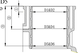
Limit kužeľovitosti: 0.08mm
(D1-D5, D2-D6)
Limit ovality: 0.05 mm
(D2-D1, D6-D5)
Vonkajší priemer piestneho čapu
Zmerajte vonkajší priemer piestneho čapu. Ak je mimo predpísanej hodnoty, vymeňte ho.
Vonkajší priemer piestneho čapu: 15.965
~ 15.985mm
Piestny krúžok
- Pomocou piesta zatlačte piestny krúžok rovnobežne do predpísaného meracieho miesta vo valci (20mm od styčnej plochy).
- Škáromerom zmerajte vôľu v zámku. Ak je mimo špecifikácie, vymeňte piestny krúžok.
Vôľa v zámku (po montáži):
Horný krúžok
- krúžok
Olejový krúžok
0.15 ~ 0.30mm
0.30 ~ 0.50mm
0.20 ~ 0.70mm
- Namontujte krúžok na piest a mierkou vôle zmerajte bočnú vôľu medzi krúžkom a jeho drážkou. Ak nezodpovedá špecifikácii, krúžok vymeňte.
Bočná vôľa
Horný krúžok
0.02 ~ 0.06 mm
- krúžok: 0.02
~ 0.06 mm
Olejový krúžok: 0.04
~ 0.18 mm
Vnútorný priemer malého oka ojnice
Zmerajte vnútorný priemer malého oka ojnice. Ak je mimo predpísanej hodnoty, vymeňte ju. 。
Vnútorný priemer malého oka ojnice:
15.985 ~ 15.998mm
Bočná vôľa veľkého oka ojnice
Zmerajte bočnú vôľu veľkého oka ojnice. Ak je mimo predpísanej hodnoty, vymeňte ojnicu, kľukový hriadeľ alebo oba diely.
Bočná vôľa veľkého oka ojnice:
0.05 ~ 0.22 mm
Kľukový hriadeľ
- Zmerajte priemer hlavných čapov kľukového hriadeľa a priemer a šírku ojničných čapov. Ak nezodpovedajú špecifikácii, vymeňte kľukový hriadeľ.
| Priemer hlavného čapu kľukového hriadeľa | 42.984~43.000mm |
|---|---|
| Priemer ojničného čapu | 32.984~33.000mm |
| Šírka ojničného čapu | 21.000~21.070mm |
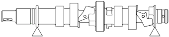
- Zmerajte hádzavosť kľukového hriadeľa. Ak je mimo predpísanej hodnoty, vymeňte ho.
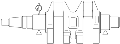
Limit hádzavosti kľukového hriadeľa: 0.05mm
Olejová vôľa ojničného čapu
- Položte kus plastového meracieho vlákna na ojničný čap rovnobežne s kľukovým hriadeľom.
- Namontujte ojnicu a hlavné ložisko na ojničný čap.
- Utiahnite skrutky ojnice predpísaným momentom.
- Odstráňte ojnicu a zmerajte stlačenú šírku plastovej mierky vôle. Ak je mimo predpísanej hodnoty, vymeňte hlavné ložisko.
Uťahovací moment
Prvé utiahnutie 6 Nm
Druhé utiahnutie 17 Nm
Olejová vôľa: 0.020
~ 0.052mm
Poznámka:
Ojnicou neotáčajte, kým meranie nie je dokončené.
Olejová vôľa hlavného čapu
- Vyčistite hlavné ložisko, hlavný čap a montážne plochy kľukovej skrine a jej základne.
- Namontujte hlavné ložisko a kľukový hriadeľ do kľukovej skrine.
- Na hlavný čap položte plastovú meraciu pásku rovnobežne s kľukovým hriadeľom.
Poznámka:
Plastovú meraciu pásku neklaďte na olejový otvor hlavného čapu.
- Namontujte hlavné ložisko do základne kľukovej skrine a základňu namontujte na skriňu.
- Podľa číselného poradia na základni kľukovej skrine utiahnite skrutky predpísanými momentmi.
Uťahovacie momenty:
| Prvé utiahnutie | M8 | 15 Nm |
|---|---|---|
| Druhé utiahnutie | M8 | 30 Nm |
| Prvé utiahnutie | M6 | 6 Nm |
| Druhé utiahnutie | M6 | 12 Nm |
- Odstráňte kľukovú skriňu a zmerajte stlačenú šírku každej plastovej meracej pásky. Ak nezodpovedá špecifikácii, vymeňte hlavné ložisko.
Olejová vôľa
0.012 ~ 0.044mm
Poznámka:
Pred dokončením merania neotáčajte kľukovým hriadeľom.
Kľuková skriňa a jej základňa
- Skontrolujte, či základňa kľukovej skrine a skriňa nie sú prasknuté, poškodené alebo opotrebované. V prípade potreby ich vymeňte.
- Skontrolujte kanál chladiacej vody na nečistoty alebo upchatie. V prípade potreby ho vyčistite.
Kompletná montáž
Montáž piesta a ojnice
Namontujte piest, ojnicu, piestny čap a poistný krúžok piestneho čapu.
Poznámka:
Pri montáži sa uistite, že značka na ojnici je na rovnakej strane ako značka na dne piesta.
Montáž piestnych krúžkov
- Namontujte olejový krúžok, krúžok 2 a horný krúžok.
Poznámka:
Pri montáži krúžku 2 sa uistite, že značka smeruje k dnu piesta.
- Obrázok medzier piestnych krúžkov
Vôľa v zámku olejového krúžku 1 (dolná lišta)
Vôľa v zámku olejového krúžku 2 (rozperný krúžok)
Vôľa v zámku olejového krúžku 3 (horná lišta)
Vôľa v zámku 2. piestneho krúžku 4
Vôľa v zámku horného piestneho krúžku 5
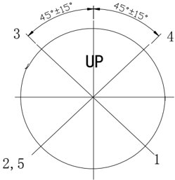
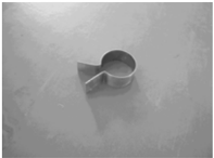
Montáž piesta
Pomocou prípravku na montáž piesta namontujte piest a uistite sa, že značka *Up" na dne piesta smeruje k zotrvačníku.
Poznámka:
Pri montáži naneste motorový olej na piest a boky piestnych krúžkov.
Montáž kľukového hriadeľa
.
- Namontujte hlavné ložisko do kľukovej skrine
Poznámka:
Vložte výstupok hlavného ložiska do príslušnej drážky kľukovej skrine.
- Namontujte ojnicu vyvažovacieho valca na kľukový hriadeľ.
- Namontujte kľukový hriadeľ do kľukovej skrine. Namontujte olejové tesnenie.
Poznámka:
Pred montážou naneste motorový olej na vnútornú stranu olejového tesnenia.
- Namontujte veko ojnice na ojnicu a utiahnite skrutku ojnice predpísaným momentom v dvoch krokoch.
Uťahovací moment
Prvé utiahnutie
6 Nm
Druhé utiahnutie 17 Nm
Poznámka:
Zarovnajte značku na veku ojnice so značkou na ojnici.
Pred montážou naneste motorový olej na skrutku ojnice.
Montáž motorovej jednotky
- Namontujte hlavné ložisko do základne kľukovej skrine.
- Naneste tekutý tmel na styčnú plochu základne kľukovej skrine a namontujte vodiaci kolík a základňu. Skrutky utiahnite dvakrát podľa poradia na obrázku vpravo.
Uťahovací moment
Poznámka:
Pred montážou naneste motorový olej na pohyblivé diely.
Pred montážou naneste motorový olej na skrutku.
- Namontujte piest vyvažovacieho valca a utiahnite jeho maticu predpísaným momentom. Uťahovací moment: 157 Nm
Poznámka:
Pred montážou naneste motorový olej na maticu.
- Namontujte nové O-krúžky a kryt vyvažovacieho valca a utiahnite skrutku predpísaným momentom.
Uťahovací moment
12 Nm
Poznámka:
Pred montážou naneste motorový olej na skrutku.
- Namontujte olejový filter špeciálnym nástrojom a utiahnite ho predpísaným momentom. Uťahovací moment: 18 Nm
Poznámka:
Pred montážou nalejte motorový olej do olejového kanála.
| Prvé utiahnutie | M8 | 15 Nm |
|---|---|---|
| Druhé utiahnutie | M8 | 30 Nm |
| Prvé utiahnutie | M6 | 6 Nm |
| Druhé utiahnutie | M6 | 12 Nm |
.
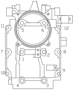

- Namontujte vonkajší kryt výfuku, termostat a kryt termostatu. Skrutky utiahnite dvakrát podľa poradia na obrázku.
- Namontujte vodiaci kolík, tesnenie valca a zostavu veka valca.
- Skontrolujte polohu drážky polmesačného klinu na vačkovom hriadeli.
- Skrutky veka valca utiahnite v dvoch etapách predpísaným momentom podľa poradia na obrázku vpravo. Uťahovací moment:
Uťahovací moment
Prvé utiahnutie
6 Nm
Druhé utiahnutie
12 Nm
| Prvé utiahnutie | M9 | 23 Nm |
|---|---|---|
| Druhé utiahnutie | M9 | 46 Nm |
| Prvé utiahnutie | M6 | 6 Nm |
| Druhé utiahnutie | M6 | 12 Nm |
Poznámka:
Nepoužívajte staré tesnenie
- Namontujte rozvodovú remenicu, hnanú remenicu, rozvodový remeň a odvetrávaciu rúrku.
- Poznámka:
Pri montáži sa uistite, že značka na hnanej remenici je zarovnaná so značkou " ▼ " na veku valca a značka na remenici rozvodového remeňa so značkou " ▼ " na kľukovej skrini.
- Nastavte ventilovú vôľu.
- Namontujte kryt veka valca a utiahnite skrutky podľa poradia na obrázku vpravo.
- Namontujte konzolu lanka plynu a mechanizmus plynovej rukoväti.
- Pri modeloch s elektrickým štartovaním najprv namontujte radiacu dorazovú tyč.
- Namontujte tlakový spínač oleja, zapaľovaciu cievku, zostavu jednotky C.D.I. a zostavu usmerňovača a regulátora.
- Namontujte impulznú, osvetľovaciu a nabíjaciu cievku.
- Namontujte palivový systém.
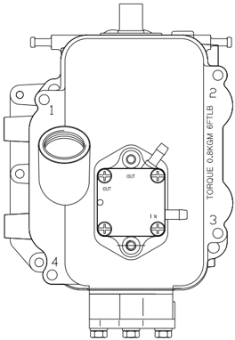
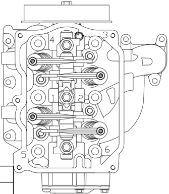
Horná jednotka
Horný kryt motora
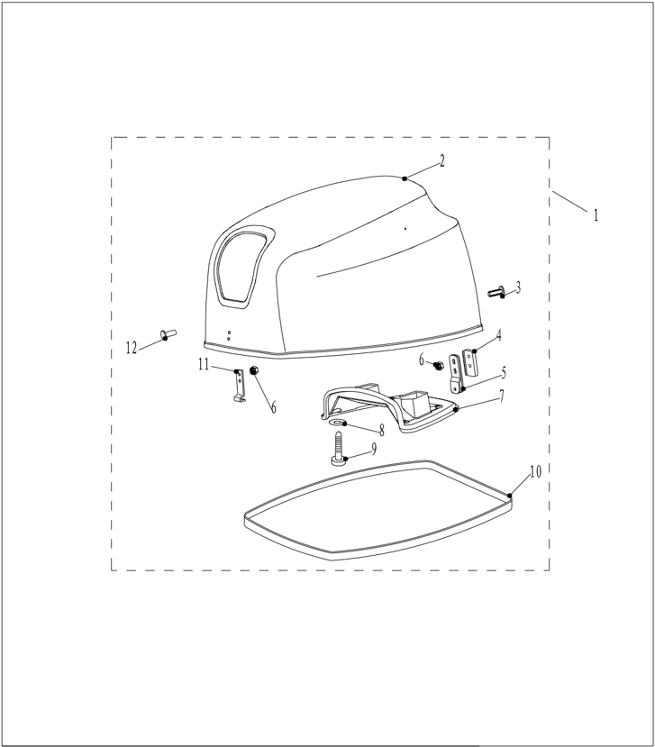
Rozložený výkres
| Číslo dielu | Popis | Poznámky | |
|---|---|---|---|
| F25-06000000 | Zostava horného krytu motora | ||
| F25-06000001 | Horný kryt motora | ||
| F25-06000007 | SKRUTKA S PLOCHOU HLAVOU | ||
| F25-06000005 | |||
| F25-06000100 | |||
| GB/T6184-M6 | MATICA M6 | ||
| F25-06000003 | |||
| F4-06000004 | GUMOVÁ PODLOŽKA | ||
| F25-06000002 | Tesnenie | ||
| F25-06000004 | PREDNÝ HÁK | ||
| F25-06000006 | B | SKRUTKA S PLOCHOU HLAVOU "B" |
- Odstráňte gumové tesnenie.
- Odstráňte skrutku veka tlmiča horného krytu a gumovú podložku.
- Odstráňte veko tlmiča horného krytu.
- Odstráňte zaisťovací a závesný hák.
- Skontrolujte, či horný kryt nie je prasknutý alebo poškodený. V prípade potreby ho vymeňte.
- Skontrolujte praskliny alebo poškodenie gumového tesnenia. V prípade potreby ho vymeňte.
- Skontrolujte praskliny alebo poškodenie veka tlmiča horného krytu. V prípade potreby ho vymeňte.
- Skontrolujte praskliny, deformáciu alebo poškodenie zaisťovacieho a závesného háka. V prípade potreby ich vymeňte.
Demontáž a kontrola
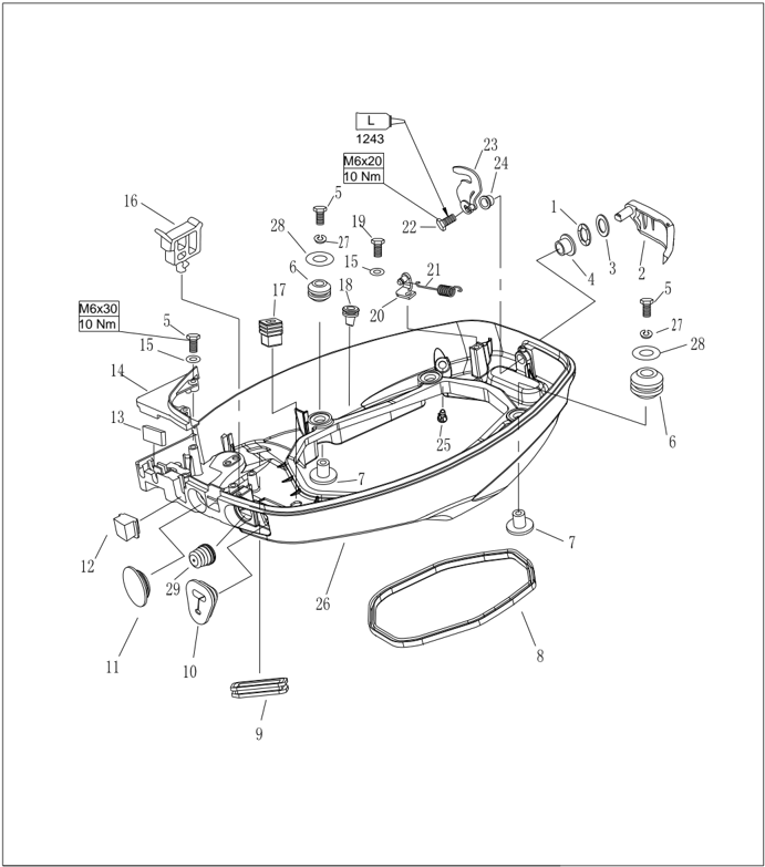
Dolný kryt motora
Rozložený výkres
| Číslo dielu | Popis | Poznámky | ||
|---|---|---|---|---|
| F15-05000023 | F15-05000023 | Vlnitá podložka | 1 | |
| F25-03010000 | 1 | |||
| F25-03000015 | PODLOŽKA | 1 | ||
| F15-05000022 | PUZDRO A | 1 | ||
| GB/T5783-M6x30 | M6x30 | Skrutka so šesťhrannou hlavou M6X30 | 6 | |
| F25-03000006 | F25-03000006 | Tlmič | 4 | |
| F25-03000007 | F25-03000007 | PUZDRO TLMIČA | 4 | |
| F25-03000002 | F25-03000002 | 1 | ||
| F15-05000003 | F15-05000003 | 1 | ||
| F15-01000015 | F15-01000015 | NÁVLEK LANKA | 1 | |
| F25-03000003 | F25-03000003 | 1 | ||
| F25-03000013 | F25-03000013 | 1 | ||
| F15-05000017 | Gumové tesnenie | 1 | ||
| F25-03000014 | 1 | |||
| GB/T97.1-6 | 6 | PODLOŽKA 6 | 3 |
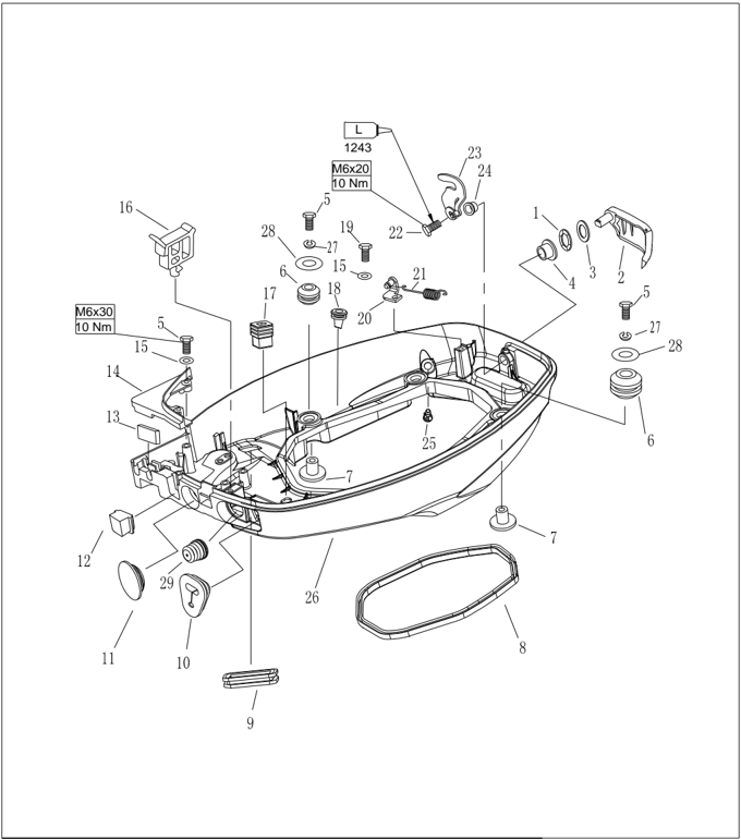
| Číslo dielu | Popis | Poznámky | ||
|---|---|---|---|---|
| 16 | F15-05000008A | Spona A | 1 | |
| 17 | F15-05000033 | NÁVLEK PÁKY | 1 | |
| 18 | F25-03000005 | GUMOVÁ VSUVKA | 6 | |
| 19 | GB/T5783-M6x20M6x20 | Skrutka so šesťhrannou hlavou M6X20 | 1 | |
| 20 | F25-03000019 | 1 | ||
| 21 | F15-05000026 | Ťažná pružina | 1 | |
| 22 | M6x12 GB/T5783-M6x12 | ŠESŤHRANNÁ SKRUTKA M6x12 | 1 | |
| 23 | F25-03020000 | 1 | ||
| 24 | F15-05000036 B | PUZDRO B | 1 | |
| 25 | F15-05000009 | PLASTOVÁ VSUVKA | 1 | |
| 26 | F25-03000001 | Dolný kryt motora | 1 | |
| 27 | GB/T93-6 | 6 Pružná podložka 6 | 4 | |
| 28 | 6 F25-00000004 | Veľká podložka 6 | 4 | |
| 29 | F15-05000006 | VLNITÝ OBAL | 1 |
Typ s elektrickým štartovaním:
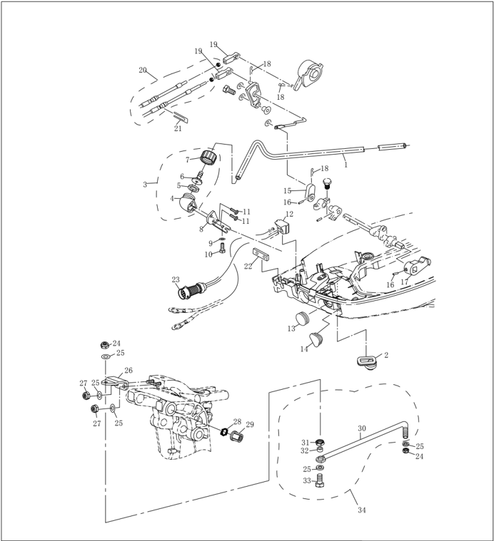
| Číslo dielu | Popis | Poznámky | |
|---|---|---|---|
| 1 | |||
| 2 | |||
| 3 | |||
| 4 | |||
| 5 | |||
| 6 | |||
| 7 | |||
| 8 | |||
| 9 | |||
| 10 | |||
| 11 | |||
| 12 | |||
| 13 | |||
| 14 | |||
| 15 | |||
| 16 | |||
| 17 | |||
| 18 | |||
| 19 | |||
| 20 |
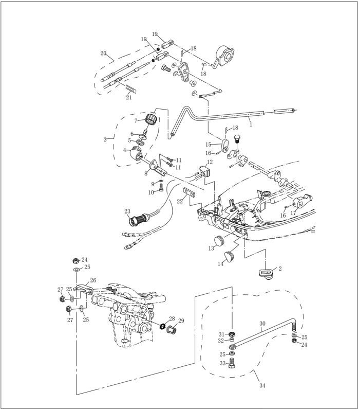
| Číslo dielu | Popis | Popis | |
|---|---|---|---|
| 21 | |||
| 22 | |||
| 23 | |||
| 24 | 3/8" | 3/8" | |
| 25 | |||
| 26 | |||
| 27 | |||
| 28 | |||
| 29 | |||
| 30 | |||
| 31 | |||
| 32 | |||
| 33 | |||
| 34 |
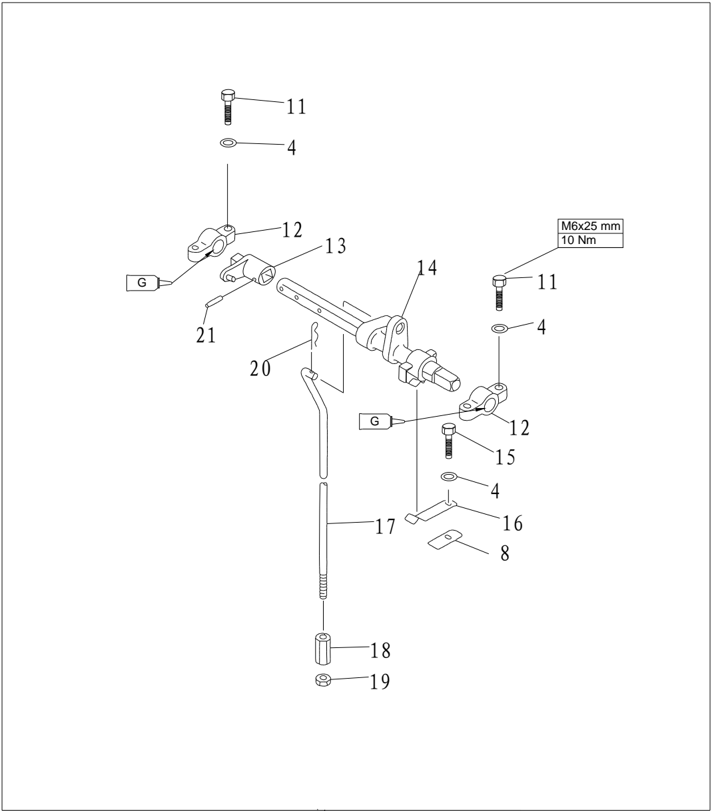
| Číslo dielu | Popis | Popis | Poznámky |
|---|---|---|---|
| GB/T5783-M6x25 | M6x25 | SKRUTKA M6x25 | |
| GB/T97.1-6 | 6 | PODLOŽKA 6 | |
| F15-05040002 | Držiak radiacej tyče | ||
| F25-03030001 | Vahadlo dorazu | ||
| F15-05040100 | PÁKA RADIACEJ TYČE | ||
| GB/T5783-M6x20 | M6x20 | SKRUTKA M6x20 | |
| F15-05000031 | PRUŽINA | ||
| F25-03030002 | Radiaca tyč | ||
| F25-03030002 | Radiaca tyč | ||
| F15-05000035 | Valcová matica | ||
| GB/T6172.1-M6 | M6 | MATICA M6 | |
| F15-00000012 | PRUŽINA | ||
| GB/T879.4-3x20 | PRUŽNÝ KOLÍK |
Demontáž a kontrola
- Odstráňte gumovú zátku, vlnitý návlek a návlek lanka plynu.
Odstráňte zostavu kabeláže C.D.I. (platí pre model s predným ovládaním a elektrickým štartovaním).
- Odstráňte skrutky upevňujúce kryciu dosku spodného krytu a odstráňte dosku. Odstráňte gumové tesnenie. Odstráňte otvorenú obmedzovaciu platničku a štvorcovú gumovú zátku. (Platí pre model s predným ovládaním a elektrickým štartovaním).
- Odstráňte skrutky uzamykacej rukoväti horného krytu, rukoväť a uzamykací blok.
- Odstráňte puzdro A a puzdro B uzamykacej rukoväti horného krytu.
- Odstráňte vlnitú podložku.
- Odstráňte upevňovaciu skrutku držiaka radiacej tyče.
- Vyberte závlačku radiacej tyče.
- Odstráňte radiacu tyč, pružný kolík a vahadlo dorazu.
- Odstráňte pružinovú platničku radenia.
- Skontrolujte praskliny alebo poškodenie spodného krytu. V prípade potreby ho vymeňte.
- Skontrolujte, či uzamykacia rukoväť a uzamykací blok horného krytu nie sú prasknuté alebo poškodené. V prípade potreby ich vymeňte.
- Skontrolujte, či vlnitá podložka a puzdro A uzamykacej rukoväti nie sú prasknuté alebo poškodené. V prípade potreby ich vymeňte.
- Skontrolujte praskliny alebo poškodenie držiaka radiacej tyče a vahadla dorazu. V prípade potreby ich vymeňte.
- Skontrolujte, či pružinová platnička radenia nie je prasknutá, zdeformovaná alebo poškodená. V prípade potreby ju vymeňte.
Riadiaca rukoväť
Rozložený výkres

| Číslo dielu | Popis | Poznámky | ||
|---|---|---|---|---|
| 1 | F25-01030101 | |||
| 2 | F25-01030002 | |||
| 3 | POISTNÁ MATICA M10x1.25 | |||
| 4 | Matica M10×1.25 | |||
| 5 | F15-01000013 | |||
| 6 | F15-01000011 | () | ||
| 7 | F15-00000007 | |||
| 8 | F25-00000009 | Spojka radiacej tyče | ||
| 9 | GB/T97.1-6 | 6 | Plochá podložka 6 | |
| 10 | F15-00000012 | Pružina svorky | ||
| 11 | F15-00000009 | Vlnitá podložka | ||
| 12 | F15-00000008 | Prírubová rúrka | ||
| 13 | GB/T5783-M6 x 35 | M6×35 | Šesťhranná skrutka M6×35 | |
| 14 | F15-01000012 | Nylonová podložka | ||
| 15 | F15-01000008 | PODLOŽKA | ||
| 16 | F15-01000009 | Vlnitá podložka | ||
| 17 | F15-01000007 | () | Puzdro rukoväti | |
| 18 | GB/T91-1.6x12 | φ1.6×12 | ZÁVLAČKA Φ1.6x12 | |
| 19 | F15-01030200 | Skrutka | ||
| 20 | F4-01090401 |
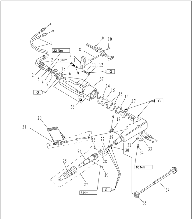
| Číslo dielu | Popis | Poznámky | |||
|---|---|---|---|---|---|
| 21 | T15-01020003 | 1 | |||
| 22 | GB/T848-10 | 10 | MALÁ PODLOŽKA 10 | 1 | |
| 23 | GB/T827-2 x 5 | 2×5 | 1 | ||
| 24 | F4-01090301 | 1 | |||
| 25 | F4-01090302 | Guma rukoväti | 1 | ||
| 26 | GB/T820-M5x25 | Skrutka M5X25 | 1 | ||
| 27 | F4-01090300 | 1 | |||
| 28 | F4-01090303 | 1 | |||
| 29 | F4-01090007 | 1 | |||
| 30 | F4-01090006 | PUZDRO | 1 | ||
| 31 | F15-01030005 | Podpera | 1 | ||
| 32 | GB/T5783-M6X20 | M6×20 | ŠESŤHRANNÁ SKRUTKA M6x20 | 2 | |
| 33 | F15-01030001 | Riadiaca rukoväť | 1 | ||
| 34 | F15-01030100 | 1 | |||
| 35 | F4-01090003 | TRENIE | 1 | ||
| 36 | GB/T6170-M6 | M6 | MATICA M6 | 1 | |
| 37 | F25-01030001 | KONZOLA RUKOVÄTI | 1 |
Demontáž a kontrola
- 1. Odstráňte konzolu rukoväti, radiacu rukoväť a rukoväť riadenia.
- 2. Odstráňte kryt riadiacej rukoväti.
- 3. Odstráňte puzdro rukoväti, podložku puzdra a vlnitú podložku.
- 4. Odstráňte závlačku a skrutku nastavenia trenia
- 5. Odstráňte riadiacu rukoväť.
- 6. Odstráňte plynové lanko.
- 7. Odstráňte podperu plynovej páky a plynovú páku.
- 8. Odstráňte vypínač motora.
- 9. Skontrolujte, či radiaca rukoväť nie je prasknutá alebo poškodená. V prípade potreby ju vymeňte.
- Skontrolujte praskliny alebo poškodenie rukoväti riadenia. V prípade potreby ju vymeňte.
- Skontrolujte praskliny alebo poškodenie puzdra, jeho podložky a vlnitej podložky. V prípade potreby ich vymeňte.
- Skontrolujte opotrebovanie alebo praskliny lanka plynu. V prípade potreby ho vymeňte.
- Skontrolujte elektrickú vodivosť vypínača motora. Ak nezodpovedá špecifikácii, vymeňte ho.
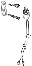
Odstráňte poistnú doštičku:
Vodivé
Namontujte poistnú doštičku:
Nevodivé
Stlačte tlačidlo vypínača: Vodivé
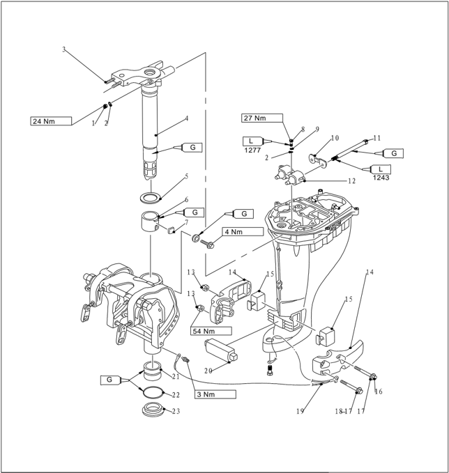
Konzola
Rozložený výkres
| Číslo dielu | Popis | Popis | ||
|---|---|---|---|---|
| 1 | GB/T889.2-M8x1.0 | GB/T889.2-M8x1.0 | GB/T889.2-M8x1.0 | 2 |
| 2 | GB/T97.1-8 | 8 | PODLOŽKA 8 | 5 |
| 3 | F25-01020002 | 2 | ||
| 4 | F25-01020001 | 1 | ||
| F25-01020001S | 1 | |||
| 5 | F25-01000003 | Horná podložka | 1 | |
| 6 | F25-01000001 | Horné puzdro | 1 | |
| 7 | F25-01000002 | TRECIA PLATNIČKA | 1 | |
| 8 | GB/T5783-M8x30 | M8×30 | SKRUTKA M8x30 | 3 |
| 9 | GB/T93-8 | 8 | PRUŽNÁ PODLOŽKA 8 | 3 |
| 10 | F25-02000015 | Doska | 1 | |
| 11 | F25-02000016 | DLHÁ SKRUTKA | 2 | |
| 12 | F25-02030000 | 1 | ||
| 13 | F25-00000005 | M10 | MATICA M10 | 4 |
| 14 | F25-00000001 | 2 | ||
| 15 | F25-00000002 | 2 | ||
| 16 | F25-00000006 | M10×120 | SKRUTKA M10x120 | 2 |
| 17 | GB/T97.1-10 | 10 | PODLOŽKA 10 | 4 |
| 18 | F25-00000007 | M10×80 | SKRUTKA M10x80 | 2 |
| 19 | F25-02000002 | 1 | ||
| 20 | F25-00000003 | 1 | ||
| 21 | F25-01000004 | Dolné puzdro | 1 | |
| F25-01000004S | Dolné puzdro | 1 | ||
| 22 | F25-01000005 | O | O-krúžok | 1 |
| F25-01000005S | O | O-krúžok | 1 | |
| 23 | F25-01000006 | Dolná podložka | 1 |
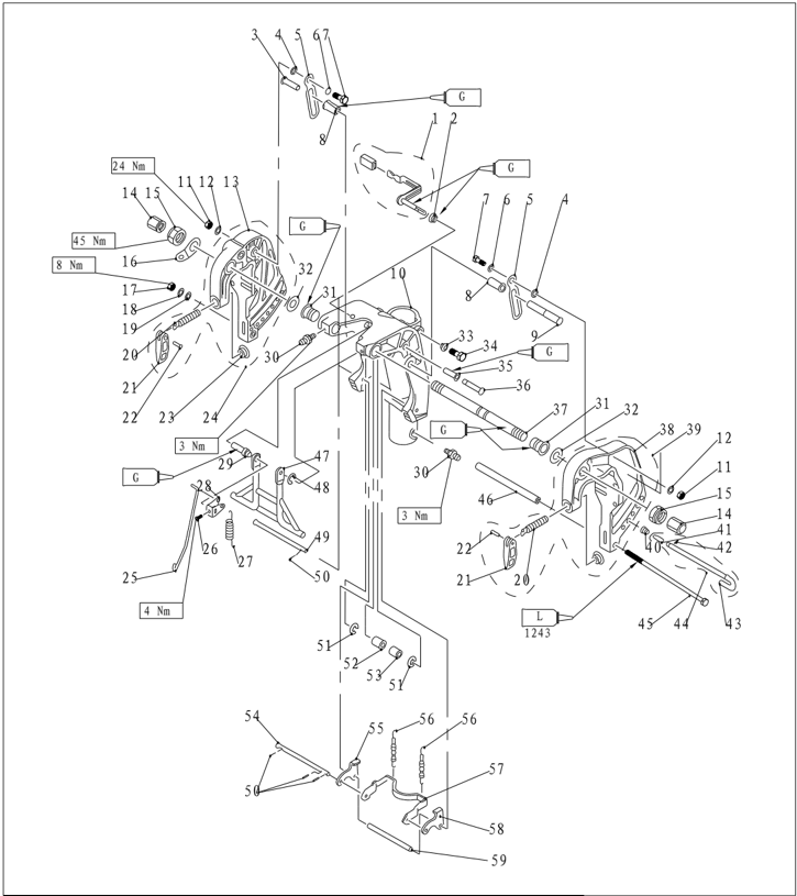
| Číslo dielu | Popis | Popis | ||
|---|---|---|---|---|
| 1 | F25-01010312 | F25-01010312 | F25-01010312 | 1 |
| 2 | F25-01010311 | F25-01010311 | PODLOŽKA | 1 |
| 3 | F25-01010318 | F25-01010318 | ARETAČNÝ KOLÍK (S) | 1 |
| 4 | F25-01010009 | F25-01010009 | Nylonová podložka | 2 |
| 5 | F25-01010321 | F25-01010321 | DOSKA ARETÁCIE NAKLÁPANIA | 2 |
| 6 | F25-01010008 | F25-01010008 | Vlnitá podložka | 2 |
| 7 | F25-01010007 | F25-01010007 | 2 | |
| 8 | F25-01010319 | F25-01010319 | NYLONOVÉ TESNENIE | 2 |
| 9 | F25-01010322 | F25-01010322 | ARETAČNÝ KOLÍK | 1 |
| 10 | F25-01010301 | F25-01010301 | Otočný držiak | 1 |
| F25-01010301S | F25-01010301S | Otočný držiak | 1 | |
| 11 | SAMOISTIACA MATICA M8 GB/T6182-M8 | SAMOISTIACA MATICA M8 GB/T6182-M8 | SAMOISTIACA MATICA M8 GB/T6182-M8 | 2 |
| 12 | 8 F25-01010010 | 8 F25-01010010 | HRUBÁ PODLOŽKA | 2 |
| 13 | F25-01010201 | F25-01010201 | Pravý držiak | 1 |
| 14 | F25-01010011 | F25-01010011 | PLASTOVÁ MATICA | 2 |
| 15 | F15-01010007 | F15-01010007 | 2 | |
| 16 | F25-01010004 | F25-01010004 | DOSKA S DVOMA OTVORMI | 1 |
| 17 | M8 GB/T6170-M8 | M8 GB/T6170-M8 | MATICA M8 | 1 |
| 18 | 8 GB/T93-8 | 8 GB/T93-8 | Pružná podložka 8 | 1 |
| 19 | 8 GB/T97.1-8 | 8 GB/T97.1-8 | PODLOŽKA 8 | 1 |
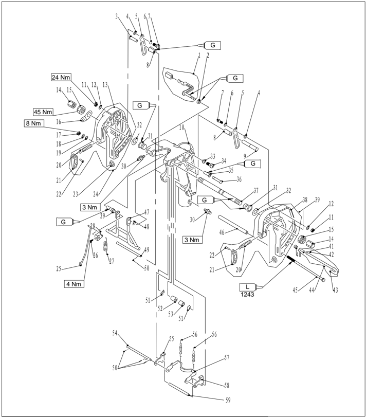
| Číslo dielu | Popis | Poznámky |
|---|---|---|
| F25-01010104 | Upínacia skrutka | |
| F25-01010102 | UPÍNACIA RUKOVÄŤ | |
| F25-01010103 | NIT | |
| F4-01010003 | UPÍNACIA DOSKA | |
| F25-01010200 | ||
| F25-01010315 | TYČ KONZOLY | |
| GB/T818-M5x6 | ||
| F25-01010314 | Ťažná pružina | |
| F25-01010313 | ||
| F25-01010309 | Puzdro rukoväti | |
| GB/T7940.1-M6 | M6 MAZNICA M6 | |
| F25-01010002 | NYLONOVÉ PUZDRO | |
| F25-01010003 | PODLOŽKA | |
| F25-01010302 | TESNIACA PODLOŽKA | |
| F25-01010303 | M8×20 SKRUTKA SO ŠESŤHRANNOU HLAVOU M8x20 | |
| F25-01010317 | KOLÍK PUZDRA | |
| F25-01010316 | ||
| F15-01010001 | ||
| F25-01010101 | ĽAVÁ KONZOLA | |
| F25-01010100 |

| POPIS ČÍSLO DIELU | Poznámky | |
|---|---|---|
| F25-01010403 | Kužeľová pružina | |
| F25-01010402 | ||
| GB/T879.2-3x10 | 3×10 PRUŽNÝ KOLÍK 3x10 | |
| F25-01010401 | ||
| F25-01010400 | ||
| F25-01010005 M8×255 | DLHÁ SKRUTKA M8x255 | |
| F25-01010006 | Rúrka skrutky | |
| F25-01010308 | Zostava podpery | |
| GB/T896-19868 | POISTNÝ KRÚŽOK | |
| F25-01010305 | ||
| φ2x12 GB/T91-2x10 | ZÁVLAČKA Φ2x10 | |
| GB/T896-9 9 | POISTNÝ KRÚŽOK 9 | |
| F25-01010324 TESNENIE | NYLON | |
| F25-01010323 | NYLONOVÁ RÚRKA | |
| F25-01010307-3 | ||
| F25-01010307-4B | ||
| F25-01010304 | Ťažná pružina | |
| F25-01010307-1 | RAMENO ZÁMKU NAKLÁPANIA | |
| F25-01010307-2A | ||
| F25-01010306 |
Demontáž a kontrola
| 1. | Odstráňte dorazovú tyč a skrutku (M6X145). |
|---|---|
| 2 | Odstráňte maticu a skrutku dosky dorazu naklápania a potom dosku. |
| 3 | Odstráňte maticu upínacej konzoly, dosku s dvoma otvormi a obojstrannú závitovú skrutku upínacej konzoly. |
| 4 | Odstráňte upínaciu konzolu. |
| 5 | Odstráňte otočný držiak. |
| 6 | Odstráňte rukoväť zámku uhla a tyč uzamykacej konzoly. Odstráňte ťažnú pružinu a páku nastavenia uhla. |
| 7 | Odstráňte vodiace puzdro a nylonové puzdro. |
| 8 | Odstráňte dlhý a krátky hriadeľ zaistenia uhla. |
| 9 | Odstráňte držiak zaistenia uhla, skrutnú pružinu, ťažnú pružinu a vnútorný držiak. |
| 10 | Skontrolujte poškodenie alebo praskliny otočného a upínacieho držiaka. V prípade potreby ich vymeňte. |
| 11 | Skontrolujte poškodenie alebo praskliny puzdra a tesnenia. V prípade potreby ich vymeňte. |
| 12 | Skontrolujte deformáciu držiaka zaistenia uhla a podporného držiaka. V prípade potreby ich vymeňte. |
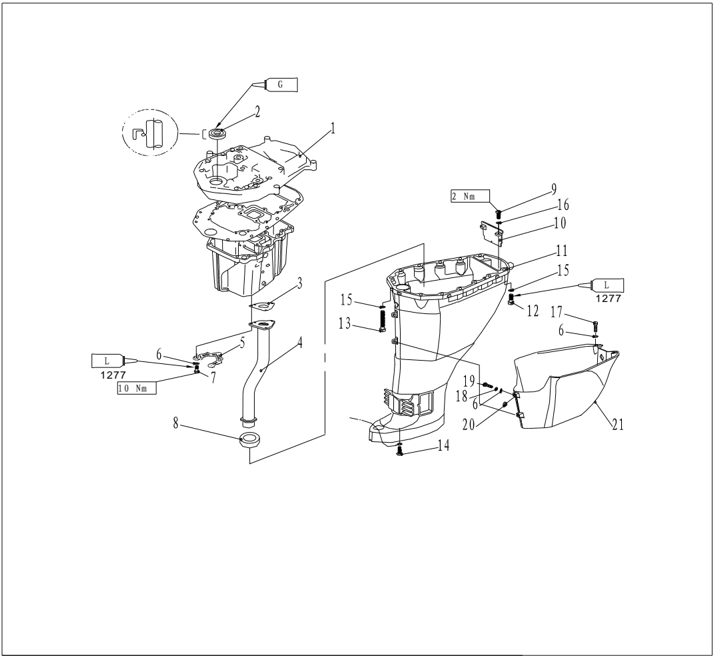
Diely hornej jednotky
Rozložený výkres
| Číslo dielu | Popis | Poznámky | |
|---|---|---|---|
| F25-02010001 | VEDENIE VÝFUKU | ||
| F25-02010002 | Olejové tesnenie | ||
| F25-02000011 | TESNENIE VÝFUKOVEJ RÚRY | ||
| F25-02020000 | ZOSTAVA VÝFUKOVEJ RÚRY | ||
| F25-02020000S | ZOSTAVA VÝFUKOVEJ RÚRY | ||
| V F25-02000012 | V F25-02000012 | DOSKA „V“ | |
| GB/T97.1-6 | 6 | PODLOŽKA 6 | |
| GB/T5782-M6x50 | M6x50 | SKRUTKA M6x50 | |
| F25-02000014 | TESNENIE VÝFUKOVEJ RÚRY | ||
| GB/T818- M5x16 | M5x16 | SKRUTKA S VALCOVOU HLAVOU M5x16 | |
| F25-02000003 | Prepážka výfuku | ||
| F25-02000001 | Horná skriňa | ||
| F25-02000001S | Horná skriňa | ||
| GB/T5783-M8x30 | M8x30 | SKRUTKA M8x30 | |
| GB/T5782-M8x80 | M8x80 | SKRUTKA M8x80 | |
| GB/T818-M6x10 | M6x10 | ||
| GB/T97.1-8 | 8 | PODLOŽKA 8 | |
| GB/T97.1-5 | 5 | PODLOŽKA 5 | |
| GB/T5783-M6x14 | M6x14 | SKRUTKA M6x14 | |
| GB/T93-6 | 6 | Pružná podložka 6 | |
| GB/T818-M6x25 | M6x25 | SKRUTKA S VALCOVOU HLAVOU M6x25 | |
| GB/T6170-M6 | M6 | MATICA M6 | |
| F25-00000200 | Plášť hornej skrine |
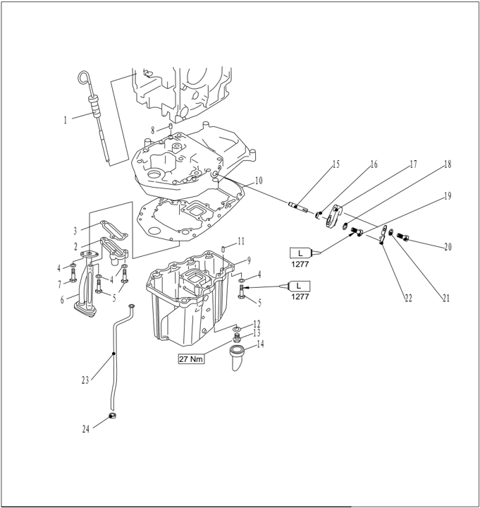
| Číslo dielu | Popis | Popis | Poznámky |
|---|---|---|---|
| F25-00000100 | ZÁTKA KONTROLY HLADINY OLEJA | ||
| F25-02010100 | ZOSTAVA PRETLAKOVÉHO VENTILU | ||
| F25-02010006 | |||
| GB/T97.1-6 | 6 | Plochá podložka 6 | |
| GB/T5783-M6x25 | M6x25 | ||
| F25-02010200 | OLEJOVÉ SITKO | ||
| GB/T5783-M6x16 | M6X16 | ||
| F25-00000014 | 8x12 | Vodiaci kolík | |
| F25-02000006 | OLEJOVÁ VAŇA | ||
| F25-02010007 | SKRUTKA SO ŠESŤHRANNOU HLAVOU | ||
| F15-00000006 | 6x12 | CENTROVACÍ KOLÍK 6x16 | |
| F15-04000003 | TESNENIE | ||
| F15-04000002 | VYPÚŠŤACIA SKRUTKA OLEJA | ||
| F25-02000007 | PUZDRO VÝPUSTU OLEJA | ||
| F25-02010005 | Anóda | ||
| F15-07010009 | TESNENIE ANÓDY | ||
| F15-07010011 | Veko anódy | ||
| GB/T97.1-5 | 5 | PODLOŽKA 5 | |
| GB/T5783-M5x12 | M5x12 | SKRUTKA M5x12 | |
| GB/T5783-M6x20 | M6x20 | SKRUTKA M6x20 | |
| GB/T97.1-6 | 6 | PODLOŽKA 6 | |
| F15-07010012 | Doska anódy | ||
| F25-02000004 | VODNÁ RÚRKA | ||
| F25-02000004S | VODNÁ RÚRKA | ||
| F25-02000005 |
- Vypustite olej.
- Odstráňte upevňovacie skrutky hornej a spodnej jednotky a odstráňte hornú jednotku.
- Odstráňte vodiacu dosku výfuku a olejovú vaňu.
- Z olejovej vane odstráňte výfukovú rúru, skrutku výpustu oleja, puzdro výpustu oleja a tesnenie výfukovej rúry.
- Z vodiacej dosky výfuku odstráňte olejové sitko a zostavu pretlakového ventilu.
- Odstráňte zostavu tlmiča s dvoma otvormi, výfukovú prepážku, gumové tesnenie vodnej rúrky a vodnú rúrku.
- Skontrolujte horný kryt a olejovú vaňu, či nie sú prasknuté alebo opotrebované. V prípade potreby ich vymeňte.
- Skontrolujte deformáciu alebo eróziu vodnej rúrky. V prípade potreby ju vymeňte.
- Skontrolujte zostavu pretlakového ventilu, či nie je prasknutá alebo opotrebovaná. V prípade potreby ju vymeňte.
- Skontrolujte poškodenie, opotrebovanie alebo praskliny prepážky výfuku. V prípade potreby ju vymeňte.
Demontáž a kontrola
Zostava vodného čerpadla
Rozložený výkres
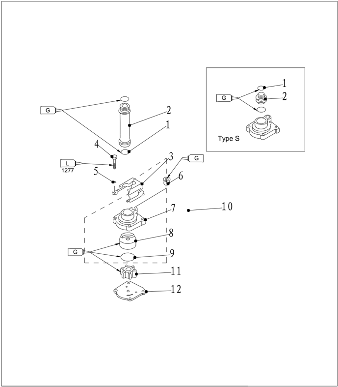
| Číslo dielu | Popis | Popis | ||
|---|---|---|---|---|
| 1 | O25.8x2.65 | O-KRÚŽOK 25.8x2.65 | 2 | |
| 2 | F25-04000017 | Vodná rúrka | 1 | |
| F25-04000017S | Vodná rúrka | 1 | ||
| 3 | F25-04000016 | 1 | ||
| 4 | GB/T5782-M6x40 | M6×40 | SKRUTKA M6x40 | 4 |
| 5 | GB/T97.1-6 | 6 | PODLOŽKA 6 | 4 |
| 6 | F25-04050004 | 1 | ||
| 7 | F25-04050001 | 1 | ||
| 8 | F25-04050002 | VNÚTORNÝ KRYT | 1 | |
| 9 | F25-04050003 | O-KRÚŽOK | 1 | |
| 10 | F25-04050000 | 1 | ||
| 11 | F25-04040000 | ZOSTAVA OBEŽNÉHO KOLESA | 1 | |
| 12 | F25-04000014 | Vonkajšia doska | 1 |
Demontáž a kontrola
- Odstráňte upevňovaciu dosku vodného čerpadla.
- Odstráňte kryt vodného čerpadla.
- Odstráňte obežné koleso a vnútornú skriňu vodného čerpadla.
- Odstráňte polkruhové pero a vonkajšiu dosku.
.
- Skontrolujte kryt vodného čerpadla a vonkajšiu dosku, či nie sú prasknuté, zdeformované alebo poškodené. V prípade potreby ich vymeňte.
- Skontrolujte vnútorný kryt vodného čerpadla a obežné koleso, či nie sú prasknuté, zdeformované, spálené alebo opotrebované. V prípade potreby ich vymeňte.
Spodná jednotka
Ozubené kolesá spodnej jednotky
Rozložený výkres
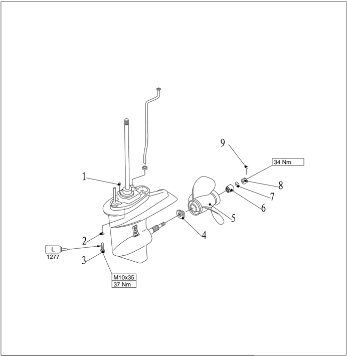
| Číslo dielu | Popis | Popis | Poznámky | |
|---|---|---|---|---|
| 1 | F15-00000006 | φ6x12 | Vodiaci kolík | |
| 2 | GB/T97.1-10 | 10 | PODLOŽKA 10 | |
| 3 | F25-00000011 | SKRUTKA M10x1.25x35 | ||
| 4 | F25-04000024 | |||
| 5 | F25-04080000 | ZOSTAVA VRTULE | ||
| 6 | F25-04000025 | DIŠTANČNÝ KRÚŽOK | ||
| 7 | GB/T97.1-14 | 14 | PODLOŽKA 14 | |
| 8 | F25-04000027 | Matica | ||
| 9 | GB/T91-2.5x22φ2.5x22 |
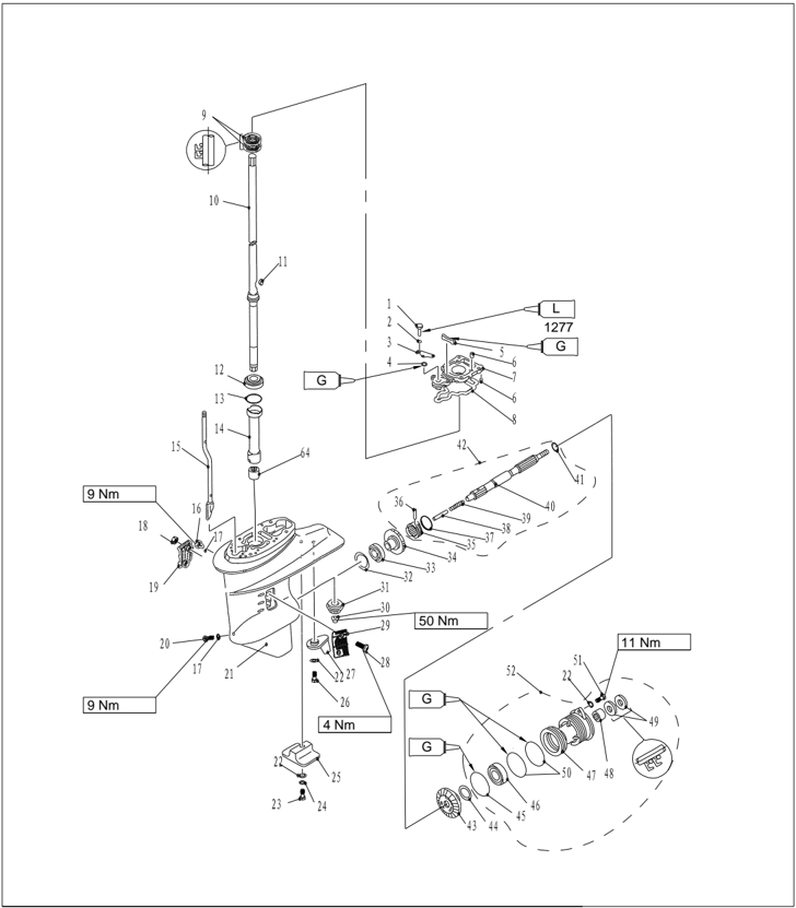
| Číslo dielu | Popis | Popis | Poznámky |
|---|---|---|---|
| B/T5783-M6×25 | M6×25 | Skrutka M6×25 | |
| GB/T97.1-6 | 6 | PODLOŽKA 6 | |
| F25-04000012O | DOSKA O-KRÚŽKU | ||
| F15-06020004 | O | O-krúžok | |
| F25-04000013 | VODNÉ TESNENIE | ||
| F25-04000007 | Φ4x10 | CENTROVACÍ KOLÍK 4x10 | |
| F25-04000008 | Základňa hnacieho hriadeľa | ||
| F25-04000009 | Tesnenie | ||
| F25-04010003 | 22x36x6 | ||
| F25-04010000 | Zostava hnacieho hriadeľa | ||
| F25-04010000S | Zostava hnacieho hriadeľa | ||
| F25-04000015 | POLKRUHOVÉ PERO | ||
| TELESO LOŽISKA | |||
| F25-04000003-1 | VYMEDZOVACIA PODLOŽKA(t:0.7mm) | ||
| F25-04000003-2 | VYMEDZOVACIA PODLOŽKA(t:1.0mm) |
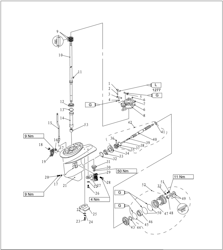
| Číslo dielu | Popis | |||
|---|---|---|---|---|
| F25-04000003-3 | VYMEDZOVACIA PODLOŽKA(t:1.1mm) | |||
| F25-04000003-4 | VYMEDZOVACIA PODLOŽKA(t:1.2mm) | |||
| F25-04000003-5 | VYMEDZOVACIA PODLOŽKA(t:1.3mm) | |||
| F25-04000003-6 | VYMEDZOVACIA PODLOŽKA(t:1.4mm) | |||
| F25-04000003-7 | VYMEDZOVACIA PODLOŽKA(t:1.5mm) | |||
| F25-04000003-8 | VYMEDZOVACIA PODLOŽKA(t:1.6mm) | |||
| 14 | F25-04000002 | Nylonové puzdro | 1 | |
| 15 | F25-04030000 | 1 | ||
| F25-04030000S | 1 | |||
| 16 | F4-03000023 | ZÁTKA OLEJOVÉHO OTVORU | 1 | |
| 17 | F4-03000024 | TESNENIE | 2 | |
| 18 | GB/T889.1-M5 | POISTNÁ MATICA M5 | 2 | |
| 19 | F25-04000023 | B | Vstup vody B | 1 |
| 20 | F25-04000031 | VYPÚŠŤACIA ZÁTKA | 1 | |
| 21 | F25-04000001 | SPODNÁ SKRIŇA | 1 | |
| 22 | GB/T97.1-6 | 6 | PODLOŽKA 6 | 4 |
| 23 | GB/T5782-M6x35 | M6×35 | Skrutka M6×35 | 1 |
| 24 | GB/T861.1-6 | 6 | Poistná podložka 6 | 1 |
| 25 | F15-06000004 | DOLNÁ ANÓDA | 1 | |
| 26 | GB/T5783-M6x20 | M6×20 | Skrutka M6×35 | 1 |
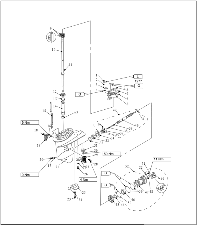
| Číslo dielu | Popis | Popis | Poznámky | ||
|---|---|---|---|---|---|
| 27 | F25-04000021 | SMEROVÁ PLUTVIČKA | 1 | ||
| 28 | GB/T820-M5x30 | 1 | |||
| 29 | F25-04000022 | A | Vstup vody A | 1 | |
| 30 | F25-04000006 | MATICA PASTORKA | 1 | ||
| 31 | F25-04000005 | Pastorok | 1 | ||
| 32 | F25-04000004-1 | VYMEDZOVACIA PODLOŽKA(t:1.0mm) | |||
| F25-04000004-2 | VYMEDZOVACIA PODLOŽKA(t:1.1mm) | ||||
| F25-04000004-3 | VYMEDZOVACIA PODLOŽKA(t:1.2mm) | ||||
| F25-04000004-4 | VYMEDZOVACIA PODLOŽKA(t:1.3mm) | ||||
| F25-04000004-5 | VYMEDZOVACIA PODLOŽKA(t:1.4mm) | ||||
| 33 | 1 | ||||
| 34 | F25-04020000 | KOLESO DOPREDNÉHO CHODU | 1 | ||
| 35 | F25-04060003 | Zubová spojka | 1 | ||
| 36 | F15-06070004 | Čap spojky | 1 | ||
| 37 | F15-06070005 | Krúžok spojky | 1 | ||
| 38 | F25-04060006 | Radiaci piestik | 1 | ||
| 39 | F25-04060002 | Pružina spojky | 1 | ||
| 40 | F25-04060001 | HRIADEĽ VRTULE | 1 | ||
| 41 | F25-04060007 | 1 | |||
| 42 | F25-04060000 | 1 |
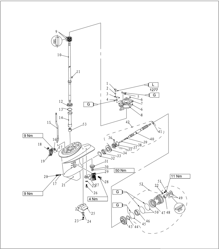
| Číslo dielu | Popis | Poznámky | ||
|---|---|---|---|---|
| 43 | F25-04070004 | KOLESO SPÄTNÉHO CHODU | 1 | |
| 44 | F25-04070005-1 | VYMEDZOVACIA PODLOŽKA(t:1.0mm) | ||
| F25-04070005-2 | VYMEDZOVACIA PODLOŽKA(t:1.1mm) | |||
| F25-04070005-3 | VYMEDZOVACIA PODLOŽKA(t:1.2mm) | |||
| F25-04070005-4 | VYMEDZOVACIA PODLOŽKA(t:1.3mm) | |||
| 45 | F25-04070002 | O-KRÚŽOK A | 1 | |
| 46 | KOYO 6006C3 | GUĽÔČKOVÉ LOŽISKO | 1 | |
| 47 | F25-04070001 | 26x20x16 VALČEKOVÉ LOŽISKO | 1 | |
| 48 | 20x34x6.5 OLEJOVÉ TESNENIE 20x34x6.5 | 1 | ||
| 49 | F25-04070006 | 2 | ||
| 50 | F25-04070003 | O-KRÚŽOK B | 2 | |
| GB/T5783-M6x20 | SKRUTKA M6x20 M6x20 | 2 | ||
| 52 | F25-04070000 | 1 | ||
| 53 | F2020 | IHLOVÉ LOŽISKO | 1 |
Demontáž a kontrola
- Vypustite olej a vyberte závlačku.
- Medzi lodnú skrutku a antikavitačnú dosku vložte kus dreva. Odstráňte šesťhrannú maticu, anódu a vstup vody.
- Odstráňte zostavu lodnej skrutky a tlmiacu podložku.
- Odstráňte anódu.
- Odstráňte veko spodnej skrine. Odstráňte koleso spätného chodu a vymedzovaciu podložku. Odstráňte olejové tesnenie.
- Odstráňte zostavu hriadeľa lodnej skrutky.
- Odstráňte radiaci piestik.
- Odstráňte krúžok spojky, čap a zubovú spojku. Odstráňte pružinu spojky.
- Odstráňte základňu hnacieho hriadeľa.
- Kľúčom s vnútorným drážkovaním odstráňte maticu pastorka. Vyberte hnací hriadeľ a jeho nylonové puzdro.
- Vyberte zostavu vačky radiacej tyče a koleso dopredného chodu.
- Odstráňte ihlové ložisko zo spodnej jednotky.
- Vyberte olejové tesnenie zo základne hnacieho hriadeľa a ložisko z kolesa dopredného chodu.
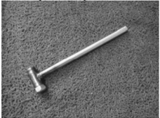
Hriadeľ vrtule a spojkový blok
- Skontrolujte praskliny alebo poškodenie zubovej spojky. V prípade potreby ju vymeňte.
- Skontrolujte opotrebovanie alebo ohnutie hriadeľa lodnej skrutky. V prípade potreby ho vymeňte.
- Skontrolujte hádzavosť hriadeľa lodnej skrutky. Ak nezodpovedá špecifikácii, vymeňte ho.
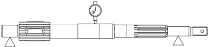
: 0.02 mm
Montáž zubovej spojky
- Vložte pružinu spojky do otvoru na konci hriadeľa lodnej skrutky.
Medzná hádzavosť
- Namontujte zubovú spojku podľa obrázka. Uistite sa, že značka 'F' alebo '●' smeruje ku kolesu dopredného chodu. Namontujte kolík spojky.
- Namontujte krúžok spojky a radiaci piestik.
- Namontujte olejové tesnenie.
- Namontujte nové ložisko na koleso spätného chodu.

Poznámka:
Namontujte olejové tesnenie a ložisko pomocou špeciálneho náradia.
Pri montáži venujte pozornosť smeru a hĺbke.
Uistite sa, že značka výrobcu ložiska smeruje ku kolesu spätného chodu.
Montážna hĺbka:
Prípravok na montáž ložiska krytu spodnej skrine
| Ihlové ložisko | Ihlové ložisko | 31.0~31.5mm |
|---|---|---|
| Hĺbka1 | 13.0~13.5mm | |
| Hĺbka2 | 6.0~6.5mm |
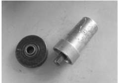
Prípravok na montáž olejového tesnenia veka spodnej skrine
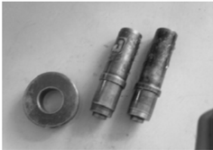
Kryt spodnej skrine
- Skontrolujte ložisko na hrdzu alebo dunenie pri chode. V prípade potreby ho vymeňte.
- Pomocou sťahováka ložísk odstráňte ložisko a olejové tesnenie.
Poznámka:
Ložisko neodstraňujte, ak ho nebudete meniť.
- Pomocou špeciálneho náradia odstráňte ihlové ložisko.
Poznámka:
Pri opätovnej montáži olejového tesnenia a ihlového ložiska použite nové diely.
- Mäkkou kefkou a rozpúšťadlom vyčistite kryt skrine.
- Skontrolujte kryt skrine na praskliny alebo poškodenie. V prípade potreby ho vymeňte.
Montáž olejového tesnenia a ložiska krytu spodnej skrine
Montážny prípravok ihlového ložiska veka spodnej skrine
- Namontujte ozubené koleso chodu vzad a podložku.
Poznámka:
Pri montáži nového kolesa spätného chodu a ložiska upravte vymedzovacie podložky.
Hnací hriadeľ
- Skontrolujte hnací hriadeľ na deformáciu alebo opotrebenie. V prípade potreby ho vymeňte.
- Skontrolujte hádzavosť hnacieho hriadeľa.

Limit hádzavosti: 0.05 mm
Montážny prípravok ložiska kolesa spätného chodu
Vačka radiacej tyče
Skontrolujte opotrebovanie alebo deformáciu vačky radiacej tyče. V prípade potreby ju vymeňte.
Ozubené koleso
Skontrolujte opotrebovanie alebo poškodenie kolesa chodu vpred, kolesa spätného chodu a pastorka. V prípade potreby ich vymeňte.
Ložisko prevodu vpred
Skontrolujte hrdzu alebo dunenie ložiska pri otáčaní. V prípade potreby ho vymeňte.
Poznámka:
Ložisko nevyberajte, ak ho nebudete meniť.
Pri montáži nového ložiska nastavte vymedzovaciu podložku.
Kontrola spodnej skrine
Skontrolujte praskliny alebo poškodenie spodnej skrine a upchatie vstupu chladiacej vody. V prípade potreby vymeňte.
Montáž spodnej skrine
- Pomocou špeciálneho náradia namontujte ihlové ložisko.
Prípravok na montáž ihlového ložiska
- Namontujte nové ložisko kolesa dopredného chodu (ak ho meníte).
- Namontujte olejové tesnenie základne hnacieho hriadeľa.
- Namontujte nylonové puzdro, zostavu vačky radiacej tyče, tesnenie a základňu hnacieho hriadeľa. Namontujte koleso dopredného chodu, hnací hriadeľ, vymedzovaciu podložku a pastorok.
Nástroj na montáž skrine ložiska ozubeného kolesa chodu vpred
Montážny prípravok olejového tesnenia hnacieho hriadeľa
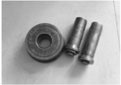
UPOZORNENIE:
Pri montáži novej základne hnacieho hriadeľa alebo nového hnacieho hriadeľa upravte vymedzovaciu podložku.
- Utiahnite maticu pastorka. Predpísaný moment: 50Nm
- Namontujte zostavu hriadeľa lodnej skrutky.
- Namontujte veko spodnej skrine.
- Skontrolujte správnu funkciu radenia.
Montážny prípravok veka spodnej skrine
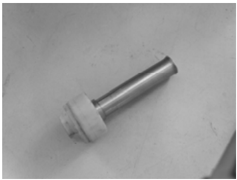
- Namontujte zostavu vodného čerpadla.
- Namontujte anódu a vstup vody.
- Namontujte lodnú skrutku a šesťhrannú maticu. Medzi lodnú skrutku a antikavitačnú dosku vložte kus dreva. Utiahnite maticu predpísaným momentom.
Predpísaný moment: 34Nm
Poznámka:
Ak drážka matice nie je zarovnaná s otvorom závlačky hriadeľa lodnej skrutky, utiahnite maticu až do zarovnania.
Inštalácia spodnej jednotky
- Namontujte vodiaci kolík.
- Presuňte zostavu vačky radiacej tyče do polohy spätného chodu. Namontujte spodnú jednotku k hornej skrini a utiahnite skrutky predpísaným momentom. Predpísaný moment: 37 Nm
- Spojte valcovú maticu a zostavu vačky radiacej tyče. Preraďte a skontrolujte správnu funkciu. V prípade potreby upravte polohu valcovej matice. Maticu dôkladne utiahnite.
- Pomocou tlakového plniaceho zariadenia doplňte prevodový olej.
Výber vymedzovacích podložiek
Pri výmene dielov v spodnej jednotke alebo montáži novej spodnej jednotky upravte vymedzovaciu podložku.
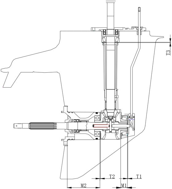
Podložka pastorka
- Namontujte hnací hriadeľ na špeciálny prípravok. Namontujte pastorok a utiahnite ho predpísaným momentom. Predpísaný moment: 50 Nm
- Škáromerom zmerajte vôľu medzi špeciálnym prípravkom a pastorkom a vypočítajte hrúbku T3 podľa vzorca. Výpočtový vzorec: T3=M3
- Vyberte vymedzovaciu podložku podľa nasledujúcej tabuľky.
| T3 | T3 | Výber rozmeru vymedzovacej podložky |
|---|---|---|
| Od | Do | Výber rozmeru vymedzovacej podložky |
| 1.10 | 1.20 | 1.2 |
| 1.20 | 1.30 | 1.3 |
| 1.30 | 1.40 | 1.4 |
| 1.40 | 1.50 | 1.5 |
| 1.50 | 1.60 | 1.6 |
| 1.60 | 1.70 | 0.7+1.0 |
| 1.70 | 1.83 | 0.7+1.1 |
| Voliteľné rozmery vymedzovacej podložky: 0.7, 1.0, 1.1, 1.2, 1.3, 1.4, 1.5, 1.6 | Voliteľné rozmery vymedzovacej podložky: 0.7, 1.0, 1.1, 1.2, 1.3, 1.4, 1.5, 1.6 | Voliteľné rozmery vymedzovacej podložky: 0.7, 1.0, 1.1, 1.2, 1.3, 1.4, 1.5, 1.6 |
Jednotka: mm
Podložka ozubeného kolesa chodu vpred
- Otáčajte vonkajším krúžkom kolesa dopredného chodu, aby valček úplne dosadol do ložiskového telesa.
- Zmerajte výšku ložiska a vypočítajte hrúbku T1 podľa vzorca. Výpočtový vzorec: T1=17.5-M3
Poznámka:
Hrúbku zmerajte v troch meracích bodoch.
Použite priemernú hodnotu.
- Vyberte vymedzovaciu podložku podľa nasledujúcej tabuľky.
| T1 | T1 | Výber rozmeru vymedzovacej podložky |
|---|---|---|
| Od | Do | Výber rozmeru vymedzovacej podložky |
| 0.99 | 1.10 | 1.0 |
| 1.10 | 1.20 | 1.1 |
| 1.20 | 1.30 | 1.2 |
| 1.30 | 1.40 | 1.3 |
| 1.40 | 1.50 | 1.4 |
| Voliteľné rozmery vymedzovacej podložky: 1.0, 1.1, 1.2, 1.3, 1.4 | Voliteľné rozmery vymedzovacej podložky: 1.0, 1.1, 1.2, 1.3, 1.4 |
Jednotka: mm
- Špeciálny nástroj
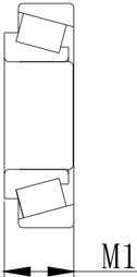
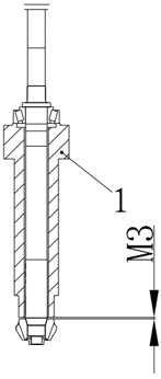
Podložka ozubeného kolesa chodu vzad
- Zmerajte rozmer podľa nasledujúceho obrázka.
- Vypočítajte hrúbku T2 podľa vzorca.
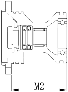
Výpočtový vzorec: T2=80-M2
- Vyberte vymedzovaciu podložku podľa nasledujúcej tabuľky.
| T2 | T2 | Výber rozmeru vymedzovacej podložky |
|---|---|---|
| Od | Do | Výber rozmeru vymedzovacej podložky |
| 0.99 | 1.10 | 1.0 |
| 1.10 | 1.20 | 1.1 |
| 1.20 | 1.30 | 1.2 |
| 1.30 | 1.32 | 1.3 |
| Voliteľné rozmery vymedzovacej podložky: 1.0, 1.1, 1.2, 1.3 | Voliteľné rozmery vymedzovacej podložky: 1.0, 1.1, 1.2, 1.3 |
Jednotka: mm
Bežné problémy a ich riešenia
| Typ problému | Možná príčina | Nápravné opatrenie |
|---|---|---|
| Štartér nefunguje | Súčasti štartéra sú chybné | Opravte alebo vymeňte |
| Štartér nefunguje | Radiaca páka nie je v neutrálnej polohe | Presuňte do neutrálnej polohy |
| Motor neštartuje | Palivová nádrž je prázdna | Naplňte nádrž čistým čerstvým palivom |
| Motor neštartuje | Palivo je znečistené alebo staré | |
| Motor neštartuje | Palivový filter je upchatý | Vymeňte palivový filter |
| Motor neštartuje | Palivové čerpadlo je chybné | Skontrolujte alebo vymeňte |
| Motor neštartuje | Odvzdušňovacia skrutka palivovej nádrže nie je povolená | Uvoľnite odvzdušňovaciu skrutku |
| Motor neštartuje | Zapaľovacie sviečky sú znečistené alebo nesprávneho typu. | Skontrolujte zapaľovacie sviečky. Vyčistite ich alebo vymeňte za odporúčaný typ |
| Motor neštartuje | Koncovky sviečok sú nesprávne nasadené | Skontrolujte a znovu nasaďte koncovky |
| Motor neštartuje | Vedenie zapaľovania je chybné | Skontrolujte vodiče. Utiahnite všetky uvoľnené spoje. Vymeňte opotrebované alebo poškodené vodiče |
| Motor neštartuje | Diely zapaľovania sú chybné | Vymeňte |
| Motor neštartuje | Núdzové vypínacie lanko nie je pripojené | Pripojte núdzové vypínacie lanko |
| Motor neštartuje | Vnútorné diely motora sú poškodené | Opravte |
| Motor beží nepravidelne na voľnobeh alebo sa zastaví | Zapaľovacie sviečky sú znečistené alebo nesprávneho typu. | Skontrolujte zapaľovacie sviečky. Vyčistite ich alebo vymeňte za odporúčaný typ |
| Motor beží nepravidelne na voľnobeh alebo sa zastaví | Palivový systém je upchatý | Skontrolujte privretú alebo zalomenú palivovú hadicu a iné prekážky v palivovom systéme |
| Motor beží nepravidelne na voľnobeh alebo sa zastaví | Palivo je znečistené alebo staré | Naplňte nádrž čistým čerstvým palivom |
| Motor beží nepravidelne na voľnobeh alebo sa zastaví | Palivový filter je upchatý | Vymeňte |
| Motor beží nepravidelne na voľnobeh alebo sa zastaví | Vzdialenosť elektród sviečky je nesprávna | Skontrolujte a nastavte podľa predpisu |
| Motor beží nepravidelne na voľnobeh alebo sa zastaví | Vedenie zapaľovania je chybné | Skontrolujte vodiče. Utiahnite všetky uvoľnené spoje. Vymeňte opotrebované alebo poškodené vodiče |
| Motor beží nepravidelne na voľnobeh alebo sa zastaví | Nepoužíva sa predpísaný motorový olej | Skontrolujte a vymeňte olej podľa predpisu |
| Motor beží nepravidelne na voľnobeh alebo sa zastaví | Termostat je chybný | Vymeňte |
| Motor beží nepravidelne na voľnobeh alebo sa zastaví | Karburátor je chybný | Vymeňte |
| Motor beží nepravidelne na voľnobeh alebo sa zastaví | Palivové čerpadlo je chybné | Vymeňte |
| Motor beží nepravidelne na voľnobeh alebo sa zastaví | Odvzdušňovacia skrutka palivovej nádrže nie je povolená | Uvoľnite odvzdušňovaciu skrutku |
| Motor beží nepravidelne na voľnobeh alebo sa zastaví | Gombík sýtiča je vytiahnutý | Vráťte sa domov |
| Motor beží nepravidelne na voľnobeh alebo sa zastaví | Poloha | |
| Motor beží nepravidelne na voľnobeh alebo sa zastaví | Uhol motora je príliš veľký | Vráťte do normálnej prevádzkovej polohy |
| Strata výkonu motora | Vrtuľa je poškodená | Opravte alebo vymeňte vrtuľu |
| Strata výkonu motora | Trimovací uhol je nesprávny | Nastavte uhol trimu na najúčinnejšiu hodnotu |
| Strata výkonu motora | Motor je namontovaný v nesprávnej výške na priečniku | Nastavte správnu montážnu výšku motora na zrkadle |
| Strata výkonu motora | Dno člna je znečistené vodnými organizmami | Vyčistite dno člna |
| Strata výkonu motora | Vodné rastliny alebo iné cudzie predmety sú zachytené na prevodovej skrini | Odstráňte cudzie predmety a vyčistite spodnú jednotku |
| Strata výkonu motora | Zapaľovacie sviečky sú znečistené alebo nesprávneho typu. | Skontrolujte zapaľovacie sviečky. Vyčistite ich alebo vymeňte za odporúčaný typ |
| Strata výkonu motora | Palivový systém je upchatý | Skontrolujte privretú alebo zalomenú palivovú hadicu a iné prekážky v palivovom systéme |
| Strata výkonu motora | Palivový filter je upchatý | Vymeňte palivový filter |
| Strata výkonu motora | Palivo je znečistené alebo staré | Naplňte nádrž čistým čerstvým palivom |
| Strata výkonu motora | Vzdialenosť elektród sviečky je nesprávna | Skontrolujte a nastavte podľa predpisu |
| Strata výkonu motora | Vedenie zapaľovania je chybné | Skontrolujte vodiče. Utiahnite všetky uvoľnené spoje. Vymeňte opotrebované alebo poškodené vodiče |
| Strata výkonu motora | Diely zapaľovania zlyhali | Vymeňte |
| Strata výkonu motora | Nepoužíva sa predpísaný motorový olej alebo je ho naplneného príliš veľa | Skontrolujte a vymeňte olej podľa predpisu alebo upravte hladinu motorového oleja na predpísanú úroveň |
| Strata výkonu motora | Termostat je chybný | Vymeňte |
| Strata výkonu motora | Palivové čerpadlo je chybné | Vymeňte |
| Strata výkonu motora | Palivová prípojka je nesprávne pripojená | Správne pripojte |
| Strata výkonu motora | Nepoužívajú sa predpísané zapaľovacie sviečky | Skontrolujte a vymeňte zapaľovacie sviečky podľa špecifikácie |
| Motor nadmerne vibruje | Vrtuľa je poškodená | Opravte alebo vymeňte vrtuľu |
| Motor nadmerne vibruje | Hriadeľ vrtule je poškodený | Vymeňte |
| Motor nadmerne vibruje | Vodné rastliny alebo iné cudzie predmety sú zachytené na vrtuli | Demontujte a vyčistite vrtuľu |
| Motor nadmerne vibruje | Montážna skrutka motora je uvoľnená | Utiahnite skrutku |
| Motor nadmerne vibruje | Otočný čap riadenia je uvoľnený | Utiahnite otočný čap riadenia |
| Motor nadmerne vibruje | Čap riadenia je poškodený | Vymeňte |