
Parsun F2.6 külmotor szervizkézikönyv
Tartalomjegyzék
FIGYELMEZTETÉS:
Általános információk
Azonosítás
A külmotor gyári száma a címkén található. A címke a tartókonzol bal oldali egységén vagy a forgókonzol felső részén található. Jegyezze fel a külmotor gyári számát a kijelölt helyekre, hogy megkönnyítse az alkatrészrendelést Parsun kereskedőjénél. A lopások megelőzése érdekében a gyáriszám-címke megsemmisül, ha eltávolítják a külmotorról.

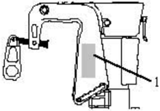
- 1.A külmotor gyári számának helye. A gyári szám felépítése:
GYÁRTÁSI KÓD

Hajócsavar kiválasztása
A hajócsavar kiválasztása döntően befolyásolja a külmotor teljesítményét, mert a helytelen választás ronthatja azt.
Nagyobb hajóterhelés és alacsony motorfordulatszám esetén kisebb emelkedésű hajócsavar alkalmasabb. A megfelelő motorfordulatszám fenntartandó.
Teljes gázas üzemnél a teljesítménynek megfelelő hajócsavart kell használni.
| Hajócsavar méretei | Anyag |
|---|---|
| 71/4×6 | Alumíniumötvözet |
| 71/4×51/2 | Alumíniumötvözet |
| 71/4×71/4 | Alumíniumötvözet |
| 71/4×81/4 | Alumíniumötvözet |
| 71/2×51/2 | Alumíniumötvözet |
Vészindítás
Ha az indítóberendezés nem működik, a motor vészindító kötéllel indítható.
- Vészindító kötél használatakor győződjön meg arról, hogy a váltórúd NEUTRAL (üres) helyzetben van.
- Tartsa távol a tárgyakat. Ne érintse meg a lendkereket vagy más mozgó alkatrészt.
- Indítás és üzemeltetés közben ne érintse meg a gyújtótekercset, a gyertyapipát vagy más elektromos alkatrészt.
Az eljárás a következő:
- 1.Távolítsa el a felső motorburkolatot.
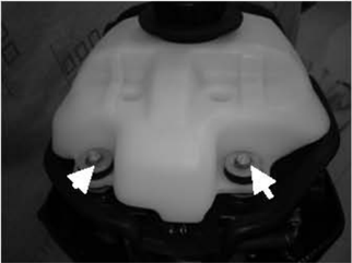
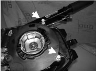
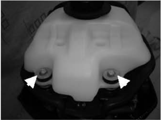
- Távolítsa el az üzemanyagtartály rögzítőcsavarjait.
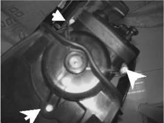
- 3.Emelje fel az üzemanyagtartályt, és távolítson el három csavart.
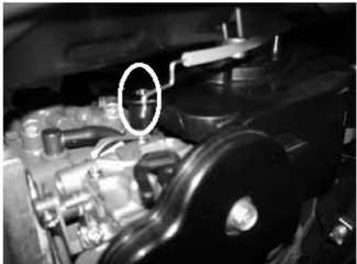
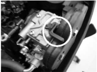
- 4.Emelje fel az indítót, és válassza le a szívatóbowdent a karburátorról.
- 5.Távolítsa el az indítót.
- Szerelje be a lendkerékburkolat rögzítőcsavarjait.
- 7.Szerelje be az üzemanyagtartály rögzítőcsavarjait.
- 8.Hideg motornál fordítsa el a karburátor karját a szívatórendszer működtetéséhez. A motor beindulása után állítsa vissza a kart alaphelyzetbe.
- 9.Illessze a kötél csomóját a lendkerék forgórészének hornyába, és tekerje a kötelet több fordulattal a lendkerék köré az óramutató járásával megegyező irányban.
- Lassan húzza az indítófogantyút, amíg ellenállást nem érez.
- Erős rántással indítsa be a motort. Szükség esetén ismételje meg.
Biztonság munkavégzés közben
A karbantartás és javítás során felmerülő veszélyek és balesetek megelőzése, valamint a hatékony munkavégzés érdekében tartsa be az alábbi biztonsági eljárásokat.
1. Tűzmegelőzés
A benzin, a kenőolaj és a kenőzsír rendkívül gyúlékony. Munkavégzés közben tartsa távol a hőtől, szikráktól és nyílt lángtól.
2. Szellőzés
Nagy mennyiségben belélegezve halálos is lehet. Beltéri próbaüzem során biztosítson megfelelő szellőzést.
3. Személyi védelem
Fúráskor, csiszoláskor vagy légkompresszor használatakor viseljen megfelelő védőszemüveget. Kezét és lábát szükség szerint védőruházattal, védőkesztyűvel és védőcipővel óvja.
4. Kenőanyagok és tömítőfolyadékok
A Parsun külmotorok karbantartásához és javításához kizárólag a vállalatunk által biztosított vagy ajánlott termékeket használja.
Normál használati körülmények között az itt említett kenőanyagok használata nem járhat veszéllyel, de a biztonság elsődleges; megfelelő munkavégzési szokásokkal minden kockázat minimálisra csökkenthető.
A legfontosabb óvintézkedések:
- ① A bőr védelmére munkakezdés előtt megfelelő bőrvédő krém használata ajánlott a kézen.
- ? A kenőanyaggal szennyezett ruházatot a lehető leghamarabb cserélje le, és újbóli használat előtt mossa ki.
- ③ Kerülje a kenőanyagok bőrrel való érintkezését.
- @ A kenőanyaggal vagy kenőanyaggal szennyezett ruhával érintkező kezet és egyéb testrészeket a lehető leghamarabb alaposan mossa meg meleg vízzel és szappannal.
- Legyen kéznél tiszta, szöszmentes törlőruha a kifolyt olaj vagy zsír letörléséhez.
5. Helyes munkavégzési gyakorlat
- ① Tartsa be a meghúzási nyomatékra vonatkozó előírást. A csavarok és anyák közül először a nagyobb méretűeket húzza meg, a belső helyzetű rögzítőket pedig a külsők előtt.
- Q Az alkatrészek sérülésének elkerülésére használja az ajánlott célszerszámokat. A megfelelő szerszámot megfelelő módon használja.
Szétszerelés és összeszerelés
Szétszereléskor és összeszereléskor tartsa be az alábbi alapelveket:
- Használjon célszerszámokat a szét- és összeszereléshez.
- 2.Szétszerelés előtt tisztítsa le a szennyeződést az alkatrészekről.
- 3.Összeszerelés előtt olajozza meg a mozgó alkatrészek érintkező felületeit.
- 4.A csapágyat úgy szerelje be, hogy a gyártói jelölések láthatók legyenek, és bőségesen olajozza meg.
- Az olajtömítések beszerelésekor vékonyan kenje be vízálló zsírral a peremet és a külső átmérőt.
- 6.Összeszerelés után ellenőrizze a mozgó alkatrészek megfelelő működését.
Egyszer használatos alkatrészek
Egyszer használatos alkatrészek a tömítések, olajtömítések, O-gyűrűk, sasszegek, rugók, gyűrűk stb. A külmotor újbóli összeszerelésekor ezeket ki kell cserélni.
Átadás előtti ellenőrzés
A megfelelő használat biztosításához átadás előtt ellenőrizze az alábbiakat.
1. Üzemanyagrendszer ellenőrzése
Ellenőrizze az üzemanyagcső csatlakozásának szorosságát és az üzemanyagtartály feltöltöttségét.
VIGYÁZAT:
Ehhez a 4 ütemű külmotorhoz ne használjon előre kevert üzemanyagot.
2. Olajszint ellenőrzése
Motorolajszint ellenőrzése
Ellenőrizze a motorolaj szintjét az olajszint-ellenőrző nyílásnál.
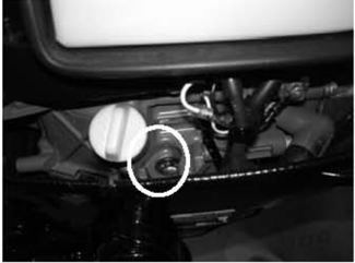
- Felső szintjelölés 2. Alsó szintjelölés
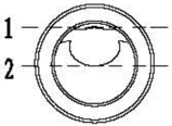
Győződjön meg arról, hogy az olajszint az alsó és felső jelölés között van. A felső jelölés felett eresszen le motorolajat; az alsó jelölés alatt töltsön utána a felső jelölésig.
Hajtóműolajszint ellenőrzése
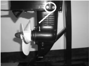
Távolítsa el az olajszintcsavart. Ellenőrizze, hogy a hajtóműolaj kifolyik-e az olajszint-ellenőrző nyíláson. Ha igen, szerelje be az olajszintcsavart, és húzza meg az előírt nyomatékkal.
Ellenkező esetben töltsön utána hajtóműolajat.
- Olajszintcsavar
3. Kormányrendszer ellenőrzése
Ellenőrizze a kormányzás stabilitását.
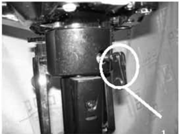
Ellenőrizze a kormányzás súrlódásának megfelelő beállítását. Az ellenállás növeléséhez fordítsa a szorítófogantyú csavarját az óramutató járásával megegyező irányba.
Az ellenállás csökkentéséhez fordítsa a szorítófogantyú csavarját az óramutató járásával ellentétes irányba.
4. Váltókar és gázkar ellenőrzése
Ellenőrizze, hogy a váltókar akadálytalanul működik-e.
Ellenőrizze, hogy a gázmarkolat teljesen zárt helyzetből teljesen nyitott helyzetbe akadálytalanul fordítható-e.
5. Motorleállító kapcsolóegység ellenőrzése
Ellenőrizze, hogy a motor leáll-e a motorleállító kapcsoló megnyomásakor vagy a biztonsági zsinór kihúzásakor.
6. Hűtővíz ellenőrző nyílásának ellenőrzése
Működő motornál ellenőrizze, hogy
- Szorítófogantyú csavarja
folyik-e hűtővíz a hűtővíz ellenőrző nyílásából.
7. Bejáratás
- Első 1 óra: járassa a motort 2000 r/min fordulatszámon vagy körülbelül félgázon.
- ② Második óra: járassa a motort 3000 r/min fordulatszámon vagy körülbelül 3/4 gázon.
- ? Következő 8 óra: működtesse a motort teljes gázzal. Egy-egy folyamatos teljes gázas üzem legfeljebb 5 percig tarthat.
8. Bejáratás utáni ellenőrzés
- ① Ellenőrizze, tartalmaz-e vizet a hajtóműolaj.
- ② Ellenőrizze, szivárog-e az üzemanyagvezeték.
- ? A bejáratás után járassa a motort alapjáraton. Tisztítóeszközzel és édesvízzel öblítse át a hűtővízjáratot.
- 9.Bejáratás után ellenőrizze az alapjárati fordulatszámot.
- ② Fordulatszámmérővel mérje meg az alapjárati fordulatszámot (RPM). Ha nem felel meg az előírásnak, állítsa be. Alapjárati fordulatszám: 1800~2000 r/min
- ① Melegítse elő a motort 5 percig.
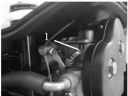
- ? Fordítsa a gázkar ütközőcsavarját az óramutató járásával megegyező vagy ellentétes irányba, amíg az előírt alapjárati fordulatszámot el nem éri. 1. Gázkar ütközőcsavarja
- ④ Az alapjárat beállítása után többször emelje a fordulatszámot a motor stabilitásának ellenőrzésére.
Célszerszámok és mérőeszközök
A karbantartáshoz és javításhoz különféle célszerszámokat és mérőeszközöket kell használni. A megfelelő szerszámok növelik a munkavégzés hatékonyságát, és megelőzik a személyi sérülést és a külmotor károsodását.
Célszerszámok
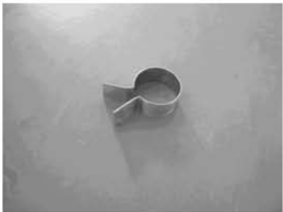
Dugattyú-bevezető
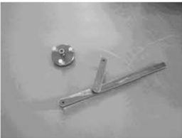
Lendkerékrögzítő és -lehúzó
- Hűtővíz ellenőrző nyílása
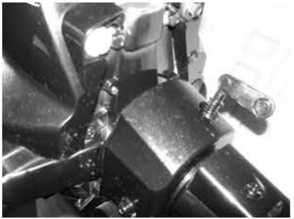
Csapágylehúzó
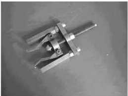
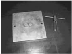
Szeleprugó-összenyomó
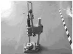
Olajtömítés-beütő szerszám
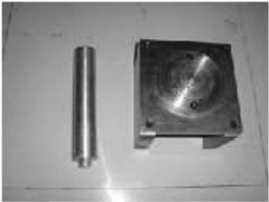
Házcsapágy-beütő
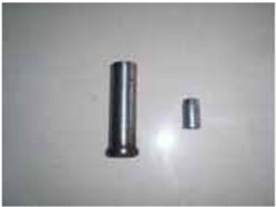
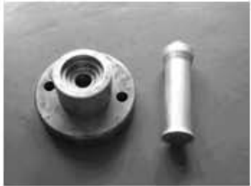
Alsó házfedél csapágybeütője
Ház olajtömítésének beütője
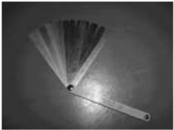
Védőlemezes siklócsapágy beütőszerszáma
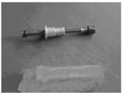
Hézagmérő
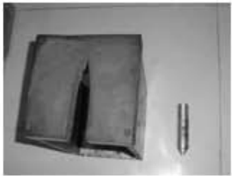
Alsó háztámasz és védőlemez nélküli siklócsapágy beütőszerszáma
Alsó háztámasz és hajtótengely-olajtömítés beütőszerszáma
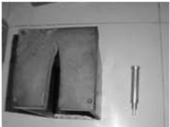
Mérőeszközök
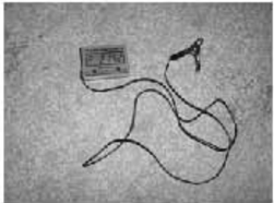
Digitális fordulatszámmérő
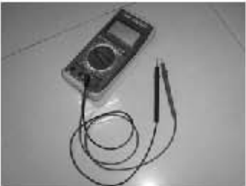
Digitális multiméter
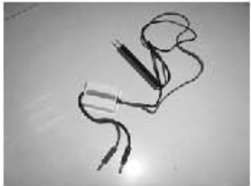
Csúcsfeszültség-adapter
Robbantott ábra és jelölések
Robbantott ábra
| Sorszám | Alkatrészszám | Leírás | Mennyiség | Megjegyzések |
|---|---|---|---|---|
| 1 | GB/TS743-2000 | Hatlapfejű csavar M6x40 | 4 | |
| 2 | F2.6-03000016 | Vízszivattyú rögzítőlemeze | 2 | |
| 3 | F4-03000021 | Vízszivattyú gumicsöve | 1 | |
| 4 | JASO F40419-953 | Vízszivattyú belső házának O-gyűrűje | 1 | |
| 5 | F2.6-03000015 | Vízszivattyú belső háza | 1 | |
| 6 | F2.6-03000100 | Járókerékegység | 1 | |
| 7 | F2.6-03000010 | Külső lemez | 1 | |
| 8 | F2.6-03000009 | O-gyűrű | 1 | |
| 9 | F4-03000013 | Pozicionálócsap Φ4x18 | 2 | |
| 10 | F2.6-03000007 | Vízszivattyú alapjának tömítése | 1 | |
| 11 | F2.6-03000008 | Vízszivattyú alapja | 1 |
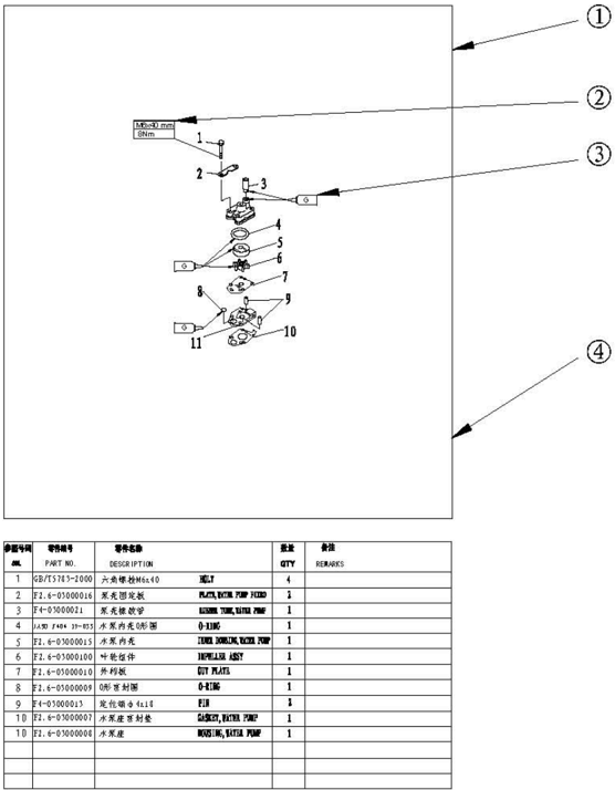
- 1 Alkatrészek robbantott ábrája
- Csavar műszaki adatai és előírt meghúzási nyomatéka
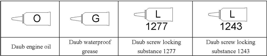
- Olaj, folyékony tömítőanyag vagy menetrögzítő felviteli helye
- Alkatrészek adatai
Jelölés
Műszaki adatok
Külmotor műszaki adatai
| Tétel | Tétel | Leírás | Tétel | Tétel | Leírás |
|---|---|---|---|---|---|
| Méretek | Teljes hossz | 645mm | Motor | Gyújtógyertya | BPR7HS |
| Méretek | Teljes szélesség | 343mm | Motor | Kipufogórendszer | Víz alatt |
| Méretek | Teljes magasság | 1013mm | Motor | Kenési rendszer | Szóróolajozás |
| Tömeg | Tömeg | 18.0kg | Üzemanyag: | Üzemanyagtípus | Normál ólommentes benzin |
| Teljesítmény | Maximális teljesítmény | 1.9Kw(2.6hp)@5500r/min | Üzemanyag: | Üzemanyag-előírás | PON86、RON91 |
| Teljesítmény | Teljes gázas üzem | 5250~5750r/min | Üzemanyag: | Üzemanyagtartály térfogata | 1.2L |
| Teljesítmény | Maximális üzemanyag-fogyasztás | 1.1L/h@5500r/min | Üzemanyag: | Ajánlott motorolaj | APISE、SF、SE-SF、 SG-CD SAE 10W30、10W40 |
| Teljesítmény | Alapjárati fordulatszám (üresben) | 1900±100r/min | Üzemanyag: | Motorolaj mennyisége | 0.35L |
| Motorblokk | Típus | 4 ütemű, OHV | Üzemanyag: | Ajánlott hajtóműolaj | Hipoid hajtóműolaj SAE #90 |
| Motorblokk | Hengerek száma | 1 | Üzemanyag: | Hajtóműolaj mennyisége | 75mm3 |
| Motorblokk | Lökettérfogat | 72cm3 | Tartókonzol | Billentési szög | 0°4°,8°,12° |
| Motorblokk | Furat × löket | 54.0mmX31.5mm | Tartókonzol | Felbillentési szög | 80° |
| Motorblokk | Sűrítési viszony | 9.0 | Tartókonzol | Kormányzási szög | 360° |
| Motorblokk | Karburátorok száma | 1 | Tartókonzol | Sebességváltó állásai | F-N |
| Motorblokk | Vezérlőrendszer | Kormánykaros vezérlés | Hajtóműegység | Áttételi viszony | 2.08(27/13) |
| Motorblokk | Indítórendszer | Berántóindító | Hajtóműegység | Fogaskerék típusa | Kúpfogaskerék |
| Motorblokk | Gyújtásvezérlő rendszer | T.C.I | Hajtóműegység | Hajócsavar forgásiránya | Óramutató járásával megegyező |
| Motorblokk | Indítási dúsítás | Szívatószelep | Hajtóműegység | Hajócsavar-hajtás | Bordázat |
Karbantartási adatok
Motorblokk
| Tétel | Tétel | Leírás | Tétel | Tétel | Tétel | Leírás |
|---|---|---|---|---|---|---|
| 0.1mm | Szelep | Szelephézag (hidegen) | Szívó | 0.08~0.12mm | ||
| Vetemedési határérték | 0.1mm | Szelep | Szelephézag (hidegen) | Kipufogó | 0.08~0.12mm | |
| Furat | 54.00~54.015mm | Felfekvő felület szélessége | Szívó | 1.84~2.26mm | ||
| Kopási határérték | 54.1mm | Felfekvő felület szélessége | Kipufogó | 1.84~2.26mm | ||
| Kúpossági határérték | 0.08mm | Ülékszélesség | Szívó | 0.6~0.8mm | ||
| Ovalitási határérték | 0.05mm | Ülékszélesség | Kipufogó | 0.6~0.8mm | ||
| Dugattyú átmérője | 58.950~58.965mm | Peremvastagság | Szívó | 0.7mm | ||
| Mérési pont magassága | Omm (a dugattyú aljától) | Peremvastagság | Kipufogó | 1.0mm | ||
| Dugattyú és henger közötti hézag | 0.035~0.065mm | Tányérátmérő | Szívó | 23.9~24.1mm | ||
| Csapszegfurat belső átmérője | 12.009~12.017mm | Tányérátmérő | Kipufogó | 21.9~22.1mm | ||
| Dugattyúcsapszeg külső átmérője | Dugattyúcsapszeg külső átmérője | 11.995~12.000mm | Szár külső átmérője | Szívó | 5.475~5.490mm | |
| 0.97~0.99mm | Szár külső átmérője | Kipufogó | 5.460~5.475mm | |||
| Vastagság, szélesség | 1.95~2.15mm | Vezető belső átmérője, szár és | Szívó | 5.500~5.512mm | ||
| Véghézag | 0.15~0.30mm | Vezető belső átmérője, szár és | Kipufogó | |||
| Kopási határérték | 0.40mm | vezető közötti hézag | Szívó | 0.010~0.037mm | ||
| Oldalhézag | Oldalhézag | vezető közötti hézag | Kipufogó | 0.025~0.052mm | ||
| 0.04~0.08mm | Szár ütési határértéke | Szár ütési határértéke | 0.03mm | |||
| Vastagság | 1.17~1.19mm | Tolórúd ütési határértéke | Tolórúd ütési határértéke | Tolórúd ütési határértéke | 0.5mm | |
| Szélesség | 2.30~2.50mm | Szeleprugó | Szabad hossz | Szabad hossz | 35.0mm | |
| Véghézag | 0.30~0.45mm | Szeleprugó | Szabad hossz határértéke | Szabad hossz határértéke | 34.0mm | |
| Kopási határérték | 0.60mm | Szeleprugó | Ferdeségi határérték | Ferdeségi határérték | 1.2mm | |
| Oldalhézag | 0.02~0.06mm | Hajtórúd | Kis fej belső átmérője | Kis fej belső átmérője | 12.006~12.02mm | |
| Vastagság | 1.87~1.95mm | Főtengely | Nagy fej olajhézaga | Nagy fej olajhézaga | 0.016~0.046mm | |
| Szélesség | 2.10~2.40mm | Forgattyúcsap szélessége | Forgattyúcsap szélessége | 21.0~21.1mm | ||
| Véghézag | 0.20~0.70mm | Forgattyúcsap átmérője | Forgattyúcsap átmérője | 23.969~23.984m m | ||
| Kopási határérték | 0.90mm | Főtengelycsap átmérője | Főtengelycsap átmérője | 21.980~21.993m m | ||
| Oldalhézag | 0.06~0.16mm | Ovalitási határérték | Ovalitási határérték | 0.01mm | ||
| Vezérműtengely | Szívó-/kipufogóbütyök magassága | 26.139~26.239mm | Termosztát | Szelep nyitási hőmérséklete | 58~62℃ | |
| Vezérműtengely | Szívó-/kipufogóbütyök magassága | 26.139~26.239mm | Termosztát | Teljes nyitás hőmérséklete | 70℃ | |
| Vezérműtengely | Alapkör átmérője | 21.950~22.050mm | Termosztát | Szelepemelkedés | 3mm | |
| Vezérműtengely | Csapátmérő | 14.966~14.984mm | Termosztát | Szelepemelkedés | 3mm | |
| Vezérműtengely | Vezérműtengely ütési határértéke | 0.03mm | Termosztát | Szelepemelkedés | 3mm |
Gyújtásrendszer
| Tétel | Leírás | Tétel | Tétel | Leírás |
|---|---|---|---|---|
| Gyújtási időzítés | BTDC30° | Gyertyahézag | Gyertyahézag | 0.6~0.7mm |
| T.C.I rendszer kimeneti csúcsfeszültsége | 130V | Gyújtóegység ellenállása | Primer tekercs | 1.6~1.9Ω |
| T.C.I légrés | 0.4~0.6mm | Gyújtóegység ellenállása | Szekunder tekercs | 5.8~7.0K Ω |
Meghúzási nyomaték
| Meghúzandó alkatrész | Meghúzandó alkatrész | Meghúzandó alkatrész | Alkatrész neve | Menetméret | Mennyiség | Nyomaték |
|---|---|---|---|---|---|---|
| Olajleeresztő | Olajleeresztő | Csavar | M8 | 1 | 18Nm | |
| Gyújtógyertya | Gyújtógyertya | M14 | 1 | 25 Nm | ||
| Berántóindító | Berántóindító | Csavar | M6 | 3 | 8 Nm | |
| Lendkerék-forgórész egysége | Lendkerék-forgórész egysége | Anya | M10 | 1 | 44 Nm | |
| Karburátor | Karburátor | Csavar | M6 | 2 | 8Nm | |
| Kipufogóvizsgáló | Kipufogóvizsgáló | Csavar | M8 | 1 | 20 Nm | |
| Hengerfej | 1. meghúzás | Csavar | M8 | 4 | 14 Nm | |
| 2. meghúzás | Csavar | M8 | 4 | 30 Nm | ||
| Henger | 1. meghúzás | Csavar | M6 | 6 | 5 Nm | |
| hengerfejfedél | 2. meghúzás | Csavar | M6 | 6 | 12 Nm | |
| Himbacsavar | Himbacsavar | Csavar | M6 | 2 | 10 Nm | |
| Ellenanya (himba) | Ellenanya (himba) | Anya | M6x0.75 | 2 | 10 Nm | |
| Olajtömítésház | Olajtömítésház | Csavar | M8 | 1 | 18Nm | |
| Motorblokk rögzítése | Motorblokk rögzítése | Csavar | M6 | 6 | 11Nm | |
| Termosztátfedél | Termosztátfedél | Csavar | M6 | 3 | 8 Nm | |
| Forgattyúház | 1. meghúzás | Csavar | M6 | 8 | 5 Nm | |
| 2. meghúzás | Csavar | M6 | 8 | 11 Nm | ||
| Hajtórúd | 1. meghúzás | Csavar | M7 | 2 | 5Nm | |
| 2. meghúzás | Csavar | M7 | 2 | 9 Nm | ||
| Olajszóró fogaskerékegység | Olajszóró fogaskerékegység | Csavar | M6 | 1 | 13 Nm | |
| Alsó egység | 1. meghúzás | Csavar | M6 | 3 | 3 Nm | |
| rögzítése | 2. meghúzás | Csavar | M6 | 3 | 8Nm | |
| Alsó egység házfedele | 1. meghúzás | Csavar | M6 | 2 | 6Nm | |
| Alsó egység házfedele | 2. meghúzás | Csavar | M6 | 2 | 11 Nm | |
| Anód | 1. meghúzás | Csavar | M6 | 1 | 3Nm | |
| Anód | 2. meghúzás | Csavar | M6 | 1 | 8Nm | |
| Vízszivattyúház | 1. meghúzás | Csavar | M6 | 4 | 3Nm | |
| Vízszivattyúház | 2. meghúzás | Csavar | M6 | 4 | 8Nm | |
| Vízszivattyú alapja | 1. meghúzás | Csavar | M6 | 1 | 3 Nm | |
| Vízszivattyú alapja | 2. meghúzás | Csavar | M6 | 1 | 8Nm | |
| Kormánykar rögzítése | Kormánykar rögzítése | Csavar | M8 | 1 | 26 Nm | |
| Váltókar konzolja | Váltókar konzolja | Csavar | M6 | 1 | 5Nm | |
| Forgókonzol | Forgókonzol | Anya | M6 | 4 | 12 Nm | |
| Szorítókonzol | Szorítókonzol | Anya | M8 | 1 | 16 Nm |
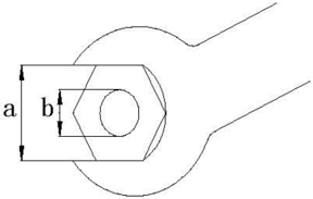
Általános meghúzási nyomaték
| Anya (a) | Csavar (b) | Nyomaték |
|---|---|---|
| 8mm | M5 | 5Nm |
| 10mm | M6 | 8 Nm |
| 12mm | M8 | 18 Nm |
| 14mm | M10 | 36 Nm |
| 17mm | M12 | 43 Nm |
Időszakos szerviz
Karbantartási ütemterv
| Tételek | Műveletek | Első karbantartás | Első karbantartás | Általános karbantartási időköz | Általános karbantartási időköz |
|---|---|---|---|---|---|
| Tételek | Műveletek | 10 óra (1 hónap) | 50 óra (3 hónap) | 100 óra (6 hónap) | 200 óra (1 év) |
| Anód | Ellenőrzés/csere | 0 | |||
| Gyújtógyertya | Tisztítás/beállítás/csere | O | |||
| Kenési pontok | Zsírzás | O | |||
| Csavarok és anyák | Ellenőrzés | O | O | ||
| Üzemanyagtartály és üzemanyagvezeték | Ellenőrzés | ||||
| Üzemanyagszűrő | Ellenőrzés/csere | O | |||
| Karburátor | Ellenőrzés/csere | O | |||
| Külmotor külseje | Ellenőrzés/csere | O | |||
| Alapjárati fordulatszám | Ellenőrzés/beállítás | O | |||
| Motorolaj | Csere | O | |||
| Szelephézag | Ellenőrzés/beállítás | O | |||
| Gyújtási időzítés | Ellenőrzés | O | |||
| T.C.I légrés | Ellenőrzés/beállítás | O | |||
| Termosztát | Ellenőrzés | O | |||
| Hűtővízjárat | Ellenőrzés/tisztítás | O | |||
| Hajtóműolaj | Csere | 0 | |||
| Hajócsavar | Ellenőrzés/csere |
VIGYÁZAT:
Sós, szenny- vagy iszapos vízben való üzemeltetés után azonnal öblítse át a külmotort édesvízzel.
Ólmozott benzin gyakori használatakor 100 óránként ellenőrizze a szelepet és az alkatrészeket.
Üzemanyagrendszer
- ÜZEMANYAGTARTÁLY, KARBURÁTOR, ÜZEMANYAG-SZIVATTYÚ ÉS ÜZEMANYAGCSŐ ELLENŐRZÉSE
Ellenőrizze, sérült-e vagy szivárog-e az üzemanyagtartály, a karburátor, az üzemanyag-szivattyú és az üzemanyagcső. Szükség esetén cserélje ki. Ellenőrizze, szennyezett-e a tartály üzemanyagszűrője. Szükség esetén tisztítsa meg vagy cserélje ki.
2. Üzemanyagcsap ellenőrzése
Ellenőrizze az üzemanyagcsap repedését, sérülését és szivárgását. Szükség esetén cserélje ki.
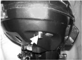
Motorblokk
Motorolajszint
- Az olajszint-ellenőrző nyílásnál ellenőrizze, hogy a motorolaj szintje az alábbi felső és alsó jelölés között van-e.
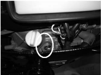
- Olajszintcsavar 2. Nívópálca
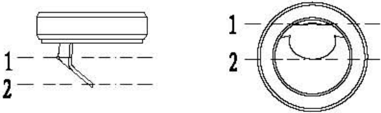
- 3.Felső szintjelölés 4. Alsó szintjelölés
- A felső jelölés felett eresszen le motorolajat; az alsó jelölés alatt töltsön utána a felső jelölésig.
VIGYÁZAT:
Járassa a motort néhány percig, majd állítsa le. Várjon néhány percet, és az olajszint-ellenőrző nyílásnál ellenőrizze újra a motorolaj szintjét.
Ha az olajszint továbbra sem megfelelő, szükség szerint töltsön utána vagy eresszen le olajat.
Motorolaj cseréje
- Távolítsa el az olajszintcsavart, valamint a leeresztőcsavart az alátéttel és tömítéssel együtt; eressze le a motorolajat.
- Szereljen be új tömítést és alátétet; szerelje be a leeresztőcsavart.
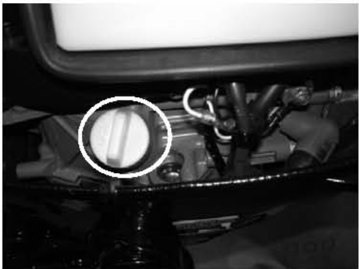
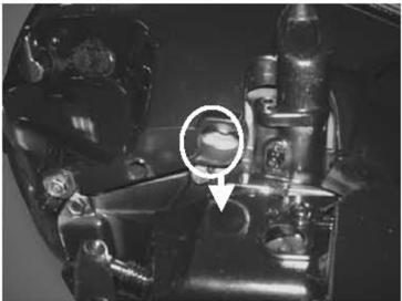
- Töltsön motorolajat a forgattyúházba az olajbetöltő nyíláson keresztül.
Motorolaj mennyisége: 0.35L
Olajtípus: API SE, SF, SE-SF, SG-CD SAE 10W30, 10W40
- Szerelje be az olajszintcsavart.
- 5.Ellenőrizze a motorolajszintet.
VIGYÁZAT:
A szelephézag beállítása előtt fordítsa a lendkereket az óramutató járásával megegyező irányba úgy, hogy a himba szabad helyzetben legyen (a sűrítési ütem holtpontján).
- Távolítsa el a biztonsági zsinórt a motorleállító kapcsolóból. Vegye le a gyertyapipát a gyújtógyertyáról.
- 2.Távolítsa el a hengerfejfedelet.
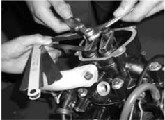
- Hézagmérővel mérje meg a himba és a szelepszár vége közötti hézagot; ha nem felel meg az előírásnak, állítsa be.
Szelephézag (hidegen): 0.08~0.12mm
- Távolítsa el a gyertyapipát és a gyújtógyertyát.
Gyújtógyertya
- 2.Tisztítsa le a szénlerakódást az elektródákról.
- Ellenőrizze az elektródák korrózióját és lerakódásait, valamint az alátét sérülését. Szükség esetén cserélje ki a gyújtógyertyát.
- Ellenőrizze, hogy a gyertyahézag megfelel-e az előírásnak. Szükség esetén cserélje ki a gyújtógyertyát.
- Szerelje be a gyújtógyertyát. Gyertyakulccsal húzza meg az előírt nyomatékkal.
Gyújtógyertya típusa: BPR7HS
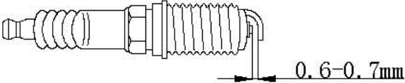
Előírt nyomaték: 25 Nm
Szelephézag
Vezérlőrendszer
Gázmarkolat
- Fordítsa a gázmarkolatot teljesen zárt helyzetbe.
- Ellenőrizze a gázbowden holtjátékát és azt, hogy a gázkar érinti-e a gázkar ütközőcsavarját.
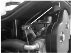
- Lazítsa meg a gázbowden rögzítőcsavarját, állítsa be a gázbowden helyzetét, majd húzza meg a rögzítőcsavart.
1.Gázbowden rögzítőcsavarja
Alapjárati fordulatszám
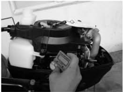
Ellenőrizze az alapjárati fordulatszámot, és szükség esetén állítsa be.
- 1.Melegítse elő a motort 5 percig.
- Csatlakoztassa a fordulatszámmérőt a gyújtógyertya vezetékéhez az alapjárati fordulatszám (RPM) méréséhez. Ha nem felel meg az előírásnak, állítsa be.
- Fordítsa a gázkar ütközőcsavarját az óramutató járásával megegyező vagy ellentétes irányba az előírt alapjárati fordulatszám eléréséig.
Alapjárati fordulatszám: 1800~2000 r/min
MEGJEGYZÉS:
Az óramutató járásával megegyező irányba fordítva nő az alapjárati fordulatszám.
Az óramutató járásával ellentétes irányba fordítva csökken az alapjárati fordulatszám.
VIGYÁZAT:
Az alapjárat beállítása előtt megfelelően állítsa be a gázbowden holtjátékát. Az alapjárat beállítása után szükség esetén újra beállíthatja a gázbowdent.
Hajtóműolajszint ellenőrzése
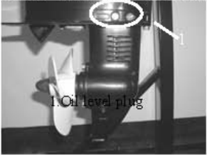
Távolítsa el az olajszintcsavart. Ha a hajtóműolaj kifolyik az olajszint-ellenőrző nyíláson, a betöltött mennyiség megfelelő; ellenkező esetben töltsön utána hajtóműolajat.
- Olajszintcsavar
Hajtóműolaj cseréje
- 1.Tartsa a külmotort függőleges helyzetben.
- 2.Helyezzen edényt a leeresztőcsavar alá.
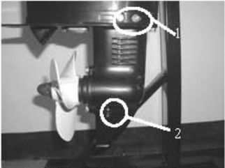
- 3.Távolítsa el a leeresztőcsavart és az olajszintcsavart, majd eressze le a hajtóműolajat.
- 4.Nyomásos töltőeszközzel töltsön hajtóműolajat a leeresztőcsavar nyílásán keresztül.
- Amikor a hajtóműolaj kifolyik az olajszint-ellenőrző nyíláson, szerelje be az olajszintcsavart. 5.
- 6.Szerelje be a leeresztőcsavart, majd törölje le a kifolyt hajtóműolajat.
1.Olajszintcsavar 2. Leeresztőcsavar
MEGJEGYZÉS:
Vizsgálja meg a leeresztett hajtóműolajat.
Ha a hajtóműolaj tejszerű, ellenőrizze az olajtömítést. Szükség esetén cserélje ki az olajtömítést.
VIGYÁZAT:
A leeresztőcsavar alátétét minden alkalommal ki kell cserélni.
Alsó egység szivárgásvizsgálata
Alsó egység háza
Hajtóműolaj
Csatlakoztassa a szivárgásvizsgálót az olajszint-ellenőrző nyíláshoz az alsó egység szivárgásának ellenőrzésére. Ha a
Általános ellenőrzés
Anód
Vizsgálja meg az alsó egység anódját és a motor anódját (a termosztát fedelén). Tisztítsa le a zsíros szennyeződést és vízkövet. Ha a kopás vagy sérülés meghaladja az 1/2 részt, cserélje ki az anódot.
VIGYÁZAT:
Az anódot ne zsírozza vagy fesse le, mert akkor nem működik megfelelően.
Kenési pontok
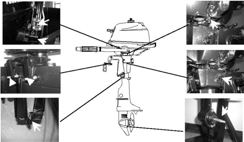
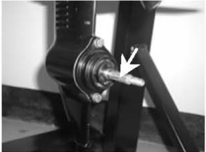
- Az ábra alapján vigyen fel vízálló zsírt a kenési pontokra.
- 2.Kenje be a hajócsavartengelyt korrózióálló zsírral.
Hűtővízjárat
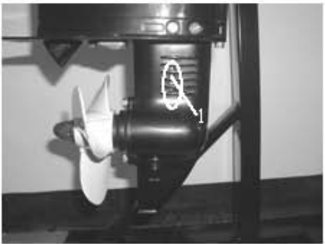
- 1.Vizsgálja meg a hűtővízjáratot. Eltömődés esetén tisztítsa meg.
Hűtővízjárat beömlőnyílása
- 2.Helyezze a külmotort vízbe, és győződjön meg arról, hogy a vízszint az antikavitációs lemez felett van, majd indítsa be a motort.
- 3.Ellenőrizze, folyik-e víz a hűtővíz ellenőrző nyílásából. Ha nincs vízáramlás vagy szakaszos, ellenőrizze a hűtővízjáratot.
1.Hűtővíz-beömlőnyílás
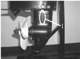
- Hűtővíz ellenőrző nyílása
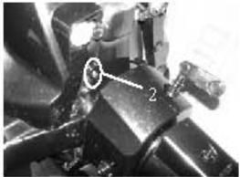
Berántóindító
FIGYELEM:
Szervizeléskor viseljen védőszemüveget és kesztyűt. A véletlen motorindítás elkerülésére távolítsa el a gyertyapipát és a biztonsági zsinórt a leállítókapcsolóból.
Robbantott ábra
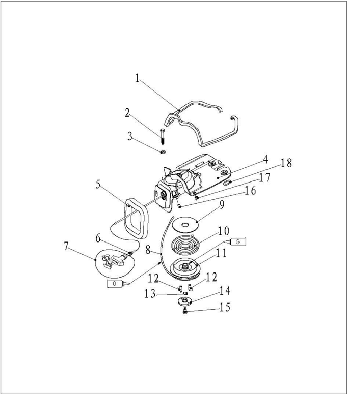
| Sorszám | Alkatrészszám | Leírás | Mennyiség | Megjegyzések |
|---|---|---|---|---|
| 1 | F2.6-04070002 | Habgumi tömítés | 1 | |
| 2 | CB/T5782-2000 | Csavar M6x60 | 3 | |
| 3 | CB/T97.1-85 | Alátét 6 | 3 | |
| 4 | F2.6-04070100 | INDÍTÓHÁZ | 1 | |
| 5 | F2.6-04070001 | Habgumi tömítés | 1 | |
| 6 | F2.6-04070008 | FOGANTYÚ CSILLAPÍTÓELEME | 1 | |
| 7 | F4-04130100 | INDÍTÓFOGANTYÚ-EGYSÉG | 1 | |
| 8 | F2.6-04070007 | INDÍTÓKÖTÉL Φ3 | 1 | |
| 9 | F2.6-04070003 | NYOMÓALÁTÉT | 1 | |
| 10 | F4-04130005 | SPIRÁLRUGÓ | 1 |
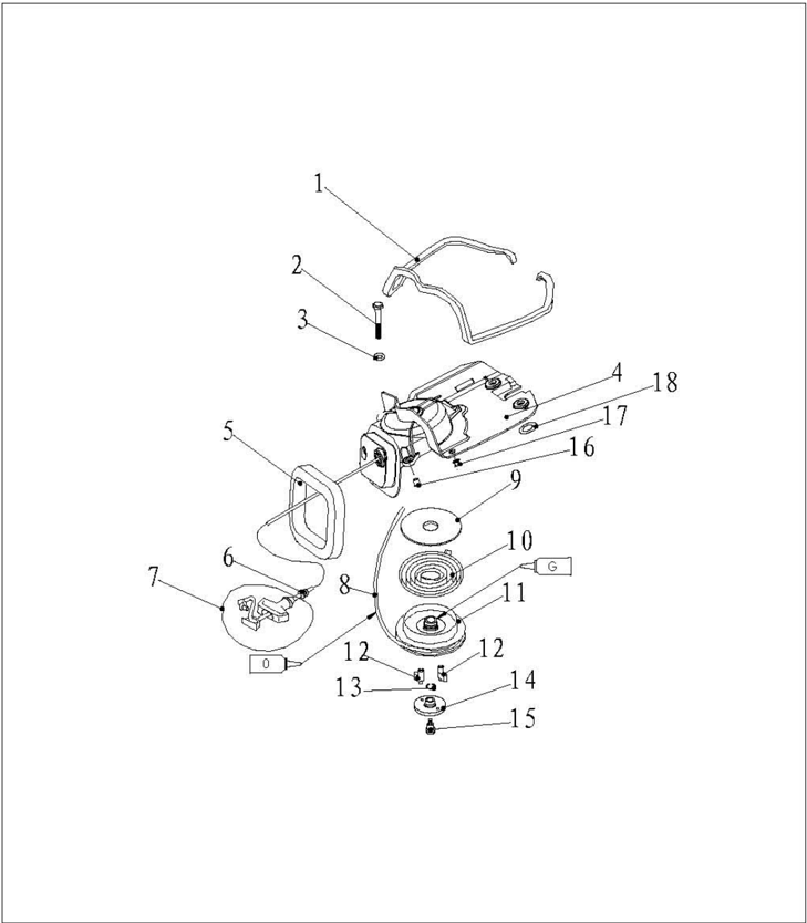
| Sorszám | Alkatrészszám | Leírás | Mennyiség | Megjegyzések |
|---|---|---|---|---|
| 11 | F2.6-04070004 | Indító kötéldobja | 1 | |
| 12 | F2.6-04070005 | HAJTÓKÖRÖM | 2 | |
| 13 | F4-04130007 | Indítólemez rugós kapcsa | 1 | |
| 14 | F2.6-04070006 | NYOMÓLEMEZ | 1 | |
| 15 | F4-04130008 | INDÍTÓCSAVAR | 1 | |
| 16 | F2.6-04000024 | INDÍTÓPERSELY | 3 | |
| 17 | F2.6-04000034 | ÜZEMANYAGTARTÁLY CSILLAPÍTÓELEME B | 2 | |
| 18 | F2.6-04000025 | INDÍTÓPERSELY | 2 |
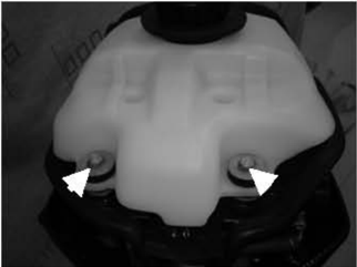
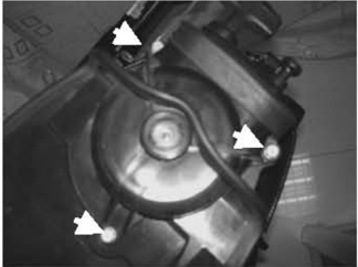
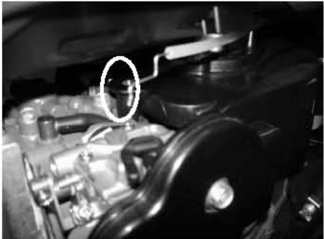
- Nyissa fel a felső motorburkolatot.
- 2.Távolítsa el az üzemanyagtartály rögzítőcsavarjait.
- 3.Távolítsa el az üzemanyagtartályt, és vegyen ki három csavart.
- 4.Emelje fel az indítót, és válassza le a szívatóbowdent a karburátorról.
- 5.Távolítsa el az indítót.
Szétszerelés
Indítókötél cseréje
- Húzza ki az indítókötelet, és illessze a kötéldob hornyába. Fordítsa a kötéldobot az óramutató járásával megegyező irányba, amíg a spirálrugó tehermentessé válik.
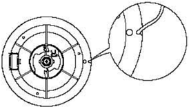
- Húzza ki teljesen az indítókötelet.
- Vegye le az indítófogantyú fedelét a fogantyúról, és távolítsa el az indítókötelet. Oldja ki a kötél végén lévő csomót.
- Húzza ki teljesen az indítókötelet.
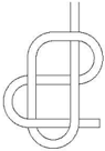
- Vezesse az új indítókötelet az indítóegységbe, és rögzítse a kötéldobhoz és az indítófogantyúhoz. A kötél végére kössön csomót az ábra szerint.
- Illessze az indítókötelet a kötéldob hornyába, és fordítsa a kötéldobot több fordulattal az óramutató járásával ellentétes irányba.
- Húzza meg többször az indítófogantyút, és ellenőrizze a kötéldob egyenletes forgását. Szükség esetén ismételje meg a 6. és 7. lépést.
Szétszerelés és ellenőrzés
- Távolítsa el az indítókötelet.
- Távolítsa el az indítócsavart, majd a nyomólemezt és a hajtókörmöt.
- 3.Távolítsa el a kötéldobot.
- FIGYELMEZTETÉS: Óvatosan szerelje le a kötéldobot, nehogy a spirálrugó kiugorjon és személyi
sérülést okozzon.
- Távolítsa el a spirálrugót.
- Ellenőrizze a hajtóköröm repedését, kopását és sérülését. Szükség esetén cserélje ki.
- Vizsgálja meg a hajtórugó törését, elhajlását és sérülését. Szükség esetén cserélje ki.
- Ellenőrizze a spirálrugó törését, elhajlását és sérülését. Szükség esetén cserélje ki.

Végezze el a szétszerelési lépéseket fordított sorrendben.
- 1.Helyezze az indítót a motorblokkra.
- 2.Csavarja be a hatlapfejű csavart, és húzza meg az előírt nyomatékkal. Előírt nyomaték: 8Nm
Gyújtásrendszer
FIGYELEM:
A gyújtásrendszer ellenőrzése és javítása közben tartsa távol kezét, ruháját, haját és személyes tárgyait a forgó lendkeréktől.
A gyújtótekercset szigetelt munkapadon ellenőrizze az áramszivárgás és áramütés elkerülésére.
Működő motornál az áramütés elkerülésére ne érintse meg a gyújtótekercset vagy gyújtógyertyát. A vezetékeket tartsa távol a forgó lendkeréktől, nehogy elvágja őket vagy elkoptassa a szigetelésüket.
Rögzítőelemek, például anyák és csavarok cseréjekor kizárólag eredeti gyártói alkatrészek vagy azonos anyagú és szilárdságú alkatrészek használhatók. Az alkatrészeket az előírt nyomatékkal kell meghúzni.
Robbantott ábra
Összeszerelés
Beszerelés
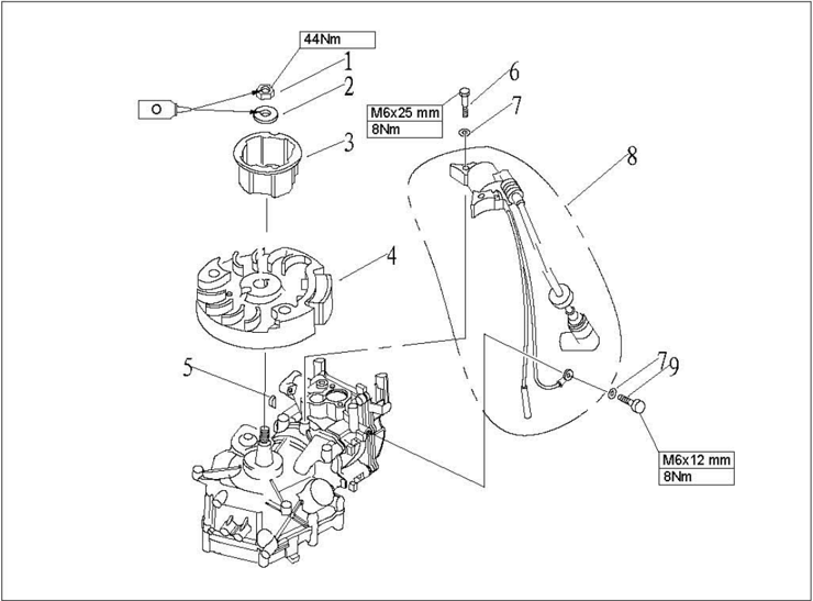
| Sorszám | Alkatrészszám | Leírás | Mennyiség | Megjegyzések |
|---|---|---|---|---|
| 1 | GB/T6171-86 | Anya M10x1.25 | 1 | |
| 2 | F4-04000021 | Lendkerék alátétje | 1 | |
| 3 | F2.6-04000016 | Indítópersely | 1 | |
| 4 | F2.6-04000400 | Lendkerékegység | 1 | |
| 5 | F4-04000019 | Lendkerék félholdretesze | 1 | |
| 6 | GB/T5783-2000 | Csavar M6x25 | 2 | |
| 7 | GB/T97.1-85 | Alátét 6 | 3 | |
| 8 | F2.6-04000600 | Gyújtótekercs-egység | 1 | |
| 9 | GB/T5783-2000 | Csavar M6x12 | 1 |
Kapcsolási rajz
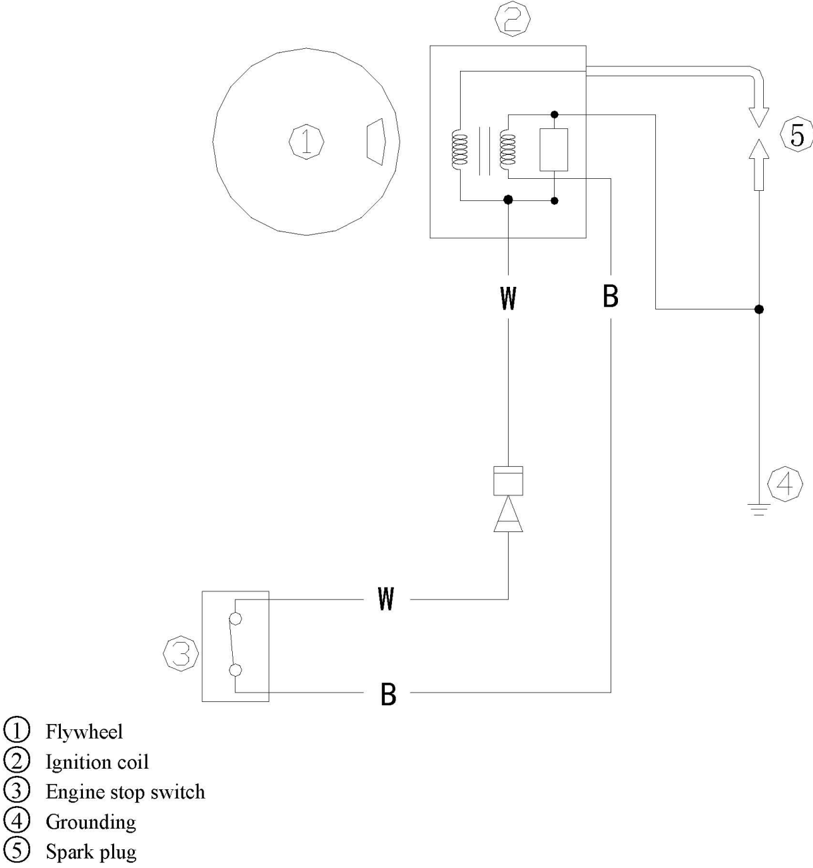
Vezetékköteg színei: W Fehér
B Fekete
Gyújtógyertya szikrája
- Vegye le a gyertyapipát a gyújtógyertyáról.
- 2.Csatlakoztassa a gyújtásvizsgálót a gyertyapipához.
- 3.S Indítsa be a motort, és figyelje a szikrákat a vizsgáló kisülési ablakán keresztül.
FIGYELMEZTETÉS:
Ne érintse meg a vizsgáló mérővezetékének csatlakozási pontjait.
Tartsa távol a gyúlékony gázokat és folyadékokat a szikra okozta gyulladás és baleset megelőzésére.
- Gyújtótekercs csúcsfeszültsége
- Távolítsa el a gyertyapipát.
- ② Válassza le a gyújtótekercs kivezetését (W).
- ③ Digitális multiméterrel és csúcsfeszültség-adapterrel mérje meg a gyújtótekercs kimeneti csúcsfeszültségét. Ha kisebb az előírtnál, ellenőrizze a gyújtótekercset.
Kimeneti csúcsfeszültség: 130V (1500 r/min)
Digitális multiméter
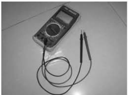
- Gyújtótekercs ellenállása
- (1 Távolítsa el a gyújtótekercset és a gyertyapipát.
- Mérje meg a gyújtótekercs ellenállását. Ha nem felel meg az előírásnak, cserélje ki.
- Ellenállás: 1.6~1.9 Q (mérő (+) pólusa: fehér vezeték; mérő (-) pólusa: fekete vezeték) 5.8~7.0k Q (mérő (+) pólusa: fehér vezeték; mérő (-) pólusa: nagyfeszültségű vezeték)
Csúcsfeszültség-adapter
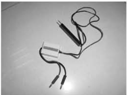
Gyertyapipa
- 1.Távolítsa el a gyújtógyertyát. Ellenőrizze a gyertyapipa törését. Szükség esetén cserélje ki.
- Szerelje fel a gyertyapipát. Fordítsa az óramutató járásával megegyező irányba, amíg meg nem szorul.
Lendkerék karbantartása
- 1.Lendkerékrögzítővel távolítsa el az anyát és az indítótárcsát; lendkeréklehúzóval távolítsa el a lendkereket.
- 2.Ellenőrizze a lendkerék sérülését és az állandómágnes-rész rögzítettségét. Szükség esetén cserélje ki.
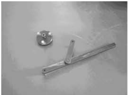
Gyújtótekercs ellenőrzése
Üzemanyagrendszer (részletesen)
FIGYELEM:
A benzin gyúlékony és erősen illékony folyadék. Szivárgása tüzet és robbanást okozhat. Ne indítsa be a motort, amíg az üzemanyagrendszer valamennyi csatlakozását nem kapcsolta össze vagy szerelte be. A karbantartás befejezése után rövid ideig helyezze nyomás alá az üzemanyagrendszert a szivárgás ellenőrzésére.
Robbantott ábra
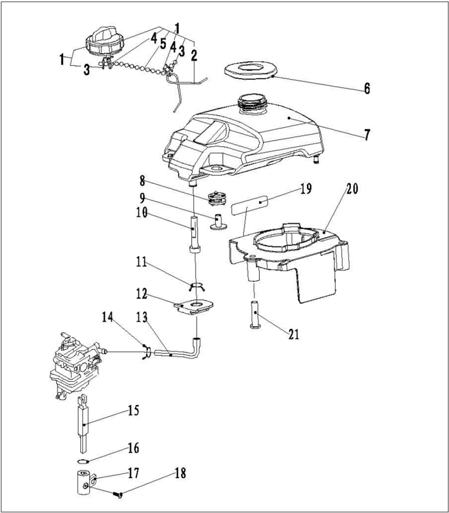
| Sorszám | Alkatrészszám | Leírás | Mennyiség | Megjegyzések |
|---|---|---|---|---|
| 1 | F4-04120100 | TANKSAPKAEGYSÉG | 1 | |
| 2 | F4-04120103 | Elvesztést megakadályozó torziós rugó | 1 | |
| 3 | F4-04120105 | Elvesztést megakadályozó rögzítőkapocs | 2 | |
| 4 | F4-04120106 | Acélhuzal rögzítőgyűrű | 2 | |
| 5 | F4-04120104 | Rögzítőlánc | 1 | |
| 6 | F2.6-04000033 | Üzemanyagtartály nyílásának csillapítóeleme | 1 | |
| 7 | F2.6-04000026 | Belső üzemanyagtartály | 1 | |
| 8 | F2.6-04000027 | Üzemanyagtartály csillapítóeleme A | 2 | |
| 9 | F2.6-04000028 | Üzemanyagtartály csillapítócsöve | 2 | |
| 10 | F4-04120005 | Üzemanyagtartály szűrője | 1 |
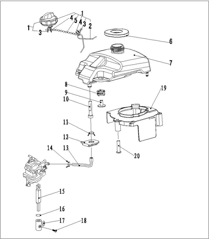
| Sorszám | Alkatrészszám | Leírás | Mennyiség | Megjegyzések |
|---|---|---|---|---|
| 11 | F4-05000010 | OLAJCSŐ RUGÓJA | 1 | |
| 12 | F4-04000032 | OLAJCSŐ CSILLAPÍTÓELEME | 1 | |
| 13 | F2.6-04000029 | Üzemanyagcső | 1 | |
| 14 | F2.6-04000030 | Üzemanyagcső rugója C | 1 | |
| 15 | F2.6-04000017 | Üzemanyag-elzáró szelep összekötőrúdja | 1 | |
| 16 | JASOF40424-014 | Üzemanyag-elzáró szelep O-gyűrűje Φ13.8x2.4 | 1 | |
| 17 | F2.6-00000004 | OLAJKAPCSOLÓ GOMBJA | 1 | |
| 18 | CB/T823-2000 | Félgömbfejű csavar M5x8 | 1 | |
| 19 | F2.6-04000022 | Lendkerék légterelője | 1 | |
| 20 | F2.6-04000023 | Légterelő távtartócsöve | 3 |
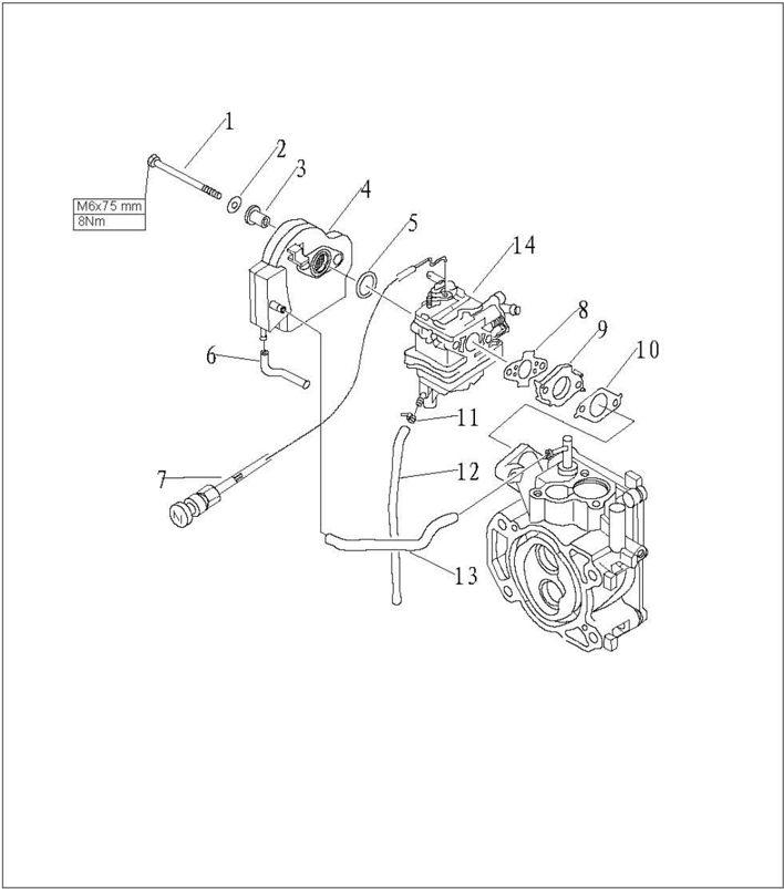
| Sorszám | Alkatrészszám | Leírás | Mennyiség | Megjegyzések |
|---|---|---|---|---|
| 1 | GB/T5782-2000 | Csavar M6x75 | 2 | |
| 2 | GB/T97.1-85 | Alátét 6 | 2 | |
| 3 | F2.6-04000012 | SZÍVÓHANGTOMPÍTÓ PERSELYE | 2 | |
| 4 | F2.6-04000300 | Szívóhangtompító-egység | 1 | |
| 5 | JAS0F40424-021 | Szívóhangtompító O-gyűrűje | 1 | |
| 6 | F2.6-04000015 | Szellőzőtömlő B Φ2.5xΦ7x72 | 1 | |
| 7 | F2.6-04070200 | Szívatókar-egység | 1 | |
| 8 | F2.6-04000018 | KARBURÁTOR LÉGTÖMÍTÉSE | 1 | |
| 9 | F2.6-04000011 | KARBURÁTOR SZIGETELŐELEME | 1 | |
| 10 | F2.6-04000010 | KARBURÁTOR LÉGTÖMÍTÉSE | 1 | |
| 11 | HT2.5x60 | BILINCS 60x2.5 | 1 | |
| 12 | F2.6-04000013 | Karburátor leeresztőtömlője Φ4xΦ7x140 | 1 | |
| 13 | F2.6-04000014 | Szellőzőtömlő A Φ5xΦ9x130 | 1 | |
| 14 | F2.6-04000200 | Karburátoregység | 1 |
Üzemanyagtartály eltávolítása és ellenőrzése

- Nyissa fel a felső motorburkolatot.
- 2.Távolítsa el az üzemanyagtartály két rögzítőcsavarját.
- Húzza ki az üzemanyagtartályt.
- Válassza le az üzemanyagcsövet az üzemanyagtartályról.
- Vizsgálja meg az üzemanyagtartály és a tanksapka repedését, szivárgását és sérülését. Szükség esetén cserélje ki.
- Vizsgálja meg a tartályszűrő szennyezettségét és eltömődését. Szükség esetén tisztítsa meg vagy cserélje ki.
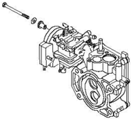
Szívórendszer eltávolítása és ellenőrzése
- 1.Távolítsa el a légszűrő rögzítőcsavarját.
- 2.Távolítsa el a légszűrőt és a karburátort.
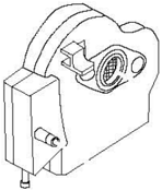
- 3.Ellenőrizze a légszűrő repedését és sérülését. Szükség esetén cserélje ki.
Motorblokk (részletesen)
FIGYELEM:
A karbantartás alatti véletlen motorindítás megelőzésére tegye meg a megfelelő biztonsági intézkedéseket, és vegye le a gyertyapipát a gyújtógyertyáról.
Robbantott ábra
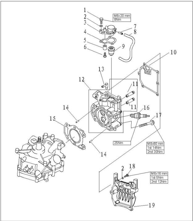
| Sorszám | Alkatrészszám | Leírás | Mennyiség | Megjegyzések |
|---|---|---|---|---|
| 1 | GB/T5783-2000 | Csavar M6X20 | 3 | |
| 2 | GB/T97.1-85 | LAPOS ALÁTÉT 6 | 9 | |
| 3 | F2.6-04000501 | TERMOSZTÁTFEDÉL | 1 | |
| 4 | F4-04000011 | TERMOSZTÁTTÖMÍTÉS | 1 | |
| 5 | P4-04070003 | Termosztátfedél anódja | 1 | |
| 6 | GB/T818-85 | Félgömbfejű csavar M5x25 | 1 | |
| 7 | F4-04010002 | Vízcső-csatlakozó | 1 | |
| 8 | F2.6-04000007 | VÍZCSŐ Φ5xΦ9x245 | 1 | |
| 9 | T15-04000010 | TERMOSZTÁT | 1 | |
| 10 | F2.6-04000005 | HENGERFEJFEDÉL TÖMÍTÉSE | 1 | |
| 11 | 166F-010104 | SZELEPVEZETŐ PERSELY | 2 | |
| 12 | F2.6-04040100 | HENGERFEJEGYSÉG | 1 | |
| 13 | F15-04000005 | Vízfúvóka-egység (7/6) | 1 | |
| 14 | P15-00000013 | Csap 4x12 | 2 |
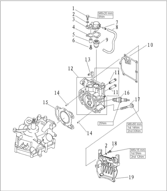
| Sorszám | Alkatrészszám | Leírás | Mennyiség | Megjegyzések |
|---|---|---|---|---|
| 15 | F2.6-04000001 | HENGERFEJTÖMÍTÉS | 1 | |
| 16 | BPR7HS | GYÚJTÓGYERTYA | 1 | |
| 17 | F4-04000034 | CSAVAR | 4 | |
| 18 | GB/T5783-2000 | Csavar M6x16 | 6 | |
| 19 | F2.6-04000006 | HENGERFEJFEDÉL | 1 |
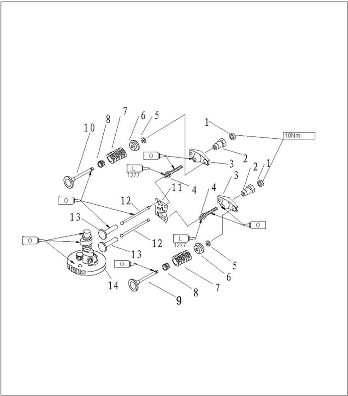
| Sorszám | Alkatrészszám | Leírás | Mennyiség | Megjegyzések |
|---|---|---|---|---|
| 1 | 166F-010011 | ELLENANYA | 2 | |
| 2 | 166F-010010 | HIMBACSAP | 2 | |
| 3 | 166F-010009 | SZELEPHIMBA | 2 | |
| 4 | 116F-010008 | HIMBACSAVAR | 2 | |
| 5 | 166F-010006 | SZELEPRÖGZÍTŐ | 2 | |
| 6 | F4-04080010 | SZELEPRUGÓ TÁNYÉRJA | 2 | |
| 7 | F4-04080008 | SZELEPSZÁR RUGÓJA | 2 | |
| 8 | 166F-010003 | SZELEPSZÁR-TÖMÍTÉS | 2 | |
| 9 | 166F-010001 | SZÍVÓSZELEP | 1 | |
| 10 | 166F-010002 | KIPUFOGÓSZELEP | 1 | |
| 11 | F2.6-04040001 | TOLÓRÚD LEMEZE | 1 | |
| 12 | F2.6-04000002 | SZELEP TOLÓRÚDJA | 2 | |
| 13 | 166F-000001 | SZELEPEMELŐ | 2 | |
| 14 | F2.6-04000100 | VEZÉRMŰTENGELY-EGYSÉG | 1 |
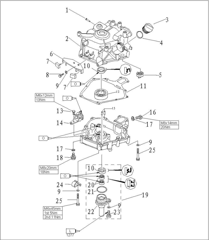
| Sorszám | Alkatrészszám | Leírás | Mennyiség | Megjegyzések |
|---|---|---|---|---|
| 1 | T15-04010202 | VÍZCSŐ | 1 | |
| 2 | F2.6-04010100 | FORGATTYÚHÁZ | 1 | |
| 3 | F15-07050004 | OLAJDUGÓ | 1 | |
| 4 | JAS0F40431-020 | O-GYŰRŰ JAS0F40431-020 | 1 | |
| 5 | F2.6-04010102 | SZINTMÉRŐ | 1 | |
| 6 | F2.6-04000008 | CSILLAPÍTÓ KONZOLJA | 1 | |
| 7 | F2.6-04000009 | GUMI CSILLAPÍTÓBLOKK | 2 | |
| 8 | GB/T5783-2000 | Csavar M6x20 | 2 | |
| 9 | GB/T97.1-85 | Alátét 6 | 11 | |
| 10 | F2.6-04010001 | Főtengely olajtömítése SD20x30x7HS | 2 | |
| 11 | F2.6-04000004 | FORGATTYÚHÁZ ÖSSZETETT TÖMÍTÉSE | 1 | |
| 12 | 62/22C3 | GOLYÓSCSAPÁGY | 1 | |
| 13 | GB/T5783-2000 | Csavar M6x12 | 1 | |
| 14 | F2.6-04050100 | FOGASKERÉKEGYSÉG | 1 |
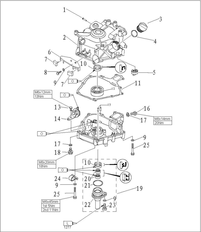
| Sorszám | Alkatrészszám | Leírás | Mennyiség | Megjegyzések |
|---|---|---|---|---|
| 15 | F15-00000013 | Csap 4x12 | ||
| 16 | GB/T5783-2000 | Csavar M8x14 | ||
| 17 | F4-04000006 | ALÁTÉT | ||
| 18 | F4-04000001 | OLAJLEERESZTŐ CSAVAR M8x20 | ||
| 19 | F2.6-04060000 | OLAJTÖMÍTÉSHÁZ-EGYSÉG | ||
| 20 | F2.6-04060002 | Felső hajtótengely-olajtömítés K-5657 | ||
| 21 | F4-04060002 | Olajtömítésház O-gyűrűje | ||
| 22 | F2.6-04060001 | OLAJTÖMÍTÉSHÁZ | ||
| 23 | GB/T5783-2000 | Csavar M8x20 | ||
| 24 | F25-05000013 | Bilincs A | ||
| 25 | GB/T5782-2000 | Csavar M6x45 |
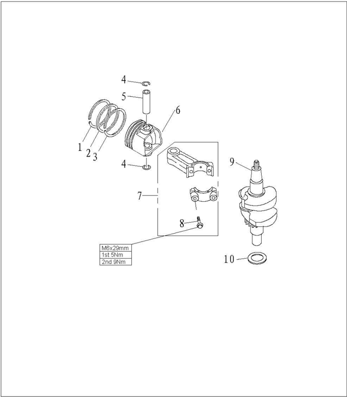
| Sorszám | Alkatrészszám | Leírás | Mennyiség | Megjegyzések |
|---|---|---|---|---|
| 1 | F2.6-04020002 | DUGATTYÚGYŰRŰ1 | 1 | |
| 2 | F2.6-04020003 | DUGATTYÚGYŰRŰ2 | 1 | |
| 3 | F2.6-04020004 | ÖSSZETETT OLAJLEHÚZÓ GYŰRŰ | 1 | |
| 4 | F2.6-04020006 | BIZTOSÍTÓGYŰRŰ | 2 | |
| 5 | F2.6-04020005 | DUGATTYÚCSAPSZEG | 1 | |
| 6 | F2.6-04020001 | DUGATTYÚ | 1 | |
| 7 | F2.6-04020100 | HAJTÓRÚD | 1 | |
| 8 | F2.6-04020103 | Csavar M6x30 | 2 | |
| 9 | F2.6-04030000 | FŐTENGELYEGYSÉG | 1 | |
| 10 | F2.6-04000003 | LAPOS ALÁTÉT | 1 |
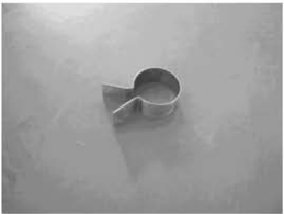
Dugattyú-bevezető
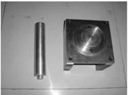
Házcsapágy-beütő
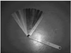
Hézagmérő
Motorblokk kiszerelése a külmotorból
- Nyissa fel a felső motorburkolatot.
- 2.Távolítsa el az üzemanyagtartályt és az indítót.
- Távolítsa el a lendkerékburkolatot és a gázbowdent.
- 4.Távolítsa el a légszűrőt és a karburátort.
- Távolítsa el a motorblokkot és a felső házat összekötő csavarokat.
- 6.Emelje ki a motorblokkot, és helyezze a munkapadra.
Szétszerelés és ellenőrzés
Hengerfej
Szétszerelés
- 1.Távolítsa el a hengerfejfedél csavarjait.
- 2.A hengerfej csavarjait a hengerfej számozásával ellentétes sorrendben távolítsa el.
- 3.Távolítsa el a forgattyúház fedelét. Távolítsa el a szelep tolórúdját.
Célszerszámok
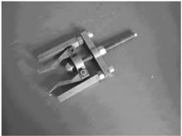
Csapágylehúzó
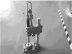
Olajtömítés-beütő szerszám
Szeleprugó-összenyomó
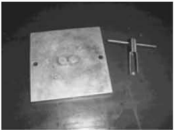
Ház olajtömítésének beütője
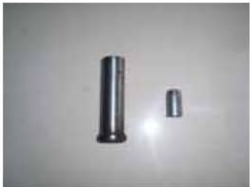
- 4.Távolítsa el a himbacsapot, a himbát, a himbatengelyt és a tolórúd lemezét.
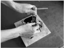
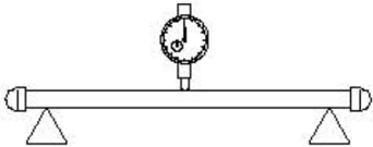
Tolórúd
Vizsgálja meg a szelep tolórúdjának ütését. Az előírt érték túllépésekor cserélje ki. A szelep tolórúdjának ütési határértéke: 0.5mm
Szelep és szelepvezető
- 1.Vizsgálja meg a szelepülék szélességét. Ha nem esik az előírt tartományba, javítsa meg a szelepüléket. Szelepülék szélessége: 0.6~0.8mm
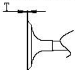
- Vizsgálja meg a szeleptányér peremének vastagságát (T). Ha nem felel meg az előírt értéknek, cserélje ki a szelepet. A szelep peremvastagsága: T
- 3.Vizsgálja meg a szelepszár átmérőjét. Ha nem esik az előírt tartományba, cserélje ki a szelepet. Szelepszár átmérője:
- 4.Mérje meg a szelepszár ütését. Ha meghaladja a határértéket, cserélje ki a szelepet. Szelepszár ütési határértéke: 0.03mm
- 5.Mérje meg a szelepvezető belső átmérőjét.
Szívószelep: 0.7mm
Kipufogószelep: 1.0omm
Szívószelep: 5.475~5.490mm
Kipufogószelep: 5.460~5.475mm
Szelepvezető belső átmérője: 5.500~5.512m
VIGYÁZAT:
Szelepcsere esetén használjon új szelepvezetőt és szelepszár-olajtömítést.
Szeleprugó
- 1.Mérje meg a szeleprugó szabad hosszát. Ha kisebb az előírt értéknél, cserélje ki.
- 2.Mérje meg a szeleprugó ferdeségét. Az előírt határérték túllépésekor cserélje ki.
Minimális szabad hossz: 34mm
Maximális ferdeségi határérték: 1.2mm
- Tisztítsa le a szénlerakódást a szelepről.
- Vigyen fel egyenletes, vékony réteg kék jelölőfestéket a szelepülék tömítőfelületére.
- Szelepcsiszoló szerszámmal csiszolja össze a szelepet és a szelepüléket.
- Mérje meg a szelepülék szélességét.
A szelep felülete kék jelölőfestékkel van bevonva.
Ha a szelep és a szelepülék nem illeszkedik, vagy a szelepülék szélessége nem felel meg az előírt értéknek, munkálja meg és csiszolja össze a szelepüléket.
Ha az érintkezési felület nem egyenletes, cserélje ki a szelepvezetőt.
Szelepülék szélessége: 0.6~0.8mm
Maximális szelepülék-szélesség: 1.1mm
Szelepülék marása
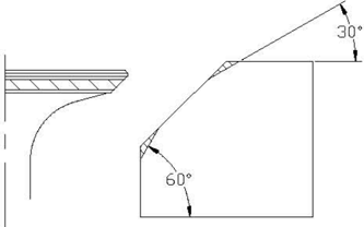
- 1.A szelepülék szélességét 45°-os szelepülékmaróval állítsa be. Fordítsa a marót az óramutató járásával megegyező irányba, amíg a szelepülék felülete sima nem lesz.
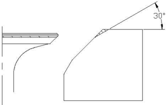
- 2.Ha a szelepülék a szelepfelület közepére esik, de túl széles, 30°-os maróval munkálja meg a felső szélét, 60°-os maróval pedig az alsó szélét a szélesség csökkentéséhez.
- Ha a szelepülék túl keskeny és a szelepfelület felső szélére esik, 30°-os maróval munkálja meg az ülék felső szélét, majd szükség esetén 45°-os maróval állítsa be az ülék szélességét.
Szelephimba
Ellenőrizze a himba repedését, kilyukadását és sérülését. Szükség esetén cserélje ki.
Szelepvezető cseréje
- 1.Üsse ki a szelepvezetőt az égéstér felől.
- 2.Üsse be az új szelepvezetőt a hengerfej teteje felől.
MEGJEGYZÉS:
Beszerelés előtt kenje be olajjal a vezető felületét.
- 3.Dörzsárral munkálja meg a vezető belső átmérőjét az előírt értékre.
Szelepvezető belső átmérője: 5.500~5.512mm
MEGJEGYZÉS:
A dörzsár kihúzásakor ne forgassa az óramutató járásával ellentétes irányba.
Szelepülék ellenőrzése
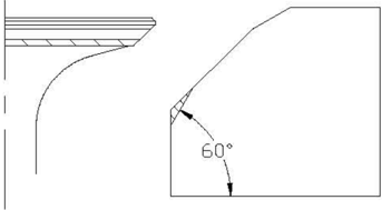
- 4.Ha a szelep tömítőfelülete túl keskeny és a szelepfelület alsó szélére esik, 60°-os maróval munkálja meg az ülék alsó szélét, majd szükség esetén 45°-os maróval állítsa be az ülék szélességét.
- Vigyen fel egyenletes, vékony réteg csiszolópasztát a szelepülékre, és szelepcsiszoló szerszámmal csiszolja össze a szelepet.
- Tisztítsa le a megmaradt csiszolópasztát.
- 7.Ellenőrizze újra a szelepülék szélességét.
VIGYÁZAT:
Ne csiszolja túl a szelepet. A csiszolószerszámot egyenletesen forgassa 40~50N lefelé irányuló erővel. Ne kerüljön csiszolópaszta a tolórúdra vagy a szelepvezetőre.
Termosztát
- Távolítsa el a termosztátfedelet és a termosztátot.
- 2.S Függessze a termosztátot egy vízzel teli edénybe.
- 3.Melegítse az edényt.
- 4.Vizsgálja meg a szelep emelkedését az előírt vízhőmérsékleten. Ha nem felel meg az előírásnak, cserélje ki.
- 5.Szerelje be a termosztátot és fedelét. Húzza meg a csavarokat az előírt nyomatékkal.
| Vízhőmérséklet | Emelkedés magassága |
|---|---|
| 58~62℃ | 0.05mm szelepemelkedés |
| 70℃ felett | 3mm felett |
Forgattyúház
Szétszerelés
- A forgattyúházfedél számozásával ellentétes sorrendben távolítsa el a csavarokat.
- 2.Távolítsa el a forgattyúház fedelét.
- 3.Távolítsa el a vezérműtengelyt és a szelepemelőt.
- Távolítsa el a hajtórúd csavarját és fedelét, majd a hajtórúd- és dugattyúegységet.
- Fogóval távolítsa el a biztosítógyűrűt, majd a dugattyúcsapszeget és a dugattyút.
- 6.Távolítsa el a forgattyúházat és tömítését.
- 7.Távolítsa el az olajszóró fogaskerékegységet.
- 8.Távolítsa el az olajtömítésház csavarjait, majd az olajtömítésházat és az olajtömítést.
Dugattyú
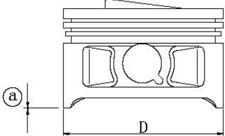
Mérje meg a dugattyú külső átmérőjét az előírt mérési ponton. Ha nem felel meg az előírásnak, cserélje ki.
Dugattyú átmérője:
53.950~53.965mm
Mérési pont @: Omm
Hengerfurat
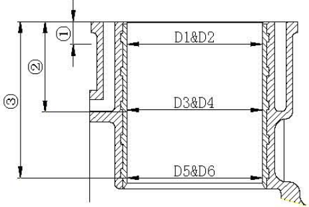
- Mérje meg a hengerfuratot külön-külön a ①, , ③ mérési pontokon. Minden pontnál mérjen a forgattyúházzal párhuzamos D1, D3, D5 helyeken, valamint a főtengelyre merőleges D2, D4, D6 helyeken.
Mérési pont magassága:
- ②40mm;
①100mm;
③70mm
Hengerfurat:
54.00~54.015mm
Határméret:
54.10mm
- Számítsa ki a kúposság és ovalitás határértékét. Ha nem felel meg az előírásnak, cserélje ki a forgattyúházat.
Kúpossági határérték: 0.08mm (D1-D5, D2-D6)
Ovalitási határérték: 0.05mm (D2-D1, D6-D5)
Dugattyúcsapszeg átmérője
Mérje meg a dugattyúcsapszeg külső átmérőjét. Ha nem felel meg az előírásnak, cserélje ki a dugattyúcsapszeget.
Dugattyúcsapszeg külső átmérője: 11.996~12.000mm
Dugattyúgyűrű
- A dugattyúval párhuzamosan tolja a dugattyúgyűrűt a henger előírt mérési pontjába (1omm az illesztési felülettől).
Ha nem felel meg az előírásnak, cserélje ki a dugattyúgyűrűt.
Felső gyűrű 0.15~0.30mnm/0.4mm
- Hézagmérővel mérje meg a véghézagot. Véghézag (beszerelve) / határméret:
A 2. gyűrű 0.30~0.45mm/0.6mm
Olajlehúzó gyűrű 0.2~0.7mm/0.9mm
- 3.Szerelje a dugattyúgyűrűt a dugattyúra, és hézagmérővel mérje meg a gyűrű és a horony közötti oldalhézagot. Ha nem felel meg az előírásnak, cserélje ki a dugattyúgyűrűt.
Oldalhézag:
Felső gyűrű 0.04~0.08mm
A 2. gyűrű 0.02~0.06mm
Olajlehúzó gyűrű 0.06~0.16mm
Vezérműtengely-dekompresszor
- Vizsgálja meg a vezérműtengely dekompresszorát, fogaskerekét és súlyát. Kopott, sérült vagy repedt fogaskerék esetén cserélje ki. Ha a súly nem mozog egyenletesen, cserélje ki.
- 2.Mérje meg a vezérműbütyök átmérőjét @ és magasságát. Ha nem felel meg az előírásnak, cserélje ki.
Vezérműtengely: 26.136~26.239mm
@ Vezérműtengely: 21.950~22.050mm
- Mérje meg a vezérműtengely átmérőjét. Ha nem felel meg az előírásnak, cserélje ki a vezérműtengelyt.
Vezérműtengely-csap kopási határértéke: 14.934mm
Főtengely
- 1.Mérje meg a főtengely csapját. Ha nem felel meg az előírásnak, cserélje ki.
- Mérje meg a főtengely ütését. Ha nem felel meg az előírásnak, cserélje ki.
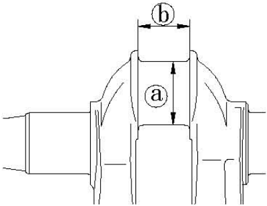
Főtengelycsap átmérője @: 23.969~23.984mm
Főtengelycsap szélessége: 21.0~21.1mm
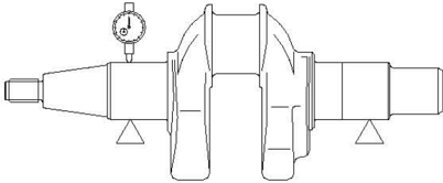
Főtengely ütési határértéke: 0.01mm
- Helyezzen műanyag hézagmérő szálat a forgattyúcsapra, a főtengellyel párhuzamosan.
Olajhézag
- 2.Szerelje a hajtórudat a forgattyúcsapra.
- 3.Húzza meg a hajtórúd csavarjait az előírt nyomatékkal.
Meghúzási nyomaték:
Első lépcső
- 5Nm
Második lépcső
9Nm
- 4.Távolítsa el a hajtórudat, és mérje meg az összenyomott műanyag hézagmérő szál szélességét. Ha nem felel meg az előírásnak, cserélje ki a hajtórudat.
Olajhézag: 0. 016~0. 046mm
Megjegyzés:
A mérés befejezéséig ne forgassa a hajtórudat.
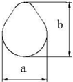
Szelepemelő
- Ellenőrizze a szelepemelő kopását és sérülését. Szükség esetén cserélje ki.
- 2.Mérje meg a szelepemelő külső átmérőjét. Ha nem felel meg az előírásnak, cserélje ki. Szelepemelő külső átmérője: 7.9650mm
Olajszóró fogaskerék
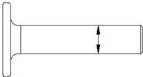
Vizsgálja meg az olajszóró fogaskerékegységet; nehézkes mozgás, kopás, sérülés vagy repedés esetén cserélje ki.
Főtengelycsapágy
Vizsgálja meg a csapágyat; kipattogzás vagy morgó hang esetén cserélje ki.
MEGJEGYZÉS:
Csak akkor távolítsa el a csapágyat, ha ki is cseréli.
Olajtömítésház
- Vizsgálja meg az O-gyűrű repedését és sérülését. Szükség esetén cserélje ki.
- Vizsgálja meg az olajtömítésház repedését és sérülését. Szükség esetén cserélje ki.
Forgattyúház és forgattyúházfedél
- Vizsgálja meg a forgattyúház fedelét. Repedés vagy sérülés esetén cserélje ki.
- 2.Vizsgálja meg a hűtővízjárat szennyeződését és eltömődését. Szükség esetén tisztítsa meg.
Teljes összeszerelés
Dugattyú és hajtórúd összeszerelése
Szerelje össze a dugattyút, a hajtórudat, a dugattyúcsapszeget és annak biztosítógyűrűjét.
MEGJEGYZÉS:
Beszereléskor ügyeljen arra, hogy a hajtórúd jelölése a dugattyútető jelölésével azonos oldalra kerüljön.
Használjon új dugattyúcsapszeg-biztosítógyűrűt. A biztosítógyűrű nyílása ne essen egy vonalba a biztosítógyűrű-horony nyílásával.
Dugattyúgyűrű beszerelése
- Szerelje fel az olajlehúzó gyűrűt, a 2. gyűrűt és a felső gyűrűt.
MEGJEGYZÉS:
A 2. gyűrű beszerelésekor a jelölés a dugattyútető felé nézzen.
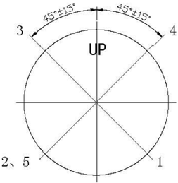
- A dugattyúgyűrűk véghézagának ábrája
Olajlehúzó gyűrű véghézaga 2 (feszítőgyűrű)
Olajlehúzó gyűrű véghézaga 1 (alsó sín)
Olajlehúzó gyűrű véghézaga 3 (felső sín)
A 2. dugattyúgyűrű véghézaga 4
Felső dugattyúgyűrű véghézaga 5

Dugattyú beszerelése
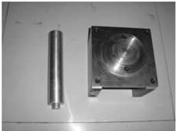
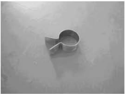
Dugattyú-bevezetővel szerelje be a dugattyút, és ügyeljen arra, hogy a dugattyútető „Up” jelölése a lendkerék felé nézzen.
MEGJEGYZÉS:
Beszereléskor kenje be motorolajjal a dugattyút és a dugattyúgyűrű oldalát.
Olajtömítésház beszerelése
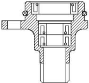
- Olajtömítés-beütő szerszámmal szerelje be a 10.8x21x7 olajtömítéseket (2 darab).
- Olajtömítés-beütő szerszámmal szerelje be a B20 X 30 X 7 olajtömítéseket.
MEGJEGYZÉS:
- ① Beszerelés előtt kenje be zsírral az új tömítést.
- ② Ügyeljen az olajtömítés rugójának ábrán jelzett irányára.
Főtengely beszerelése
- Célszerszámokkal szerelje a főtengelycsapágyat a forgattyúházba (csapágycsere esetén). Szerelje be az olajtömítést.
Házcsapágy-beütő
MEGJEGYZÉS:
A csapágy gyártói jelölése a lendkerék felé nézzen. Beszereléskor kenje be motorolajjal az új olajtömítést.
- Szerelje be a főtengelyt a forgattyúházba.
- Szerelje fel a hajtórúdfedelet, és húzza meg a hajtórúd csavarját az előírt nyomatékkal. Előírt nyomaték: 12 Nm
MEGJEGYZÉS:
- 1.Szerelje be a szelepemelőt.
Beszerelés előtt kenje be motorolajjal a mozgó alkatrészeket.
Vezérműtengely beszerelése
- Szerelje be a vezérműtengelyt. A vezérműtengely fogaskerekének jelölése essen egy vonalba a vezérműtengely vezérlőfogaskerekének jelölésével.
MEGJEGYZÉS:
Ház olajtömítésének beütője
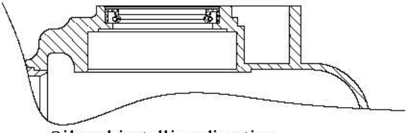
Olajtömítés beszerelési iránya
Beszerelés előtt kenje be motorolajjal a mozgó alkatrészeket.
- Szerelje be az olajtömítésházat.
Forgattyúházfedél beszerelése
- Szerelje be az olajszóró fogaskerékegységet.
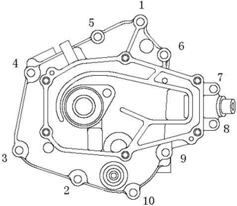
- Szerelje fel a forgattyúház fedelét, és az ábra szerint két lépcsőben húzza meg a csavarokat.
Meghúzási nyomaték:
Meghúzás 1: 5Nm
Meghúzás 2: 11 Nm
MEGJEGYZÉS:
Beszerelés előtt kenje be motorolajjal a mozgó alkatrészeket.
Felső egység
Felső motorburkolat
Robbantott ábra
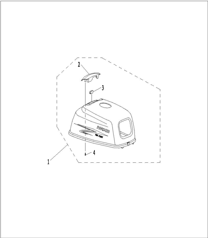
| Sorszám | Alkatrészszám | Leírás | Mennyiség | Megjegyzések |
|---|---|---|---|---|
| 1 | F2.6-06000001 | FELSŐ MOTORBURKOLAT | 1 | |
| 2 | F2.6-06000002 | SZÍVÓHANGTOMPÍTÓ | 1 | |
| 3 | F2.6-06000003 | Szívóhangtompító csillapítóeleme | 1 | |
| 4 | GB/T845-85 | Önmetsző csavar ST3.8x12 | 2 |
Szétszerelés és ellenőrzés
- Távolítsa el a szívóhangtompító csavarját.
- Távolítsa el a szívóhangtompítót és csillapítóbetétjét.
- Vizsgálja meg a felső motorburkolat, a szívóhangtompító és a csillapítóbetét repedését és sérülését. Szükség esetén cserélje ki.
Alsó motorburkolat
Robbantott ábra
Szétszerelés és ellenőrzés
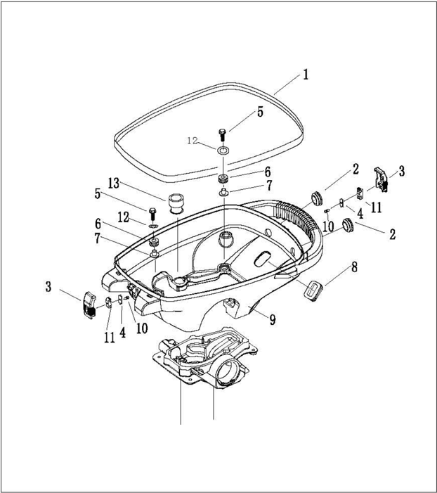
| Sorszám | Alkatrészszám | Leírás | Mennyiség | Megjegyzések |
|---|---|---|---|---|
| 1 | F2.6-05000002 | ALSÓ MOTORBURKOLAT TÖMÍTÉSE | 1 | |
| 2 | F2.6-05000004 | KEREK GUMIDUGÓ | 2 | |
| 3 | F2.6-05000008 | RETESZELŐKAMPÓ | 2 | |
| 4 | F2.6-05000010 | FÉM ÖSSZEKÖTŐRÚD | 2 | |
| 5 | GB/T5783-2000 | Csavar M6X25 | 4 | |
| 6 | F2.6-05000006 | Csillapítóelem | 4 | |
| 7 | F2.6-05000007 | Karimás távtartócső | 4 | |
| 8 | F2.6-05000003 | NÉGYSZÖGLETES GUMIDUGÓ | 1 | |
| 9 | F2.6-05000001 | ALSÓ MOTORBURKOLAT | 1 | |
| 10 | GB/T845-85 | Önmetsző csavar ST2.9x5 | 2 | |
| 11 | F2.6-05000009 | ÖSSZEKÖTŐRÚD | 2 | |
| 12 | GB/T96-85 | Alátét 6 | 4 | |
| 13 | F2.6-05000005 | Olajleeresztő gumihüvelye | 1 |
- Távolítsa el az alsó motorburkolat tömítését.
- Távolítsa el a felső motorburkolat reteszelőkampóját.
- Távolítsa el a kerek és a négyszögletes gumidugót.
- Vizsgálja meg az alsó motorburkolat repedését és sérülését. Szükség esetén cserélje ki.
- Vizsgálja meg a felső motorburkolat reteszelőkampójának repedését és sérülését. Szükség esetén cserélje ki.
Kormánykar
Robbantott ábra
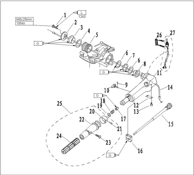
| Sorszám | Alkatrészszám | Leírás | Mennyiség | Megjegyzések |
|---|---|---|---|---|
| 1 | CB/T5783-2000 | Csavar M8x25 | ||
| 2 | F4-01000014 | KORMÁNYKAR FEDELE | ||
| 3 | F4-01000008 | KARPERSELY B | ||
| 4 | F4-01000011 | PERSELYALÁTÉT A | ||
| 5 | F4-05000014 | Kormánykar csillapítóegysége | ||
| 6 | F4-01000010 | PERSELYALÁTÉT B | ||
| 7 | F4-01000012 | HULLÁMOS PERSELY | ||
| 8 | F4-01000009 | KARPERSELY A | ||
| 9 | CB/T91-86 | Sasszeg Φ1.6x12 | ||
| 10 | F4-01090200 | SÚRLÓDÁSÁLLÍTÓ CSAVAR |
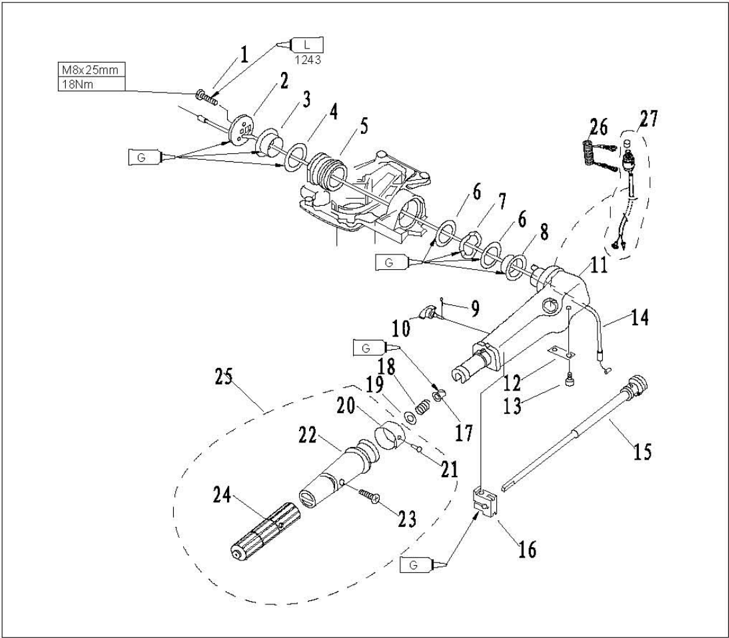
| Sorszám | Alkatrészszám | Leírás | Mennyiség | Megjegyzések |
|---|---|---|---|---|
| 11 | F4-01090001 | Kormánykar | 1 | |
| 12 | F4-01090002 | Gázkar támasza | 1 | |
| 13 | GB/T818-85 | M5x12 FÉLGÖMBFEJŰ CSAVAR | 2 | |
| 14 | F2.6-02010003 | GÁZBOWDEN-EGYSÉG | 1 | |
| 15 | F4-01090100 | GÁZKAREGYSÉG | 1 | |
| 16 | F4-01090003 | SÚRLÓDÓELEM | 1 | |
| 17 | F4-01090006 | PERSELY | 1 | |
| 18 | F4-01090007 | RUGÓ | 1 | |
| 19 | GB/T848-85 | 10 ALÁTÉT | 1 | |
| 20 | F4-01090303 | GÁZÁLLÁSJELZŐ | 1 | |
| 21 | GB/T827-86 | Φ2x5 SZEGECS | 1 | |
| 22 | T15-01020301 | FOGANTYÚ MŰANYAG FEDELE | 1 | |
| 23 | GB/T820-85 | Süllyesztett fejű csavar M5x24 | 1 | |
| 24 | T15-01020302 | FOGANTYÚ GUMIBORÍTÁSA | 1 | |
| 25 | T15-01020300 | Kormánykar-markolategység | 1 | |
| 26 | F4-01090401 | Motorleállító biztonsági zsinóregység | 1 | |
| 27 | F2.6-02010200 | MOTORLEÁLLÍTÓ KAPCSOLÓEGYSÉG | 1 |
Szétszerelés és ellenőrzés
- Távolítsa el a kormánykar fedelét.
- 2.Távolítsa el a kar perselyét, a perselyalátétet és a hullámos alátétet.
- Távolítsa el a kormánykar csillapítóegységét.
- Távolítsa el a súrlódásállító csavart.
- Távolítsa el a kormánykart.
- Távolítsa el a gázbowdent.
- Távolítsa el a gázkar támaszát és a gázkart.
- Távolítsa el a motorleállító kapcsolót.
- Vizsgálja meg a kormánykar repedését és sérülését. Szükség esetén cserélje ki.
- Szükség esetén.
- Vizsgálja meg a kormánykar csillapítóelemének repedését és sérülését. Szükség esetén cserélje ki.
- Vizsgálja meg a gázbowden repedését és sérülését. Szükség esetén cserélje ki.
- Vizsgálja meg a motorleállító kapcsoló vezetőképességét. Ha nem felel meg az előírásnak, cserélje ki.
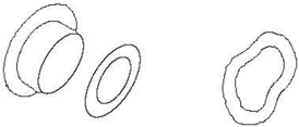
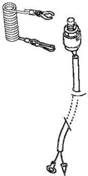
Rögzítőlemez eltávolítva:
Vezet
Rögzítőlemez beszerelve:
Nem vezet
Leállítókapcsoló gombja megnyomva: vezet
Tartókonzol
Robbantott ábra
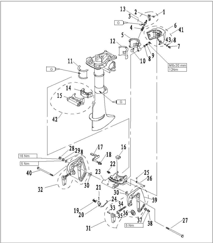
| Sorszám | Alkatrészszám | Leírás | Mennyiség | Megjegyzések |
|---|---|---|---|---|
| 1 | CB/T875-86 | SZEGECS 4x11 | 1 | |
| 2 | F4-01060002 | SZORÍTÓFOGANTYÚ | 1 | |
| 3 | F2.6-01050101 | RETESZELŐCSAVAR | 1 | |
| 4 | F2.6-01050002 | RUGÓ | 1 | |
| 5 | F2.6-01050001 | FORGÓKONZOL FEDELE | 1 | |
| 6 | F2.6-00000101 | KONZOLFEDÉL | 1 | |
| 7 | CB/T818-2000 | FÉLGÖMBFEJŰ CSAVAR M6x16 | 2 | |
| 8 | CB/T97.1-85 | Alátét 6 | 6 | |
| 9 | CB/T5783-2000 | Csavar M6x30 | 4 | |
| 10 | F2.6-01050200 | RETESZELŐBLOKK-EGYSÉG | 1 | |
| 11 | F2.6-01000003 | PERSELY A | 1 | |
| 12 | F2.6-01000004 | PERSELY B | 1 | |
| 13 | F2.6-01050100 | RETESZELŐKAR-EGYSÉG | 1 | |
| 14 | F2.6-01040100 | CSILLAPÍTÓELEM | 1 |
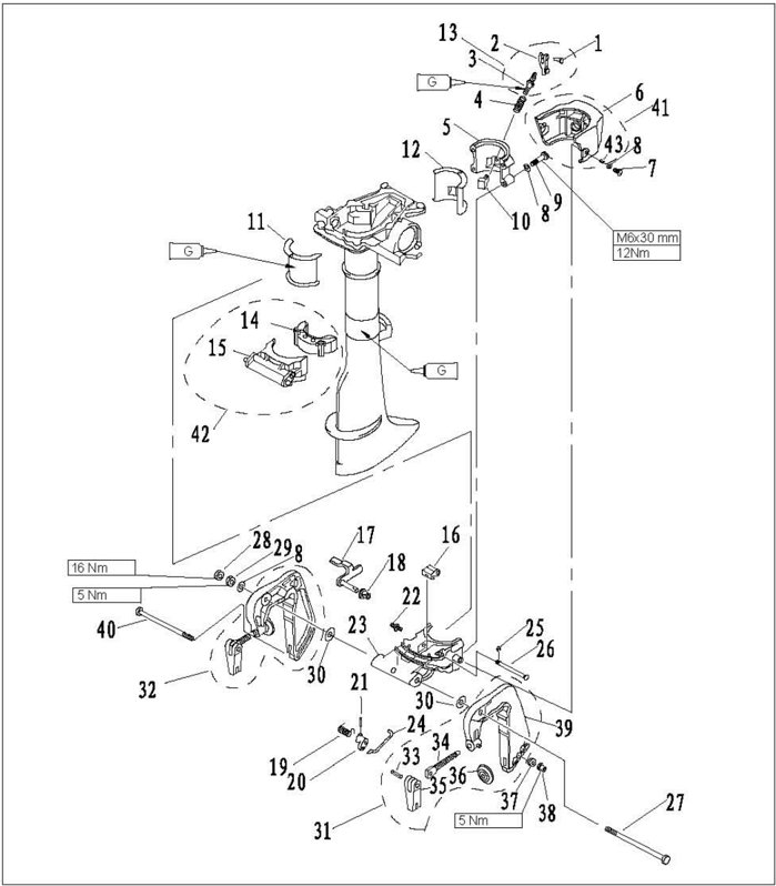
| Sorszám | Alkatrészszám | Leírás | Mennyiség | Megjegyzések |
|---|---|---|---|---|
| 15 | F2.6-01040001 | TÁMASZTÓKONZOL | 1 | |
| 16 | F2.6-01030007 | KAR | 1 | |
| 17 | F2.6-01030100 | BILLENTÉS SZORÍTÓKAR-EGYSÉGE | 1 | |
| 18 | F4-01090006 | PERSELY | 1 | |
| 19 | F2.6-01030003 | RUGÓ | 1 | |
| 20 | F2.6-01030004 | BILLENTÉS RETESZELŐKARJA | 1 | |
| 21 | CB/T879.2-200 | Csap 2x10 | 1 | |
| 22 | GB/T7940.1-95 | ZSÍRZÓSZEM M6 | 1 | |
| 23 | F2.6-01030001 | FORGÓKONZOL | 1 | |
| 24 | F2.6-01030005 | BILLENTÉS RETESZELŐRÚDJA | 1 | |
| 25 | GB/T896-86 | KAPOCS 3.5 | 1 | |
| 26 | F2.6-01030006 | CSAP | 1 | |
| 27 | F2.6-01000001 | Csavar M8x135 | 1 | |
| 28 | CB/T6172.1-85 | Anya M8 | 1 |
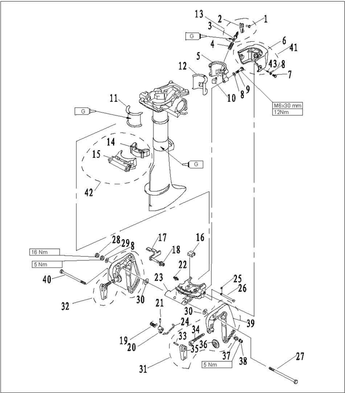
| Sorszám | Alkatrészszám | Leírás | Mennyiség | Megjegyzések |
|---|---|---|---|---|
| 29 | CB/T6170-85 | Anya M8 | 1 | |
| 30 | CB/T96-1985 | Alátét 8 | 2 | |
| 31 | F2.6-01010000 | BAL KONZOLEGYSÉG | 1 | |
| 32 | F2.6-01020000 | JOBB KONZOLEGYSÉG | 1 | |
| 33 | F4-01010005 | SZEGECS | 2 | |
| 34 | F4-01010002 | SZORÍTÓCSAVAR | 2 | |
| 35 | F4-01010004 | HAJÓOLDALI SZORÍTÓFOGANTYÚ | 2 | |
| 36 | F4-01010003 | SZORÍTÓLEMEZ | 2 | |
| 37 | F2.6-01000002 | CSAVARPERSELY | 1 | |
| 38 | GB/T889.1-2000 | M6 ANYA | 1 | |
| 39 | F2.6-01010001 | SZORÍTÓKONZOL (BAL) | 1 | |
| 40 | CB/T5782-2000 | Csavar M6x125 | 1 | |
| 41 | F2.6-00000100 | KONZOLFEDÉL-EGYSÉG | 1 | |
| 42 | F2.6-01040000 | TÁMASZTÓEGYSÉG | 1 | |
| 43 | F2.6-00000102 | PERSELY | 1 |
Szétszerelés és ellenőrzés
- 1.Távolítsa el a szorítófogantyút és a konzolfedelet.
- 2.Távolítsa el a forgókonzol fedelét.
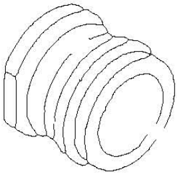
- 3.Távolítsa el a forgókonzol perselyét és csillapítóelemét.
- 4.Távolítsa el a szorítókonzolt.
- 5.Távolítsa el a forgókonzolt.
- 6.Távolítsa el a billentés szorítófogantyúját és reteszelőkarját.
- Vizsgálja meg a forgókonzol és a szorítókonzol sérülését és repedését. Szükség esetén cserélje ki.
- Vizsgálja meg a forgókonzol perselyének és csillapítóelemének sérülését és repedését. Szükség esetén cserélje ki.
- Vizsgálja meg a billentés szorítófogantyújának és reteszelőkarjának alakváltozását és sérülését. Szükség esetén cserélje ki.
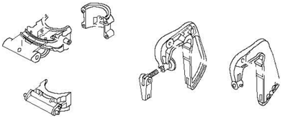


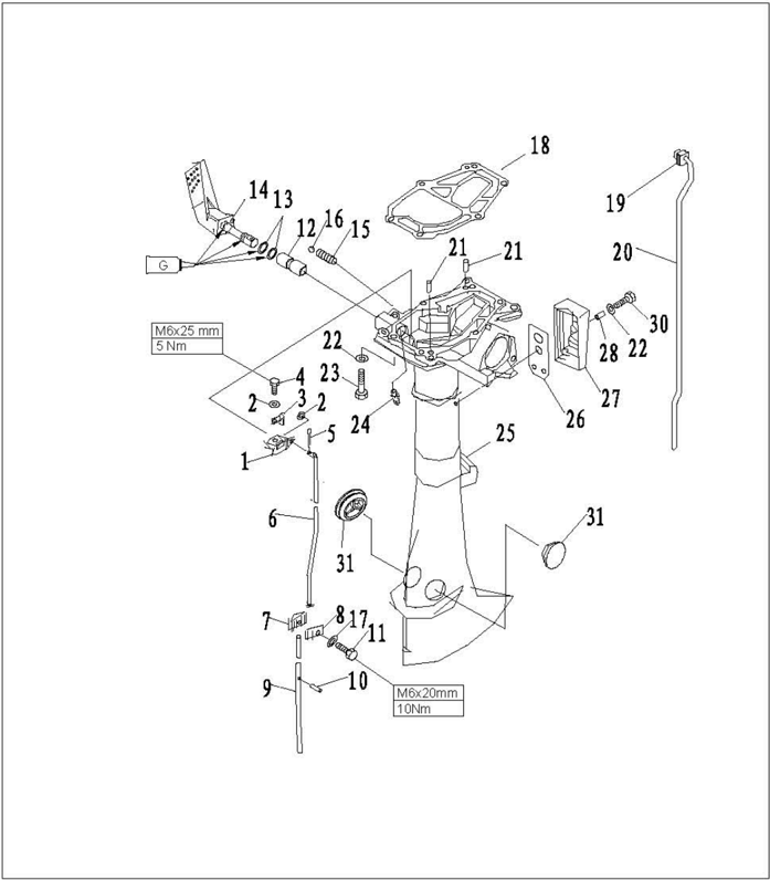
Felső egység robbantott ábrája
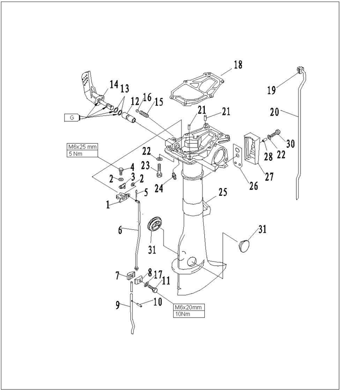
| Sorszám | Alkatrészszám | Leírás | Mennyiség | Megjegyzések |
|---|---|---|---|---|
| 1 | F2.6-02000006 | VÁLTÓRÚD KARJA | 1 | |
| 2 | GB/T97.1-85 | Alátét 5 | 3 | |
| 3 | F2. 6-02000008 | VÁLTÓRÚD KARJÁNAK ALÁTÉTJE | ||
| 4 | GB/T5783-2000 | Csavar M5x12 | 1 | |
| 5 | GB/T91-86 | Sasszeg 1.6x12 | 1 | |
| 6 | F2.6-02000007 | VÁLTÓRÚD | 1 | |
| 7 | F2.6-00000001 | VÁLTÓRÚD CSATLAKOZÓJA A | 1 | |
| 8 | F2.6-00000002 | VÁLTÓRÚD CSATLAKOZÓJA B | ||
| 9 | F2.6-03000005 | VÁLTÓBÜTYÖK-TENGELY | 1 | |
| 10 | GB/T879.2-2000 | Csap 2.5x14 | 1 | |
| 11 | GB/T5783-2000 | Csavar M6x20 | 1 | |
| 12 | F4-02000002 | Váltórúdkar perselye | 1 | |
| 13 | JISB2401 | O-gyűrű P9 | 2 | |
| 14 | F2.6-02020000 | SEBESSÉGVÁLTÓKAR-EGYSÉG | 1 |
| Sorszám | Alkatrészszám | Leírás | Mennyiség | Megjegyzések |
|---|---|---|---|---|
| 15 | F4-02000003 | SEBESSÉGVÁLTÓ RUGÓJA | 1 | |
| 16 | GB308-84 | Acélgolyó 8 | 1 | |
| 17 | F4-00000005 | ALÁTÉT | 1 | |
| 18 | F2.6-00000003 | MOTORTÖMÍTÉS | 1 | |
| 19 | F4-02040002 | I ALAKÚ GUMISZALAG | 1 | |
| 20 | F2.6-02000003 | VÍZCSŐ | 1 | |
| 21 | F15-0000013 | Csap 4x12 | 2 | |
| 22 | CB/T97.1-85 | Alátét 6 | 7 | |
| 23 | CB/T5783-2000 | Csavar M6x35 | 6 | |
| 24 | CB/T7940.1-95 | ZSÍRZÓSZEM M6 | 1 | |
| 25 | F2.6-02000001 | FELSŐ HÁZ | 1 | |
| 26 | F2.6-02000005 | KIPUFOGÓFEDÉL TÖMÍTÉSE | 1 | |
| 27 | F2.6-02000004 | KIPUFOGÓFEDÉL | 1 | |
| 28 | F2.6-00000102 | PERSELY | 1 |
Szétszerelés és ellenőrzés
| Sorszám | Alkatrészszám | Leírás | Mennyiség | Megjegyzések |
|---|---|---|---|---|
| 29 | CB/T818-2000 | Félgömbfejű csavar M6x16 | ||
| 30 | F4-02000012 | FELSŐ GUMIDUGÓ | 2 |
- 1.Távolítsa el a vízcsövet.
- 2.Távolítsa el a sebességváltókar-egységet.
- 3.Távolítsa el a váltórudat és a váltórúd karját.
- 4.Távolítsa el a kipufogófedelet.
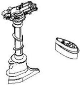
- Ellenőrizze a felső ház repedését és kopását. Szükség esetén cserélje ki.
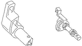
- 6.Ellenőrizze a sebességváltókar kopását és sérülését. Szükség esetén cserélje ki.
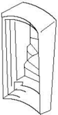
- 7.Ellenőrizze a kipufogófedél repedését és kopását. Szükség esetén cserélje ki.
Alsó egység
Vízszivattyú-egység
Robbantott ábra
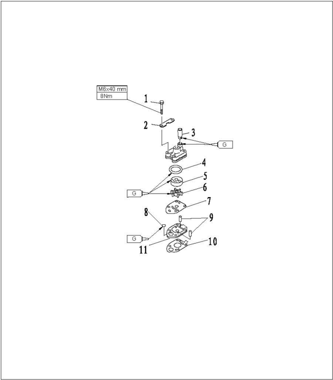
| Sorszám | Alkatrészszám | Leírás | Mennyiség | Megjegyzések |
|---|---|---|---|---|
| 1 | CB/T5783-2000 | Csavar M6x40 | 4 | |
| 2 | F2.6-03000016 | VÍZSZIVATTYÚ RÖGZÍTŐLEMEZE | 2 | |
| 3 | F4-03000021 | VÍZSZIVATTYÚ GUMICSÖVE | 1 | |
| 4 | JASO 19-033 | O-gyűrű | 1 | |
| 5 | F2.6-03000015 | VÍZSZIVATTYÚ BELSŐ HÁZA | 1 | |
| 6 | F2.6-03000100 | JÁRÓKERÉKEGYSÉG | ||
| 7 | F2.6-03000010 | KÜLSŐ LEMEZ | 1 | |
| 8 | F2.6-03000009 | O-gyűrű | 1 | |
| 9 | F4-03000013 | Csap Φ4x18 | 2 | |
| 10 | F2.6-03000007 | VÍZSZIVATTYÚ TÖMÍTÉSE | 1 | |
| 11 | F2.6-03000008 | VÍZSZIVATTYÚHÁZ | 1 |
Szétszerelés és ellenőrzés
- Távolítsa el a vízszivattyú rögzítőlemezét.
- Távolítsa el a vízszivattyú házát.
- Távolítsa el a járókereket, a belső házat és a vízszivattyú belső házának O-gyűrűjét.
- Távolítsa el a vízszivattyú alapját.
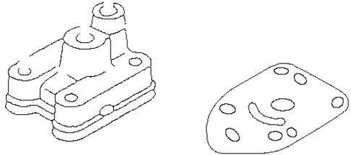
- Ellenőrizze a vízszivattyúház és a külső lemez repedését, elhajlását és sérülését. Szükség esetén cserélje ki.
- Ellenőrizze a vízszivattyú belső házának és járókerekének repedését, alakváltozását, égésnyomait és sérülését. Szükség esetén cserélje ki.
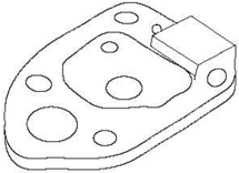
- 7.Ellenőrizze a vízszivattyú alapjának repedését, elhajlását, karcolását és sérülését. Szükség esetén cserélje ki.

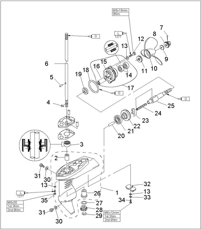
Alsó egység robbantott ábrája
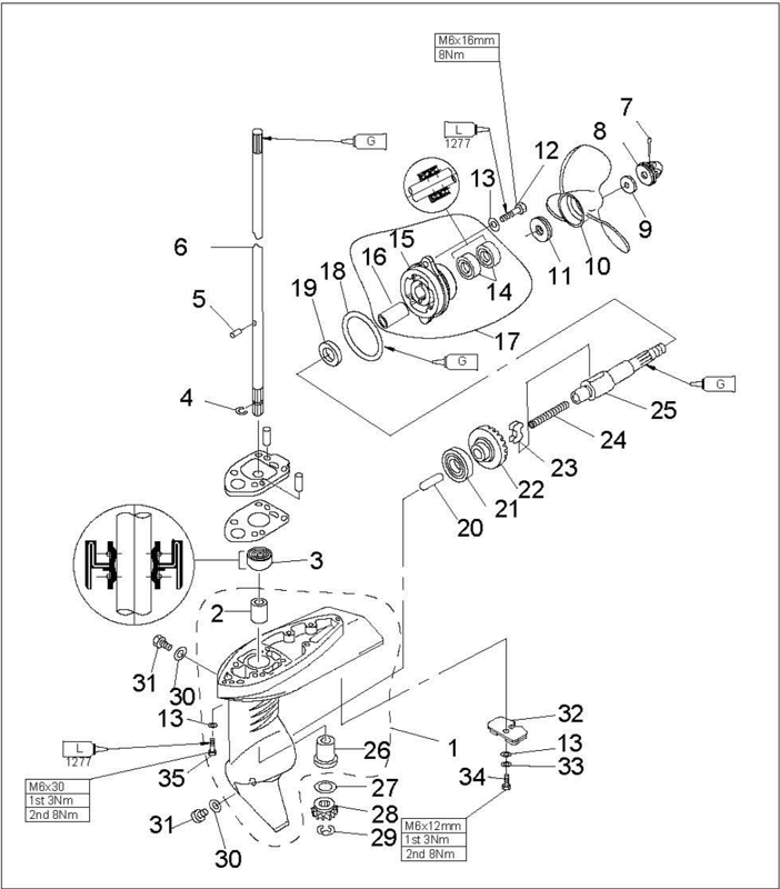
| Sorszám | Alkatrészszám | Leírás | Mennyiség | Megjegyzések |
|---|---|---|---|---|
| 1 | F2.6-03000001 | ALSÓ HÁZ | 1 | |
| 2 | F2.6-03000003 | CSAPÁGY | 1 | |
| 3 | F2.6-03000004 | OLAJTÖMÍTÉS 9.8x24x9 | 1 | |
| 4 | F2.6-03000012 | KAPOCS | 1 | |
| 5 | F2.6-03000013 | Csap Φ3.5x7 | 1 | |
| 6 | F2.6-03000011 | HAJTÓTENGELY | 1 | |
| 7 | GB/T91-86 | Sasszeg 2.5x30 | 1 | |
| 8 | F4-03080000 | ANYAEGYSÉG | 1 | |
| 9 | F4-03000026 | ALÁTÉT | 1 | |
| 10 | F2.6-03010000 | HAJÓCSAVAREGYSÉG | 1 | |
| 11 | F4-03000025 | TÁVTARTÓ | 1 | |
| 12 | GB/T5783-2000 | Csavar M6x16 | 2 | |
| 13 | GB/T97.1-85 | Alátét 6 | 2 | |
| 14 | F4-03050002 | OLAJTÖMÍTÉS 13x22x7 | 2 |
| Sorszám | Alkatrészszám | Leírás | Mennyiség | Megjegyzések |
|---|---|---|---|---|
| 15 | F2.6-03000301 | ALSÓ HÁZ FEDELE | 1 | |
| 16 | F2.6-03000302 | SIKLÓCSAPÁGY | 1 | |
| 17 | F2.6-03000300 | ALSÓ HÁZ FEDÉLEGYSÉGE | 1 | |
| 18 | JISB2401 P48 | O-gyűrű Φ47.1x3.5 | 1 | |
| 19 | F2.6-03000021 | ALÁTÉT | 1 | |
| 20 | F2.6-03000020 | VÁLTÓDUGÓ | 1 | |
| 21 | NTN6003EY | GOLYÓSCSAPÁGY | 1 | |
| 22 | F2.6-03000019 | ELŐREMENETI FOGASKERÉKEGYSÉG | 1 | |
| 23 | F2.6-03000202 | KAPCSOLÓBLOKK | 1 | |
| 24 | F4-03030003 | KAPCSOLÓBLOKK RUGÓJA | 1 | |
| 25 | F2.6-030000201 | HAJÓCSAVARTENGELY | 1 | |
| 26 | F2.6-03000002 | CSAPÁGY | 1 | |
| 27 | F2.6-03000017 | Hézagoló alátét (T: 2.0 mm) | 1 | |
| 28 | F2.6-03000018 | HAJTÓFOGASKERÉK | 1 |
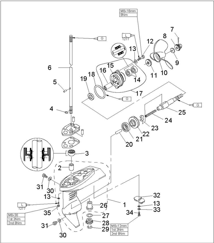
| Sorszám | Alkatrészszám | Leírás | Mennyiség | Megjegyzések |
|---|---|---|---|---|
| 29 | CB/T896-86 | BIZTOSÍTÓGYŰRŰ 6 | ||
| 30 | F4-03000024 | TÖMÍTÉS | ||
| 31 | F4-03000023 | OLAJNYÍLÁS DUGÓJA | ||
| 32 | F4-03000022 | ANÓD | ||
| 33 | CB/T861.1-87 | BELSŐ FOGAZÁSÚ ALÁTÉT 6 | ||
| 34 | CB/T5783-2000 | Csavar M6x12 | ||
| 35 | CB/T5783-2000 | Csavar M6x30 |
Szétszerelés és ellenőrzés
- Távolítsa el a sasszeget, az anyaegységet és a távtartót.
- 2.Távolítsa el a hajócsavaregységet és a távtartót.
- 3.Távolítsa el az alsó ház fedelét.
- Távolítsa el a hajtótengelyt, az előremeneti fogaskerékegységet és a váltódugót.
- 5.Távolítsa el a váltórúd bütyökegységét és a hajtótengelyt.
- Távolítsa el a védőlemezes siklócsapágyat.
- Siklócsapágy-beütő szerszámmal távolítsa el a védőlemez nélküli siklócsapágyat.
- 8.Távolítsa el a kapcsolóblokkot a hajócsavartengelyről.
Hajócsavartengely és kapcsolóblokk
- Ellenőrizze a kapcsolóblokk kopását és sérülését. Szükség esetén cserélje ki.
- Ellenőrizze a hajócsavartengely kopását és sérülését. Szükség esetén cserélje ki.
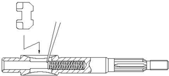
Kapcsolóblokk beszerelése
- Helyezze a kapcsolóblokk rugóját a hajócsavartengely végén lévő furatba.
- 2.Szerelje be a kapcsolóblokkot az ábra szerint. Ügyeljen az irányára.
Alsó ház fedele
- Ellenőrizze a csapágy rozsdásodását és működés közbeni morgó hangját. Szükség esetén cserélje ki.
- Csapágylehúzóval távolítsa el a csapágyat és az olajtömítést.
Megjegyzés:
Csak akkor távolítsa el a csapágyat, ha ki is cseréli.
- Puha kefével és oldószerrel tisztítsa meg a házfedelet.
- Ellenőrizze a házfedél repedését és sérülését. Szükség esetén cserélje ki.
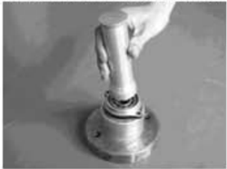
Szerelje be az olajtömítést.
Megjegyzés:
Az olajtömítés és a csapágy beszereléséhez használjon célszerszámot.
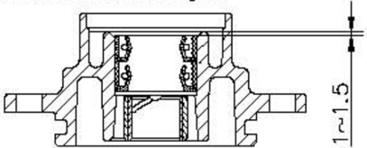
Siklócsapágy
Hajtótengely
Vizsgálja meg a hajtótengely elhajlását és kopását. Szükség esetén cserélje ki.
Fogaskerék
Előremeneti fogaskerék csapágya
Vizsgálja meg a csapágy rozsdásodását és forgás közbeni morgó hangját. Szükség esetén cserélje ki.
Alsó egység háza
- Vizsgálja meg az alsó házfedél repedését és sérülését. Ellenőrizze a hűtővíz-beömlő eltömődését. Szükség esetén cserélje ki.
- Szerszámok.
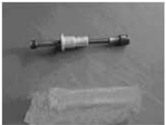
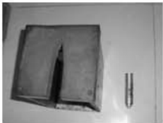
Védőlemezes siklócsapágy beütőszerszáma
Alsó háztámasz és védőlemez nélküli siklócsapágy beütőszerszáma
- 3.Szereljen be új olajtömítést az ábrán jelzett mélységig. (Mértékegység: mm)
Vizsgálja meg a védőlemezes és a védőlemez nélküli siklócsapágy kopását, repedését és sérülését. Szükség esetén cserélje ki.

Alsó házfedél olajtömítésének és csapágyának beszerelése

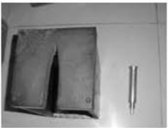
Alsó háztámasz és hajtótengely-olajtömítés beütőszerszáma
Gyakori hibák és megoldásuk
| Hiba típusa | Lehetséges ok | Elhárítási művelet |
|---|---|---|
| Az indító nem működik | Az indító alkatrészei hibásak | Javítsa meg vagy cserélje ki |
| A motor nem indul (az indító működik) | Az üzemanyagtartály üres; az üzemanyag szennyezett vagy elöregedett | Töltse fel a tartályt tiszta, friss üzemanyaggal |
| A motor nem indul (az indító működik) | A szellőzőcsavar nincs meglazítva | Lazítsa meg a szellőzőcsavart |
| A motor nem indul (az indító működik) | A gyújtógyertya/gyújtógyertyák szennyezettek vagy nem megfelelő típusúak | Vizsgálja meg a gyújtógyertyát/gyújtógyertyákat. Tisztítsa meg vagy cserélje az ajánlott típusra |
| A motor nem indul (az indító működik) | A gyertyapipa/gyertyapipák helytelenül vannak felszerelve | Ellenőrizze és szerelje fel újra a pipát/pipákat |
| A motor nem indul (az indító működik) | A gyújtás vezetékei sérültek vagy rosszul csatlakoznak | Ellenőrizze a vezetékek kopását és szakadását. Húzza meg az összes laza csatlakozást. Cserélje ki a kopott vagy szakadt vezetékeket |
| A motor nem indul (az indító működik) | A gyújtás alkatrészei hibásak | Cserélje ki |
| A motor nem indul (az indító működik) | A motorleállító kapcsoló zsinórja nincs csatlakoztatva | Csatlakoztassa a zsinórt |
| A motor nem indul (az indító működik) | A motor belső alkatrészei sérültek | Javítsa meg |
| A motor nem indul (az indító működik) | A szelephézag helytelen | Ellenőrizze és állítsa be az előírás szerint |
| A motor egyenetlenül jár alapjáraton vagy leáll | A gyújtógyertya/gyújtógyertyák szennyezettek vagy nem megfelelő típusúak | Vizsgálja meg a gyújtógyertyát/gyújtógyertyákat. Tisztítsa meg vagy cserélje az ajánlott típusra |
| A motor egyenetlenül jár alapjáraton vagy leáll | Az üzemanyagrendszer eltömődött | Ellenőrizze, nincs-e becsípődve vagy megtörve az üzemanyagvezeték, illetve nincs-e más akadály az üzemanyagrendszerben |
| A motor egyenetlenül jár alapjáraton vagy leáll | Az üzemanyag szennyezett vagy elöregedett | Töltse fel a tartályt tiszta, friss üzemanyaggal |
| A motor egyenetlenül jár alapjáraton vagy leáll | A gyertyahézag helytelen | Ellenőrizze és állítsa be az előírás szerint |
| A motor egyenetlenül jár alapjáraton vagy leáll | A gyújtás vezetékei sérültek vagy rosszul csatlakoznak | Ellenőrizze a vezetékek kopását és szakadását. Húzza meg az összes laza csatlakozást. Cserélje ki a kopott vagy szakadt vezetékeket |
| A motor egyenetlenül jár alapjáraton vagy leáll | Nem az előírt motorolajat használják | Ellenőrizze és cserélje ki az olajat az előírás szerint |
| A motor egyenetlenül jár alapjáraton vagy leáll | A termosztát hibás vagy eltömődött | Cserélje ki |
| A motor egyenetlenül jár alapjáraton vagy leáll | A karburátor beállításai helytelenek | Cserélje ki |
| A motor egyenetlenül jár alapjáraton vagy leáll | Az üzemanyagtartály szellőzőcsavarja zárva van | Lazítsa meg a szellőzőcsavart |
| A motor egyenetlenül jár alapjáraton vagy leáll | A gázbowden beállítása helytelen | Állítsa be megfelelően |
| A motor egyenetlenül jár alapjáraton vagy leáll | A szívatógomb ki van húzva | Állítsa vissza alaphelyzetbe |
| A motor egyenetlenül jár alapjáraton vagy leáll | A motor szöge túl nagy | Állítsa vissza normál üzemi helyzetbe |
| A motor teljesítménye csökken | A hajócsavar sérült | Javítsa meg vagy cserélje ki a hajócsavart |
| A motor teljesítménye csökken | A trimmszög helytelen | Állítsa be a trimmszöget a leghatékonyabb üzem eléréséhez |
| A motor teljesítménye csökken | A motor a fartükrön helytelen magasságban van felszerelve | Állítsa be a motort a megfelelő fartükörmagasságra |
| A motor teljesítménye csökken | A hajó fenekén vízi élőlényekből álló lerakódás van | Tisztítsa meg a hajó fenekét |
| A motor teljesítménye csökken | Vízinövények vagy más idegen anyag tekeredett a hajtóműházra | Távolítsa el az idegen anyagot, és tisztítsa meg az alsó egységet |
| A motor teljesítménye csökken | Az üzemanyagrendszer eltömődött | Ellenőrizze, nincs-e becsípődve vagy megtörve az üzemanyagvezeték, illetve nincs-e más akadály az üzemanyagrendszerben |
| A motor teljesítménye csökken | Az üzemanyag szennyezett vagy elöregedett | Töltse fel a tartályt tiszta, friss üzemanyaggal |
| A motor teljesítménye csökken | A gyertyahézag helytelen | Ellenőrizze és állítsa be az előírás szerint |
| A motor teljesítménye csökken | A gyújtás vezetékei sérültek vagy rosszul csatlakoznak | Ellenőrizze a vezetékek kopását és szakadását. Húzza meg az összes laza csatlakozást. Cserélje ki a kopott vagy szakadt vezetékeket |
| A motor teljesítménye csökken | A gyújtás alkatrészei meghibásodtak | Cserélje ki |
| A motor teljesítménye csökken | Nem az előírt motorolajat használják, vagy túl sok olajat töltöttek be | Ellenőrizze és cserélje ki az olajat az előírás szerint, vagy állítsa be a motorolajszintet az előírt szintre |
| A motor teljesítménye csökken | A termosztát hibás | Cserélje ki |
| A motor teljesítménye csökken | Az üzemanyag-csatlakozás helytelen | Csatlakoztassa megfelelően |
| A motor teljesítménye csökken | Nem az előírt gyújtógyertyát/gyújtógyertyákat használják | Ellenőrizze és cserélje ki a gyújtógyertyát/gyújtógyertyákat az előírás szerint |
| A motor túlzottan rezeg | A hajócsavar sérült | Javítsa meg vagy cserélje ki a hajócsavart |
| A motor túlzottan rezeg | A hajócsavartengely sérült | Cserélje ki |
| A motor túlzottan rezeg | Vízinövények vagy más idegen anyag tekeredett a hajócsavarra | Távolítsa el az idegen anyagot, és tisztítsa meg a hajócsavart |
| A motor túlzottan rezeg | A motor rögzítőcsavarja laza | Húzza meg a csavart |
| A motor túlzottan rezeg | A kormánycsap laza | Húzza meg a kormánycsapot |
| A motor túlzottan rezeg | A kormánycsap sérült | Cserélje ki |