
Parsun F20/F25 Outboard Engine Service Manual
Table of Contents
- General Information
- Explosive Drawing and Symbol
- Specifications
- Periodic Service
- Recoil Starter
- Ignition System
- Fuel System (Detailed)
- Power Unit (Detailed)
- Upper Unit
- Lower Unit
- Common Troubles and Solutions
General Information
Identification
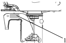
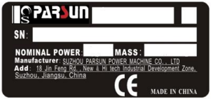
The outboard motor serial number is marked on the label. The label can be found on the bracket left assembly or on the upper part of the bracket swivel. Record your outboard motor serial number in the spaces provided to assist you in ordering spare parts from your Parsun dealer or for reference in case your outboard motor is stolen.
1
- Outboard motor serial number location

Serial number as follows :
SN
MOTOR BATCH SEQUENCE NUMBER
PRODUCTION CODE
Propeller Selection
The performance of your outboard motor will be critically affected by your choice of propeller, as an incorrect choice could adversely affect performance.
For a greater boat load and a low engine speed, a smaller-pitch propeller is more suitable. Conversely, a large-pitch propeller is more suitable for a smaller operating load as it enables the correct engine speed to be maintained.
When the engine is running at full throttle position, the suitable propeller should be used according to the engine's RPM and the fuel capability. So the outboard engine can supply the best performance.
| Propeller sizes | Material |
|---|---|
| 3-9 " 8 7 ×8 | Aluminum alloy |
| 3-9 " 8 7 ×9 | Aluminum alloy |
| 3-9 " 8 7 ×10 " 2 1 | Aluminum alloy |
| 3-9 " 8 7 ×11 " 4 1 | Aluminum alloy |
| 3-9 " 8 7 ×12 | Aluminum alloy |
| 3-9 " 8 7 ×13 | Aluminum alloy |
| 3-9 " 8 7 ×14 | Aluminum alloy |
Emergency Start
If the starting device is not working, the engine can be started by emergency start cable.
WARNING:
- The start program can only be used in emergency and to return to harbor for repairing.
- When you start the engine by emergency start cable, the start-in-gear protection device is not working. So please ensure the shift rod is in NEUTRAL position.
- Please ensure nobody standing behind you in case the cable is pulled out to hurt people.
- After the engine starts up, don't fit the start device or top cowling. Put clothing or other items far away. Don't touch flywheel or other moving parts.
- When starting and operating, don't touch ignition coil, spark plug cap or other electric parts.
The procedure is as follows:
- Remove the top cowling.
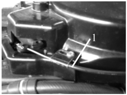
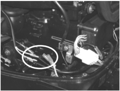
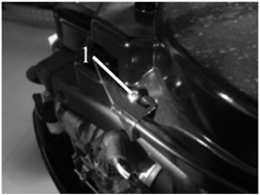
- Remove the start-in-gear protection device cable.
- Start-in-gear protection device cable
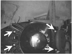
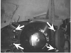
- Demount three bolts, break the alarm light and remove starter.
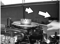
- I nsert the knot of the cable in the notch of flywheel rotor, and wind the cable around flywheel several rounds in clockwise direction..
- Pull the manual starter handle slowly until you feel resistance.
- Give a strong pull to start the engine. Repeat if necessary.
Safety While Working
To prevent the danger or accidents when performing maintenance and repair, and improve the work efficiency, please obey the following safety procedures.
1. Fire Prevention
Gasoline (petrol), lubricant and grease are highly flammable. While working, keep away from heat, sparks and open flames.
2. Ventilation
Petroleum vapor and engine exhaust gases are violent in toxicity. They are harmful to breathe and deadly if inhaled in large quantities. When test-running an engine indoors, maintain good ventilation.
3. Self-Protection
Protect your eyes with suitable safety glasses or safety goggles, when drilling, grinding or operating air compressor. Protect hands and feet by wearing protective work clothes, safety gloves and shoes if necessary.
4. Lubricants and Sealing Fluids
When performing maintenance procedures and repair to Parsun outboards, use only products provided or recommended by our Company.
Under normal conditions of use, there should be no hazards from the use of the lubricants mentioned in this manual, but safety is all-important, and by adopting good safety practices, any risk is minimized.
- 1 To protect the skin, the application of a suitable barrier cream to the hands before working is recommended.
- 2 Clothing which has become contaminated with lubricants should be changed as soon as practicable, and washed before further use.
- 3 Avoid skin contact with lubricants.
- 4 Hands and any other part of the body which have been in contact with lubricants or lubricant-contaminated clothing, should be thoroughly washed with hot water and soap as soon as practicable.
- 5 A supply of clean lint-free cloths should be available for wiping run-off lubricants or grease.
5. Good Working Practices
- 1 Follow the tightening torque instruction. When tightening bolts, nuts and screws, tighten the large sizes first, and tighten inner-positioned fixings before outer-positioned ones.
- 2 Use the recommended special tools to protect parts from damage. Use the right tool in the right manner.
Disassembly and Assembly
When disassembly and assembly, please follow the following principles
- Use special tools when disassembling and assembling.
- Clean dirt before disassembling the parts.
- Oil the contact surfaces of moving parts before assembly.
- Install bearing with the manufacturer's markings on the stipulated side and liberally oil the bearing.
- When installing oil seals, apply a light coating of water-resistant grease to the ledge and outside diameter.
- After assembly, check if the moving parts operate normally.
One-Time Use Parts
One-time use parts are gasket, oil seal, O-ring, cotter pin and spring ring, and etc.. When re-assembling outboard engine, you must change the one-time use parts.
Pre-Delivery Check
To ensure the using, please inspect the following before delivery.
- CHECKING FUEL SYSTEM Check if the fuel pipe is connected firmly, and if the fuel tank is filled with fuel.
CAUTION:
Do not use pre-mixed fuel for this 4-stoke outboard engine.
2. Checking Oil Level
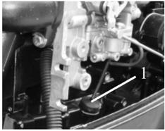
- 1 Check the engine oil level Remove oil rule, check engine oil level..
Oil rule 2. High position mark 3. Low position mark
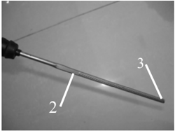
Ensure the oil level between the marks of upper and lower. If above upper level, drain engine oil; if below lower mark, add engine oil up to upper level.
- 2 Check the gear oil level so, install the oil level plug and tighten it according to specified torque. Otherwise please add
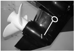
Remove the oil level plug. Check if the gear oil overflows at the oil level checking hole. If gear oil.
- Oil level plug
3. Check Steering System
Check if steering is stable.
Check if steering friction is adjusted correctly. Turn clamp handle screw clockwise to increase resistance.
Turn clamp handle screw counter clockwise to Lower resistance. 1. Clamp handle screw
4. Check Shift Lever and Throttle
Check if the shift lever is operated smoothly.
Check if the throttle grip is turned smoothly from full closed position to full open position.
5. Check Engine Stop Switch Assembly
Check if the engine stops when pushing the engine stop switch assembly or pulling out the stopper hang rope.
6. Check Cooling Water Checking Hole
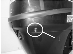
When the engine is running, check if cooling water overflows at the cooling water checking hole.
- Cooling water checking hole
7. Breaking-In Running
- 1 Initial 1 hour: operate the engine at 2000 r/min or about a half throttle.
- ② The second hour: operate the engine at 3000 r/min or about 3/4 throttle.
- ③ The following 8 hours: operate the engine at full throttle continuously. Each operation time doesn't exceed 5 minutes.
8. Inspection After Breaking-In Running
- 1 Check if gear oil contains water.
- ② Check if the fuel line leaks.
- ③ After breaking-in running, operate the engine at idling speed. Use cleaning tool to wash over the cooling water passage by fresh water.
9. After Breaking-In Running, Inspect Idling Speed
- ① Preheating engine for 5 minutes.
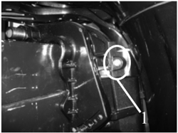
- ② Using the tachometer to measure idling speed RPM. If out of specification, adjust it. Idling speed: 925~1025 r/min.
- ③ Turn the throttle stop screw clockwise or counter clockwise until the specified idling speed is attained. 1.Throttle anchoring screw
- ④ After adjusting idling speed, picking up RPM several times to check the engine's stability.
Special Tools and Detection Device
When performing maintenance and repair, you need to use all kinds of special tools and detection device. The use of correct tools will improve the work efficiency and avoid of the damage to the people and outboard engines.
Special Tools
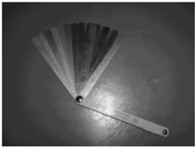
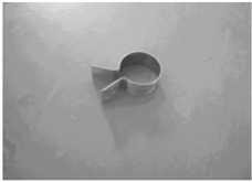
Clearance gauge Piston slider
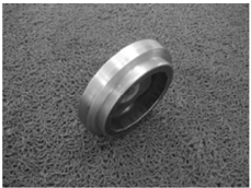
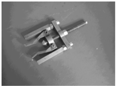
Oil cleaner spanner Bearing puller
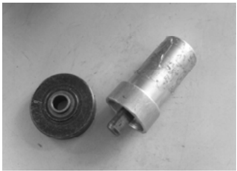
Lower casing cover bearing installer
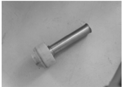
Lower casing cover assy. installer
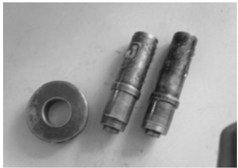
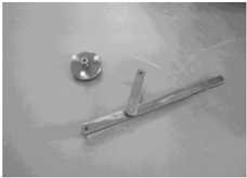
Flywheel gripper and puller
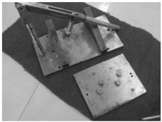
Valve spring compressor
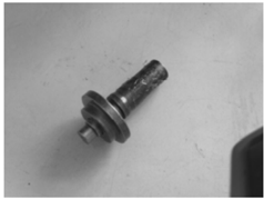
Lower casing cover oil seal installer Lower casing cover needle bearing installer
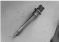
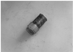
Lower casing needle bearing installer Drive shaft bearing housing installer
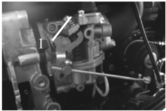
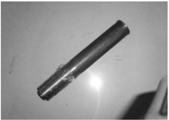
Drive shaft bearing installer Bearing block oil seal installer
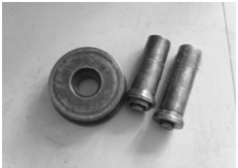
Forward gear bearing housing installer
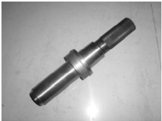
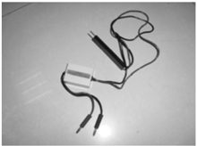
Detection Device
Back gear bearing installer
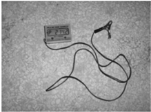
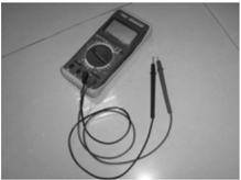
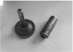
Digital tachometer Digital multimeter Peak voltage adaptor
Explosive Drawing and Symbol
Explosive Drawing
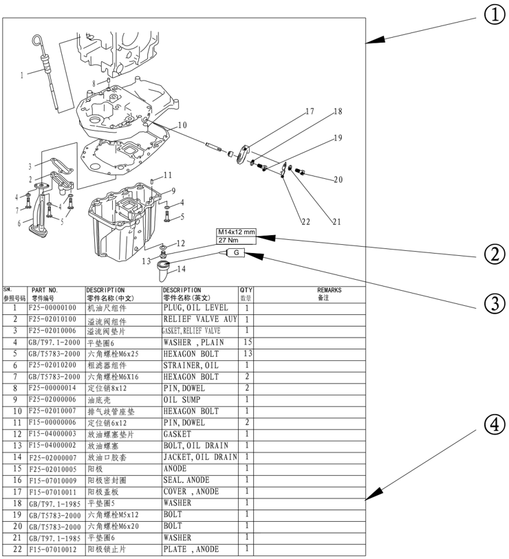
- ① Parts explosive drawing.
- ② Screw specification and specified torque.
- ③ Oil, fluid sealant or locking substance daubing point.
- ④ Spare parts details.
Symbol
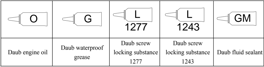
Specifications
Outboard Engine Specifications
| Item | Item | Item | Description | Item | Item | Description |
|---|---|---|---|---|---|---|
| Overall length (BM/FW) | Overall length (BM/FW) | 1151/703mm | Ignition system | C.D.I | ||
| Overall width (BM/FW) | Overall width (BM/FW) | 430/376mm | Enrichment system | Initial enrichment | ||
| Overall height | S | 1153mm | Spark plug | DPR7EA-9 | ||
| Overall height | L | 1280mm | Exhaust system | Through propeller wheel hub | ||
| Transom height | S | 381mm | Lubrication system | Pressure lubrication | ||
| Transom height | L | 508mm | Fuel type | Unleaded regular gasoline | ||
| S (BM/FW) | S (BM/FW) | 66/68kg | Fuel standard | PON86 | ||
| L (BM/FW) | L (BM/FW) | 68/70kg | Recommended engine oil | API: SE, SF, SG, SH, SJ SAE: 10W30, 10W40 | ||
| Max output | F20 | 14.7Kw@5500 r/min | Engine oil quantity (Before changing oil cleaner) | 1.7L | ||
| Max output | F25 | 18.4Kw@5500 r/min | Engine oil quantity (Before changing oil cleaner) | 1.7L | ||
| Full throttle operation | Full throttle operation | 5000 6000 r/min | Recommended gear oil | Hypoid gear oil SAE ﹟ 90 | ||
| Max fuel | F20 | 7.3L/h@6000 r/min | ||||
| consumption | F25 | 9.2L/h@6000 r/min | Gear oil quantity | 320 cm3 | ||
| Idle speed Neutral | Idle speed Neutral | 975±50 r/min | Tilt angle | 8 o 12 o 16 o , 20 o , 24 o | ||
| Type | Type | 4 stroke, OHC | Tilt-up angle | 64 o | ||
| Number of cylinders | Number of cylinders | 2 | Steering angle | 45 o +45 o | ||
| Displacement | Displacement | 498cm³ | Gear positions | F-N-R | ||
| Bore×Stroke | Bore×Stroke | 65mm×75mm | Gear ratio | 2.08 | ||
| Compression ratio | Compression ratio | 9.87:1 | Gear type | Spiral bevel gear | ||
| Min. compression pressure | Min. compression pressure | 810kPa | Clutch type | Dog clutch | ||
| Lubricant pressure | Lubricant pressure | 80kPa (Idle speed) | Propeller drive system | Spline | ||
| Number of carburetor | Number of carburetor | 1 | Propeller direction | Clockwise (back view) |
| Control system | Tiller control (BM) Romote control (FW) |
|---|---|
| Start system | Recoil start (BM) Electric start (FW) |
Maintenance Information
Power unit
| Item | Item | Item | Description | Item | Description | |
|---|---|---|---|---|---|---|
| Cylinder head | Warp limit | Warp limit | 0.1mm | Valve clearance | Intake | 0.15~0.25mm |
| Cylinder head | Camshaft inside diameter | Camshaft inside diameter | 37.000~37.025mm | (cold) | Exhaust | 0.25~0.35mm |
| Cylinder head | Rocker shaft outside diameter | Rocker shaft outside diameter | 15.971~15.991mm | Face width | Intake | 1.84~2.97mm |
| Cylinder head | Rocker inside diameter | Rocker inside diameter | 16.000~16.018mm | Face width | Exhaust | 1.98~3.11mm |
| Cylinder | Bore | Bore | 65.00~65.015mm 65.1mm | width | Intake | 0.9~1.1mm |
| Cylinder | Wear limit | Wear limit | Exhaust | 0.9~1.1mm | ||
| Cylinder | Taper limit | Taper limit | 0.08mm | Margin thickness | Intake | 0.8mm |
| Cylinder | Out of round limit | Out of round limit | 0.05mm | Margin thickness | Exhaust | 0.9mm |
| Piston | Piston diameter | Piston diameter | 64.950~64.965mm Valve | Head diameter | Intake | 31.9~32.1mm |
| Piston | Measuring point height | Measuring point height | 2mm from the bottom of piston | Head diameter | Exhaust | 25.9~26.1mm |
| Piston | Piston-to-cylinder clearance | Piston-to-cylinder clearance | 0.035~0.065mm | Stem diameter | Intake | 5.475~5.490mm |
| Piston | Pin boss inside diameter | Pin boss inside diameter | 15.974~15.985mm | Stem diameter | Exhaust | 5.460~5.475mm |
| Piston pin outside diameter | Piston pin outside diameter | Piston pin outside diameter | 15.965~15.970mm | Guide inside diameter | Intake | 5.500~5.512mm |
| Piston ring | Top ring | Thickness | 1.17~1.19mm | Guide inside diameter | Exhaust | 5.500~5.512mm |
| Piston ring | Breadth | 2.25~2.4mm | Stem to guide clearance | Stem to guide clearance | 0.025~0.052mm | |
| Piston ring | End gap | 0.15~0.30mm | Stem roundness limit | Stem roundness limit | 0.03mm | |
| Piston ring | Side clearance | 0.02~0.06mm | Free length | Free length | 40.0mm | |
| Piston ring | Thickness | 1.47~1.49mm Valve spring | Free length limit | Free length limit | 38.4mm | |
| Piston ring | ring | Breadth | 2.60~2.80mm | Tilt limit | Tilt limit | 1.7mm |
| Piston ring | 2nd | End gap | 0.30~0.50mm od | Small end inside diameter. | Small end inside diameter. | 15.985~15.998mm |
| Piston ring | Side clearance | 0.02~0.06mm Connecting | Big end inside diameter. | Big end inside diameter. | 36.000~36.016mm | |
| Piston ring | ring | Thickness | 2.36~2.48mm | Big end oil clearance | Big end oil clearance | 0.020~0.052mm |
| Piston ring | Oil | Breadth | 2.75mm | Big end | A: Black | 1.496~1.490mm |
| End gap | 0.20~0.70mm | bearing thickness | B: Brown | 1.490~1.484mm | ||
|---|---|---|---|---|---|---|
| Side clearance | 0.04~0.18mm | Journal diameter | Journal diameter | 42.984~43.000mm | ||
| Height | Intake | 30.834~31.034mm | Crankpin diamete | Crankpin diamete | 32.984~33.000mm | |
| Exhaust | 30.834~31.034mm | Crankpin width | Crankpin width | 21.00~21.07mm | ||
| Round diameter | Round diameter | 25.90~26.10mm | Big end side clearance | Big end side clearance | 0.05~0.22mm | |
| Journal | Top | 36.925~36.945mm | Round limit | Round limit | 0.05mm | |
| diamete | Middle | 36.935~36.955mm | Thermostat | Opening temperature | Opening temperature | 58~62ºC |
| Round limit | Round limit | 0.03mm | Thermostat | Full-opening temperature | Full-opening temperature | 70ºC |
| Journal oil clearance | Journal oil clearance | 0.050~0.090mm | Thermostat | Valve lift height | Valve lift height | 3mm |
| Type | Type | Gerotor pump | Fuel pump | Displacement | Displacement | 70L@3000 r/min |
| Safety valve opening pressure | Safety valve opening pressure | 382~442 kPa | Fuel pump | Pressure | Pressure | 49kPa |
| Outside rotor to housing clearance | Outside rotor to housing clearance | 0.09~0.15mm | Fuel pump | Plunger lift | Plunger lift | 5.85~9.65mm |
| Outside rotor to inside rotor clearance | Outside rotor to inside rotor clearance | 0.12mm | Crankcase | Journal oil clearance | Journal oil clearance | 0.012~0.044mm |
| Rotor to cover | Rotor to cover | 0.03~0.08mm | Crankcase | Journal bearing | A: Black | 1.500~1.494mm |
| clearance | clearance | 0.03~0.08mm | Crankcase | clearance | B: Brown | 1.494~1.488mm |
Lower Unit
| Item | Item | Description | Item | Item | Description |
|---|---|---|---|---|---|
| Gear Clearance | Drive gear to forwarder gear | 0.30~0.72mm | Gear Clearance | Forwarder gear shim | 1.0, 1.1, 1.2, 1.3, 1.4mm |
| Gear Clearance | Drive gear to back gear | 0.92~1.65mm | Gear Clearance | Back gear shim | 1.0, 1.1, 1.2, 1.3mm |
| Gear Clearance | Drive gear shim | 0.7, 1.0, 1.1, 1.2, 1.3, 1.4, 1.5, 1.6mm | Gear Clearance |
Electric System
Ignition and Ignition Control System
| Item | Item | Description | Item | Item | Description |
|---|---|---|---|---|---|
| Ignition timing | Idle speed | BTDC 8.5º | Charge coil peak voltage | 1500 r/min (load) | 291V |
| Ignition timing | 6000 r/min | BTDC 30º | Charge coil peak voltage | 3500 r/min (load) | 294V |
| Spark plug gap | Spark plug gap | 0.8~0.9mm | Charge coil resistance | Charge coil resistance | 644.4~787.6 Ω |
|---|---|---|---|---|---|
| Ignition coil resistance | Primary coil | 0.27~0.33 Ω | Power spool output peak voltage | Start (no-load) | 24V |
| Ignition coil resistance | Secondary coil (including high voltage cap resistance) | 11.17~13.53 K Ω | Power spool output peak voltage | 1500 r/min (no-load) | 31V |
| CDI output peak voltage | Start (load) | 264V | Power spool output peak voltage | 3500 r/min (no-load) | 71V |
| CDI output peak voltage | 1500 r/min | 265V | Power spool output peak voltage | Start (load) | 23V |
| CDI output peak voltage | 3500 r/min | 270V | Power spool output peak voltage | 1500 r/min (load) | 31V |
| Start (no-load) | 12V | Power spool output peak voltage | 3500 r/min (load) | 70V | |
| Start (load) | 12V | Power spool resistance | Power spool resistance | 6.9~8.5 Ω | |
| 1500 r/min (load) | 12V | Light coil output | Start (no-load) | 40V | |
| 3500 r/min (load) | 12.4V | Light coil output | 1500 r/min (no-load) | 54V | |
| Pulsed coil resistance * | Pulsed coil resistance * | 265~396 Ω | Light coil output | 3500 r/min (no-load) | 110V |
| Charge coil peak voltage | Start (no-load) | 294V | Light coil resistance | Light coil resistance | 0.9~1.1 Ω |
| Charge coil peak voltage | Start (load) | 291V |
Enrichment Control System
| Item | Description |
|---|---|
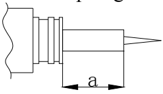
| Initial enrichment plunger length *1 | 10.7~15.4mm |
| Initial enrichment resistance *2 | 17.7~18.7 Ω |
( *1 ) The data is for reference only. ( *2 ) Measurement condition: Initial enrichment plunger length =10.7mm The data is for reference only.
Tightening Torque
Specified Torque
| Part to be tightened | Part to be tightened | Part name | Thread size | Quantity | Torque |
|---|---|---|---|---|---|
| Spark plug | - | M12 | 1 | 17 Nm | |
| Flywheel | Nut | M20 | 1 | 150 Nm | |
| Carburetor installation | Bolt | M6 | 2 | 8 Nm | |
| Carburetor bracket | Bolt | M6 | 3 | 8 Nm |
| 1st tightening | Bolt | M9 | 6 | 23Nm | |
|---|---|---|---|---|---|
| 2nd tightening | Bolt | M9 | 6 | 46 Nm | |
| 1st tightening | Bolt | M6 | 3 | 6 Nm | |
| 2nd tightening | Bolt | M9 | 6 | 12 Nm | |
| Oil cleaner | Oil cleaner | - | - | 1 | 18 Nm |
| Oil cleaner stud | Oil cleaner stud | - | - | 1 | 40 Nm |
| Locknut (rocker arm) | Locknut (rocker arm) | Nut | M6x0.75 | 4 | 14 Nm |
| Power unit assembling | Power unit assembling | Bolt | M8 | 8 | 21 Nm |
| 1st tightening | Bolt | M6 | 7 | 6 Nm | |
| 2nd tightening | Bolt | M6 | 7 | 12 Nm | |
| Thermostat cover | Thermostat cover | Bolt | M6 | 2 | 7Nm |
| 1st tightening | Bolt | M8 | 6 | 15 Nm | |
| 2nd tightening | Bolt | M8 | 6 | 30 Nm | |
| 1st tightening | Bolt | M6 | 6 | 6 Nm | |
| 2nd tightening | Bolt | M6 | 6 | 12 Nm | |
| Connecting rod | 1st tightening | Bolt | M6 | 4 | 6 Nm |
| Connecting rod | 2nd tightening | Bolt | M6 | 4 | 17 Nm |
| Driven belt pulley | Driven belt pulley | Bolt | M10 | 1 | 38 Nm |
| Lower unit mounting | Lower unit mounting | Bolt | M10 | 4 | 37 Nm |
| Lower unit housing cover | Lower unit housing cover | Bolt | M6 | 2 | 11Nm |
| Water inlet | Water inlet | Bolt | M5 | 2 | 4 Nm |
| Oil drain bolt | Oil drain bolt | Bolt | - | 1 | 9 Nm |
| Oil inspection hole | Oil inspection hole | Bolt | - | 1 | 9 Nm |
| Pinion | Pinion | Nut | M10 | 1 | 50 Nm |
| Propeller nut | Propeller nut | Nut | M14 | 1 | 34 Nm |
| Steering handle | Steering handle | Nut | M10 | 1 | 10 Nm |
| Steering handle | Steering handle | Self-locking nut | M10 | 1 | 22 Nm |
| Exhaust manifold | Exhaust manifold | Bolt | M6 | 3 | 10 Nm |
| Throttle grip | Throttle grip | Bolt | M5 | 1 | 3 Nm |
| Shift lever bracket | Shift lever bracket | Bolt | M6 | 4 | 10 Nm |
| Shift leaf spring | Shift leaf spring | Bolt | M6 | 1 | 10 Nm |
| Bottom cowling small strap | Bottom cowling small strap | Bolt | M6 | 2 | 10 Nm |
| Clamp bracket | Clamp bracket | Self-locking nut | - | 2 | 45 Nm |
| Oil drain bolt | Oil drain bolt | Bolt | M14 | 1 | 27 Nm |
| Part to be tightened | Part name | Thread size | Quantity | Torque |
|---|---|---|---|---|
| Ignition coil | Bolt | M6 | 2 | 8 Nm |
| CDI assembly | Bolt | M6 | 2 | 5 Nm |
| CDI assembly bracket | Bolt | M6 | 2 | 5 Nm |
| Stator coil | Bolt | M5 | 3 | 6 Nm |
| Pulsed coil | Bolt | M5 | 2 | 5 Nm |
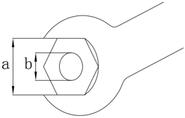
General Torque
| Nut (a) | Bolt (b) | Torque |
|---|---|---|
| 8mm | M5 | 5Nm |
| 10mm | M6 | 8 Nm |
| 12mm | M8 | 18 Nm |
| 14mm | M10 | 36 Nm |
| 17mm | M12 | 43 Nm |
Periodic Service
Maintenance Time Table
| Items | Contents | Initial maintenace | Initial maintenace | General maintenance period | General maintenance period |
|---|---|---|---|---|---|
| 10 hours (month | 50 hours (3 months) | 100 hours (6 months) | 200 hours (1 year) | ||
| Anode | Inspection/ replacement | ○ | ○ | ||
| Anode (Inner) | Inspection/ replacement | ○ | |||
| Cooling water passage | Cleaning | ○ | ○ | ||
| Spark plug | Cleaning/ adjustment / replacement | ○ | ○ | ||
| Grease points | Greasing | ○ | |||
| Fuel filter | Inspection/ replacement | ○ | ○ | ○ | |
| Fuel system | Inspection | ○ | ○ | ○ | |
| Fuel tank | Inspection/ cleaning | ○ | |||
| Idling speed | Inspection/ adjustment | ○ | ○ | ||
| Engine oil | Replacement | ○ | ○ | ||
| Oil cleaner | Replacement | ○ | |||
| Valve clearance (OHC | Inspection/ adjustment | ○ | ○ | ||
| Ignition timing | Inspection | ○ | ○ | ||
| Thermostat | Inspection | ○ | |||
| Gear oil | Replacement | ○ | ○ | ||
| Water pump | Inspection | ○ |
| Propeller and cotter pin | Inspection/ replacement | ○ | ○ | |
|---|---|---|---|---|
| Timing belt | Inspection/ replacement | ○ | ○ | |
| Throttle cable | Inspection/ adjustment | ○ | ||
| Shift lever/Shift cable | Inspection/ adjustment | ○ |
CAUTION:
After running the outboard engine in salt water, waste water or mud water, wash over the engine by fresh water immediately.
If using leaded gasoline frequently, check the valve and related components each 100 hours.
Timing belt should be changed every 1000 hours (5 years).
Fuel System
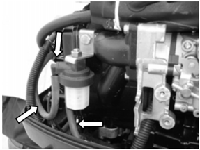
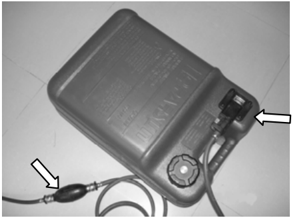
- CHECK FUEL TANK, CARBURETOR, FUEL PUMP AND FUEL PIPE Check if fuel tank, carburetor, fuel pump and fuel pipe are damaged or leaked. Replace if necessary.
Check if the fuel filter on the tank is dirty. Clean or replace if necessary.
2. Check Fuel Cock and Fuel Joint
Check if fuel cock and fuel joint are cracked, damaged or leaking. Replace if necessary.
3. Check Fuel Filter
Check if fuel filter is cracked, damaged or has dirt inside. If so, replace .
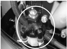
CAUTION:
Clean the spilled fuel.
Power Unit
Engine Oil Level
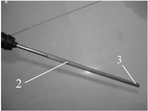
- Remove oil rule, check if the engine oil level is between the following marks of the upper and lower .
- If above the upper mark, drain the engine oil; if below lower mark, add engine oil up to upper mark.
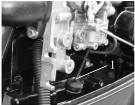
- Oil rule 2. High position mark 3. Low position mark
CAUTION:
Run the engine and then turn it off, wait for several minutes, and check the engine oil level by the oil rule again.
If the engine oil still not within the proper level, add/drain as needed.
Changing Engine Oil
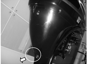
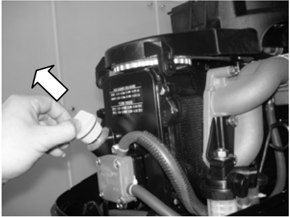
- Remove oil level plug, oil drain bolt and bolt gasket; drain off the engine oil.
- Install new bolt gasket; install oil drain bolt .
- Fill engine oil through oil filler hole. Engine oil quantity: 1.7 L (Before changing oil cleaner) 1.9 L (After changing oil cleaner ) Oil type: API: SE, SF, SG, SH, SJ or SAE: 10W30, 10W40
- Install oil level plug.
- Check engine oil level.
Valve Clearance
- Remove stopper hang rope from engine stop switch assy. Remove spark plug cap from spark plug.
- Remove starter and belt cover.
- Remove fuel pump and cylinder cover.
- Check if timing belt is slack, aging or damaged. Replace if necessary.
- Rotate the flywheel clockwise to make the mark '1' on driven pulley align with the mark '▼' on the cylinder head.
Check the clearance between the intake and exhaust valve of the upper cylinder. Adjust it if necessary.
- Rotate the flywheel clockwise to make the mark '2' on driven pulley align with the mark '▼' on the cylinder head.
Check the clearance between the intake and exhaust valve under the lower cylinder. Adjust it if necessary.
CAUTION:
Don't rotate the flywheel counter clockwise in case the valve system is damaged.
NOTE:
Adjust the valve clearance when the engine is cold .
| Valve clearance | Intake valve | 0.15~0.25mm |
|---|---|---|
| (cold position) | Exhaust valve | 0.25~0.35mm |
- Loose lock nut, rotate adjusting bolt to reach the specified valve clearance.
NOTE:
Rotate adjusting bolt clockwise to reduce the valve clearance.
Rotate adjusting bolt counter clockwise to increase the valve clearance.
- Re-assemble the spare parts.
Backward control:
- Turn the throttle grip to fully closed position.
- Check if the throttle cable is slack, if the throttle lever touches the throttle stop screw, or if the
1
Spark Plug
- Remove spark plug cap and spark plug.
- Clean off carbon build-up on the electrodes.
- Check if the electrodes are corroded or have deposit, or if the washer is damaged. If necessary, change the spark plug. Spark plug type: DPR7EA 9
- Inspect if the spark plug gap is within specification. If necessary, change the spark plug.
- Install spark plug. Use spark plug spanner to tighten it according to specified torque. Specified torque : 17 Nm
Control System
Throttle Grip
arresting stop on the throttle accelerograph enforce touches the check plate on the fixed bracket.
Check plate 2. Arresting stop
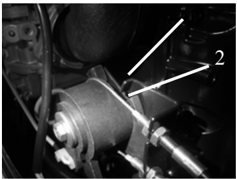
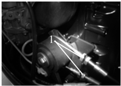
- Loosen the throttle cable adjusting screw, adjust the throttle cable position, and tighten throttle cable adjusting screw.
- Throttle cable stop screw
Forward control:
- Turn the gear shift lever to neutral position.
- Check if the arresting stop on the throttle accelerograph enforce touches the check plate on the bracket.
- Loosen the lock nut and take out the cotter pin, then remove the cable joint.
- Adjust the joint position to make the joint hole align with the pin on the throttle accelerograph enforce.
- Cotter pin 2. Cable joint 3. Lock nut
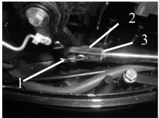
CAUTION:
The cable joint must be screwed in for over 8mm.
- Fit on the cotter pin and tighten the lock nut.
Shift Operation
Backward control:
When change from neutral to forward or reverse gear, check if the shift operation is smooth. If necessary, adjust the columned nut.
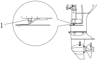
Forward control:
- When change from neutral to forward or reverse gear, check if the shift operation is smooth. If necessary, adjust the length of shift cable.
- Put the shift lever on the control box in neutral.
NOTE:
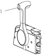
When the shift lever in neutral, check if the shift lever is in vertical to the engine's fitting surface.
Idling Speed
Check idling speed, and adjust it if necessary.
- Preheat engine for 5 minutes.
- Attach the tachometer to the spark plug wire to measure idling speed RPM. If out of specification, adjust it.
- Oolumned nut
Idling speed:
925~1025 r/min
- Shift lever
1
- Turn the throttle stop screw clockwise or counter clockwise, until the specified idling speed is attained.
NOTE:
Turn clockwise to increase idling speed. Turn counter clockwise to decrease idling speed. If necessary, turn the idling speed screw on the carburetor clockwise or counter clockwise, until the specified idling speed is attained.
CAUTION:
Before adjusting the idling speed, the throttle cable should be properly adjusted. After adjusting the idling speed, if necessary , you can adjust the throttle cable again .
Start-in-Gear Protection
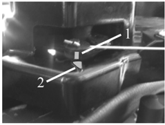
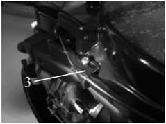
Set the shift lever in neutral, and check if the marking ' ▋' on the arrester pawl aligns with the marking ' ▼ ' of the starter case If necessary, adjust the mounted plate for the arrester tightwire, to align with the marking.
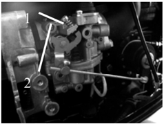
- Throttle stop screw
- Idling speed screw
- ' ▋ 'marking 2. ' ▼ 'marking 3. Mounted plate for the arrester tightwire
Lower Unit
Gear Oil
Check Gear Oil Level
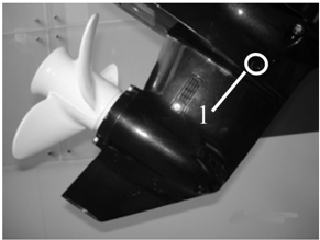
Remove the oil level plug screw. If the gear oil overflows, the oil level is correct; otherwise, add gear oil.
- Oil level plug screw
Changing Gear Oil
- Hold the outboard engine in an upright position.
- Place a container with enough capacity under the outboard engine.
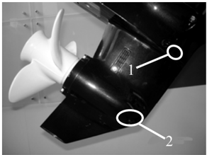
- Remove the oil drain screw, and remove the oil level plug screw, and then drain the gear oil..
- Add gear oil through the oil drain scew hole using pressure filling device.
- When gear oil overflows through the oil level plug hole, install the oil level plug screw.
- Oil level plug screw 2. Oil drain screw
- Install the oil drain screw, then clean overflowing gear oil.
NOTE:
Check the drained gear oil. If the gear oil is milky, check the oil seal. Replace the oil seal if necessary. If the gear oil contains metal chippings, check the gear and bearing.
CAUTION:
Must change oil drain bolt gasket each time.
Lower Unit Leakage Check
Connecting the leakage tester to the oil level plug hole to check for the lower unit leakage. If the pressure drops (pressure: 1kg/cm³), inspect the oil seal and components.
General Inspection
Anode
Inspect lower unit anode and engine anode (on the thermostat cover). Clean the greasy dirt and scales. If wear or damage is above 1/2, replace the anode.
CAUTION:
Cannot grease or paint the anode, or it will not operate properly
Grease Points
- Refer the illustration for greasing points. Paint the water resistant grease.
- Paint anti-corrosion grease on the propeller shaft.
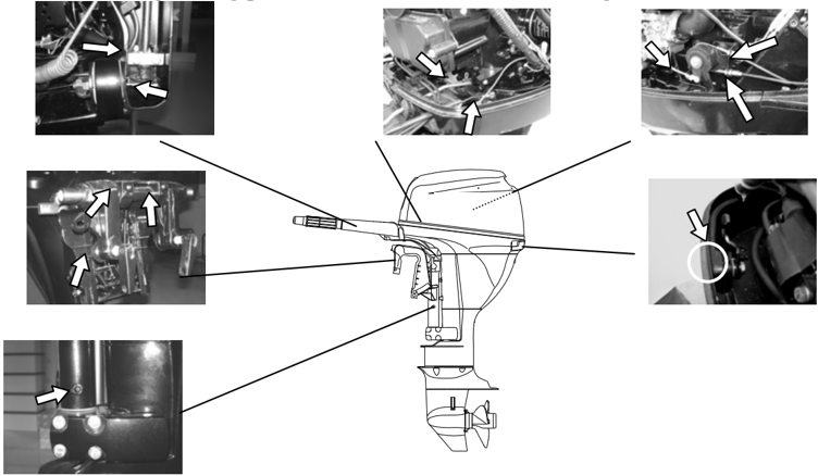
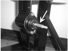
.
Cooling Water Passage
- Inspect cooling water passage, if blocked, clean it.
- Cooling water passage inlet
- Place the outboard engine in the water and ensure the water level is above the anti-vortex plate, then start the engine.
- Check if water overflows at the cooling water checking hole. If there is no flow or intermittent flow, check the cooling water passage.
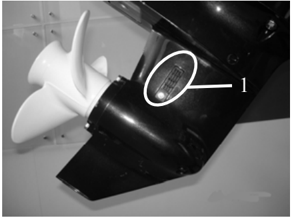
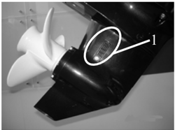
- Cooling water inlet 2. Cooling water checking hole
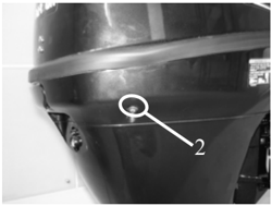
Thermostat
- Remove the thermostat cover and thermostat.
- Hang the thermostat in a container with water.
- Heat the container.
- Check the valve open height under the specified water temperatures. If out of order, change it.
- Fit on the thermostat and thermostat cover, then tighten the screws to specification.
| Water temperature | Valve open height |
|---|---|
| 58 ~ 62℃ | 0.05mm |
| Over 70 ℃ | Over 3mm |
Propeller
Check if the propeller blades and internal spline are cracked, damaged or worn. If necessary, replace it.
Recoil Starter
NOTICE:
When you service, always wear safety glasses and gloves. To prevent accidental start of the engine, remove the spark plug cap and remove stopper hang rope from stop switch assembly.
Explosive Drawing
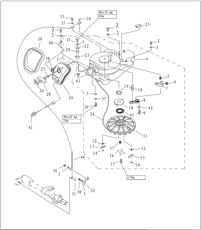
| PART NO. | DESCRIPTION | DESCRIPTION | REMARKS | ||
|---|---|---|---|---|---|
| 1 | F25-05160000 | STARTER ASSY | 1 | ||
| 2 | GB/T5783-M6x25 | M6x25 | BOLT M6x25 | 4 | |
| 3 | ;GB/T97.1-6 | 6 | WASHER,PLATE 6 | 9 | |
| 4 | F25-05160100 | CASE,STARTER | 1 | ||
| 5 | F25-05160003 | SPRING,ARRESTER | 1 | ||
| 6 | F25-05160005 | SPRING,TENSION | 1 | ||
| 7 | F25-05160001 | ARRESTER | 1 | ||
| 8 | F25-05160006 | ARRESTER,CHANGELESS | 1 | ||
| 9 | GB/T5285-ST4.8x26 | SCREW,TAPPING ST4.8x26 | 3 | ||
| 10 | F25-05160004 | PAWL,ARRESTER | 1 | ||
| 11 | F25-05160301 | WHEEL,START-UP | 1 | ||
| 12 | F25-05160304 | PAWL,DRIVE SPRING | 2 | ||
| 13 | F25-05160305 | PAWL,DRIVE | 2 | ||
| 14 | GB/T896-6 | 6 | CIRCLIP 6 | 2 | |
| 15 | F25-05160018 | PLATE,DRIVE BOLT | 1 |
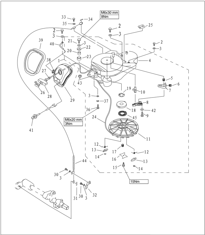
| PART NO. | DESCRIPTION | REMARKS | ||
|---|---|---|---|---|
| 16 | F25-05160017 | PLATE,DRIVE | ||
| 17 | F25-05160016 | SPRING,DRIVE PLATE | ||
| 18 | F25-05160014 | SEATSPRING | ||
| 19 | F25-05160013 | CUSHIONSPRINGSEAT | ||
| 20 | F25-05160009 | AXESPUIIEY | ||
| 21 | GB/T5783-M6x30 | M6x30 | BOLT M6x30 | |
| 22 | GB/T5287-6 | 6 | WASHEROUTSIZE 6 | |
| 23 | F25-05160008 | PUIIEY,STARTLING | ||
| 24 | F25-05160019 | φ5x1.68 | START LING | |
| 25 | F25-05160012 | JACKETRUBBER | ||
| 26 | F4-04130102 | COVER | ||
| 27 | F25-05160021 | DAMPING | ||
| 28 | F25-05160501 | HANDLE,STARTER | ||
| 29 | F25-05160401 | FRAME,STARTER | ||
| 30 | GB/T5783-M6x10 | M6x10 | BOLT M6x10 | |
| 31 | F15-00000012 | φ1.8 | SPRING | |
| 32 | F25-05000028 | STAY,CABLE COMP | ||
| 33 | GB/T5783-M5x12 | M5x12 | BOLT M5x12 | |
| 34 | F25-05160002 | φ1 | SPRING | |
| 35 | GB/T96-5 | 5 | BIG WASHER 5 |
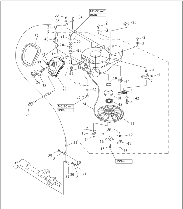
| PART NO. | DESCRIPTION | REMARKS | ||
|---|---|---|---|---|
| 36 | GB/T5783-M6x20 M6x20 | BOLT M6x20 | 2 | |
| 37 | GB/T93-6 6 | WASHER SPRING 6 | 2 | |
| 38 | HT 2.5x60 60x2.5 | CLAMP 2.5x60 | 1 | |
| 39 | F25-05160402 | SEAL,FROTHY RUBBER | 1 | |
| 40 | F25-05160403 | NOG,UNCORK | 1 | |
| 41 | F15-07130303 | SUMP INDICATOR LIGHT | 1 | |
| 42 | A5 GB/T848-5 | SMALL WASHER 5 | 3 | |
| 43 | GB/T889.1-M6 M6 | LOCK NUT | 2 | |
| 44 | F25-05160200 | CABLE COMP,STARTER STOP | 1 | |
| 45 | F25-05160015 | SPRING,VOLUTE | 1 |
Disassembling
- Open the top cowling.
- Remove the tightwire from the arrester.
Adjusting nut
- Remove the starter fixing bolts, and remove the starter.
Starter Rope Replacement
- Pull the starter rope out, and insert it in the notch of the start-up wheel. Turn the start-up wheel clockwise until the volute spring is free.
- Pull the starter rope out completely.
- Remove the starter handle cover from the starter handle, and remove the starter rope. Untie the knot at the end of the starter rope.
- Pull out the starter rope from the start-up wheel completely .
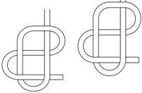
- Insert the new starter rope into the starter , and fix the starter rope onto the start-up wheel and starter handle. At the end of the rope tie a knot as shown.
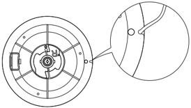
- Insert the start rope in the notch of the start-up wheel and turn the start-up wheel several rounds in counter clockwise direction.
- Pull the starter handle many times to check if the start-up wheel rotates stably and if the starter rope is slack. If necessary, repeat step 6 and step 7.
Disassembling and Inspection
- Remove the start rope and start frame assy.
- Remove arrester changeless plate. Remove arrester and arrester pawl.
- Remove drive plate screw. Remove the drive plate and drive plate spring and drive pawl.
- Remove the start-up wheel, and remove the volute spring seat and volute spring seat cushion.
WARNING: Uninstall the start-up wheel carefully, to ensure that the volute spring does not pop out to hurt people .
- Remove the volute spring.
- Inspect if the arrester and arrester pawl is cracked, worn or damaged. Replace if necessary.
- Inspect if the drive pawl is cracked, worn or damaged. Replace if necessary.
- Inspect if the pawl spring is cracked, cranked or damaged. Replace if necessary.
- Check if the volute spring and volute spring seat are broken, cranked or damaged. Replace if necessary.
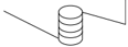
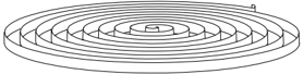
Assembling
Reverse the steps of disassembling starter.
Installation
- Put starter onto the power unit.
- Screw the hexagon bolt, and tighten it according to the specified torque.
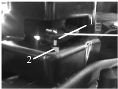
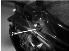
- Install the arrester tightwire.
- Adjust the changeless plate on the arrester tightwire, and align the marking of assester pawl with the marking of the starter case.
- ' ▋ 'marking 2. ' ▼ 'marking 3. arrester tightwire changeless plate
Ignition System
NOTICE:
When checking and repairing the ignition system, keep your hand, clothes, hair or personal belongings away from the rotating flywheel .
.
Check ignition coil on insulated working table, to prevent electric leak and electroshock
Don't touch the ignition coil or spark plug when the engine is running, to avoid electroshock. Keep the wires away from the rotating flywheel, to prevent the wire from being cut, or the insulating layer of the wire from being worn .
When replacing fixing parts such as nuts and bolts, only parts from original manufacturer or parts made of same material and with strength can be used. Parts must be tightened according to the specified torques .
Explosive Drawing
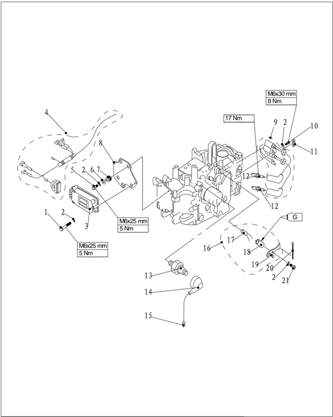
| PART NO. | DESCRIPTION | REMARKS | ||
|---|---|---|---|---|
| 1 | GB/T6563-M6x45 | SCREW ,LOCKED M6x45 M6x45 | 3 | |
| 2 | GB/T97.1-6 | WASHER 6 6 | 8 | |
| 3 | F25-05090001 | C.D.I. UNIT ASSY | 1 | |
| 4 | F25-05090002 | C.D.I. LINE ASSY | 1 | |
| 5 | GB/T5783-M6x25 | BOLT M6x45 M6x25 | 3 | |
| 6 | F25-05090005 | BUSH ,IGNITION | 3 | |
| 7 | F25-05090004 | BUSH ,DAMPING | 3 |
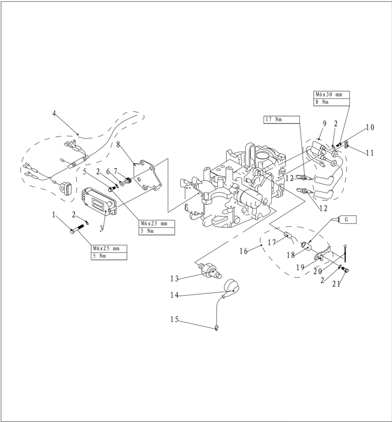
| PART NO. | DESCRIPTION | DESCRIPTION | REMARKS | ||
|---|---|---|---|---|---|
| 11 | F25-05000016 | CLAMP ,NYLON | 1 | ||
| 12 | DPR7EA 9 NGK | SPARKPLUG | 2 | ||
| 13 | F15-07010103 | OIL PRESSURE SENSOR | 1 | ||
| 14 | F15-07010101 | JACKET ,INSJULATION | 1 | ||
| 15 | F15-07010102 | LEAD WIRE ASSY | 1 | ||
| 16 | F25-05010200 | TEMPERATURE CONTROLLER ASSY | 1 | ||
| 17 | F25-05010201 | TEMPERATURE CONTROLLER | 1 | ||
| 18 | F25-05010202 | BUSH,TEMPERATURE CONTROLLER | 1 | ||
| 19 | F25-05010203 | PLATE,TEMPERATURE CONTROLLER | 1 | ||
| 20 | HT-25x60 | BAND NYLON 25x60 | 1 | ||
| 21 | GB/T5783-M6x12 | M6x12 | BOLT M6x12 | 1 |
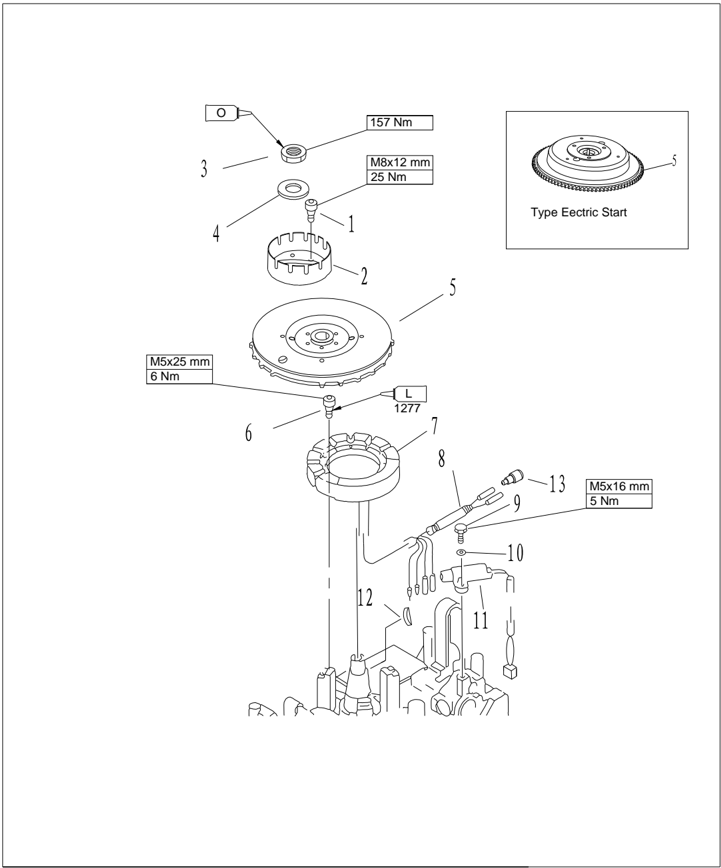
| PART NO. | DESCRIPTION | DESCRIPTION | REMARKS | |
|---|---|---|---|---|
| 1 | GB/T70.1-M8x12 | M8x12 | BOLT M8x12 | |
| 2 | F25-05000027 | JUMP STARTAXES | ||
| 3 | F25-05000026 | NUTFLYWHEEL | ||
| 4 | F25-05000025 | |||
| 5 | F25-05150000 | FLYWHEEL ASSY | ||
| F25-05150000W | FLYWHEEL ASSY | Type Eectric Start | ||
| 6 | GB/T70.1-M5x25 | M5x25 | BOLT M5x25 | |
| 7 | F25-05140000 | STATOR ASSY | ||
| 8 | F25-05000034 | Φ8x90 | RIPPLE JACKET | |
| 9 | GB/T5783-M5x16 | M5x16 | BOLT M5x16 | |
| 10 | GB/T97.1-5 | 5 | WASHER,PLATE 5 | |
| 11 | F25-05110000 | COILPULSER | ||
| 12 | F25-05000024 | |||
| 13 | F25-05110001 | INSULATED PLUG |
Electric Start
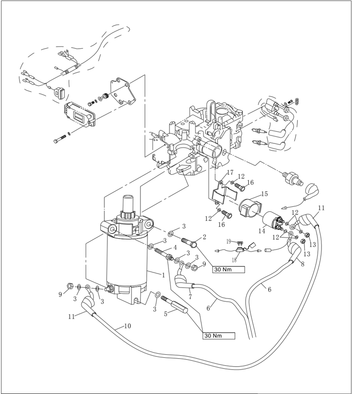
| PART NO. | DESCRIPTION | REMARKS | ||
|---|---|---|---|---|
| F25-05170100W | STARTUP MOTOR | 1 | ||
| M8×50 | 1 | |||
| GB/T97.1-85 | 8 | WASHER 8 | 7 | |
| F25-05170001W | M8 | 1 | ||
| F15-07150002W | M8 | 1 | ||
| F15-07150200W | 1 | |||
| F25-05170201W | A | 1 | ||
| F25-05170202W | B | 1 | ||
| GB/T6170-M8 | M8 | 2 | ||
| F25-05170400W | 1 | |||
| F25-05170401W | 2 | |||
| GB/T97.1-6 | 6 | WASHER 6 | 6 | |
| GB/T6170-M6 | M6 | 2 | ||
| F15-07150300W | RELAY | 1 | ||
| F25-07150301W | RELAY JACKET | 1 | ||
| M6×12 | 2 | |||
| F25-07150302W | PLANK RELAY | 1 | ||
| F25-05090100W | FUSE ASSY | 1 | ||
| F15-07150001W | 20A | FUSE | 1 |
- 1 CDI
Wiring Diagram
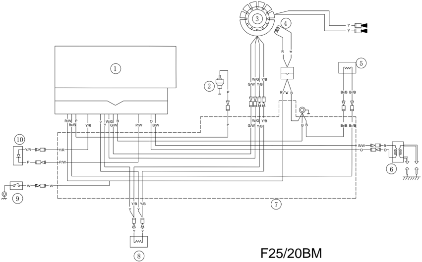
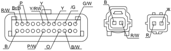
- 4 Pulsed coil
○
- 3 Stator coil
- 2 Oil pressure sensor
- 7 CDI line assy
- 6 Ignition coil
Wire beam color:
| W | White | P | Pink | W/B | White/Black |
|---|---|---|---|---|---|
| B | Black | G/W | Green/White | P/W | Pink/White |
| R | Red | Y/B | Yellow/Black | Br/B | Brown/Black |
| Y | Yellow | Y/R | Yellow/Red | W/G | White/Green |
| O | Orange | R/W | Red/White |
- 10 Oil pressure alarm lightt
- 9 Engine stop switch
- 5 Thermostat
- 8 Initial enrichment valve
Electric Start
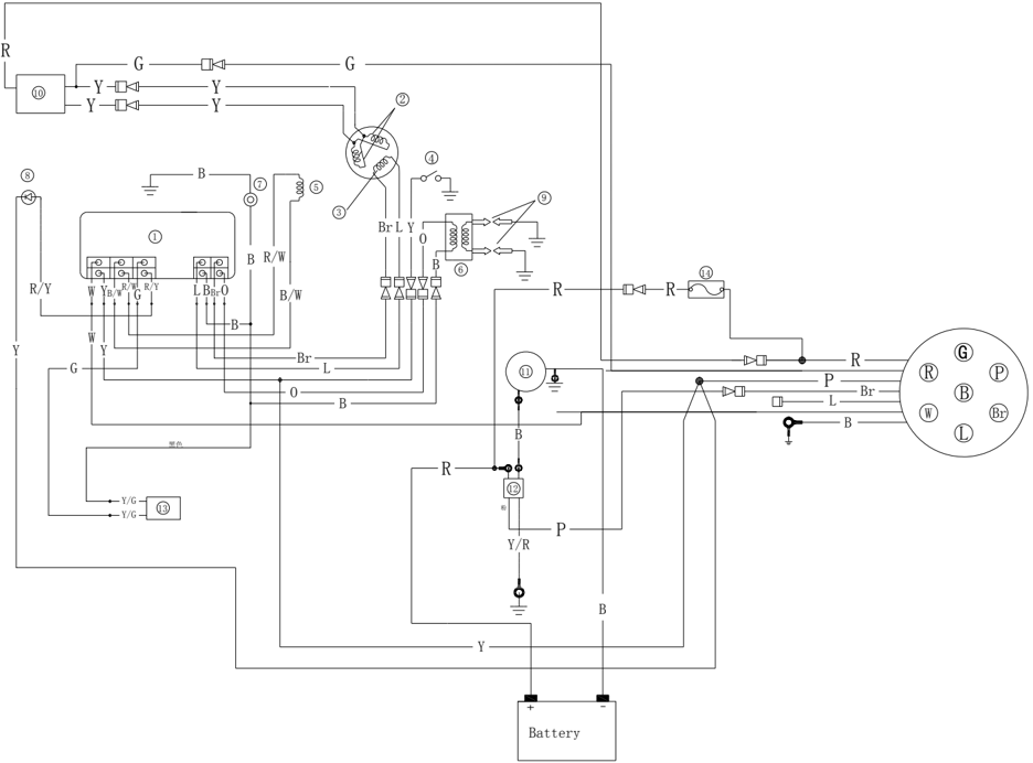
F25/20FW
- 4 Oil pressure sensor
- 5 Pulsed coil
- 6 Ignition coil
- 1 C D I
- 2 Charge coil
- 3 Lighting coil
Wire beam color:
| W | White | L | Blue |
|---|---|---|---|
| B | Black | G | Green |
| R | Red | Br | Brown |
| Y | Yellow | Y/R | Yellow/Red |
| O | Orange | R/W | Red/White |
Spark Plug Ignition
- Remove spark plug cap from spark plug.
- 7 Engine stop switch
- 8 Oil pressure alarm light
- 9 Spark plug
- 10 Rectifier assy
- 11 Startup motor
- 12 Startup relay
- 13 Initial enrichment valve
- 14 Fuse
- Connect the ignition tester to the spark plug cap.
- Start the engine, and observe the sparks through the discharge window of the tester.
WARNING:
Do not touch any joint part of the lead wire of the tester. Keep away from inflammable gas or liquid, to prevent accident resulting from spark ignition.
Spark Plug Cap
- Remove the spark plug cap. Check if the spark plug cap is broken. Replace if necessary.
- Install the spark plug cap. Turn it clockwise until it is tight.
Flywheel Maintenance
- Use flywheel gripper to remove the nut and starter bush; use flywheel puller to remove flywheel.
- Check if the flywheel is damaged or the permanent magnet part is firm. Replace if necessary.
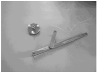
CDI Inspection
CDI Peak Voltage
Use the digital circuit tester and peak voltage adaptor to measure CDI peak voltage.
If below the specification, check the lead wire and measure the impulse and peak voltageoutput of the charge coil.
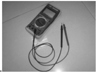
.
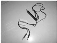
Digital circuit tester Peak voltage adaptor
| CDI peak voltage output | Start (load) | 264V |
|---|---|---|
| CDI peak voltage output | 1500 r/min | 265V |
| CDI peak voltage output | 3500 r/min | 270V |
NOTE:
If the impulse and peak voltage output of the charge coil are just same as or above the specification, and the CDI peak voltage output is below the specification, replace the CDI.
- Pulsed coil peak voltage
Use the digital circuit tester and peak voltage adaptor to measure the peak voltage. If below the specification, check the pulsed coil resistance.
Digital circuit tester Peak voltage adaptor
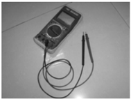
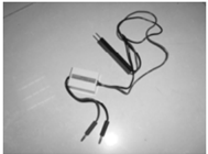
Pulsed coil peak voltage
- Pulsed coil resistance
Measure the pulsed coil resistance. Replace if out of specification, replace.
Resistance:
300~350Ω (
Tester (+) pole: red/white wire; Tester (-) pole: black wire)
Remark:
The data just for reference.
- Charge coil peak voltage
Use the digital circuit tester and peak voltage adaptor to measure the peak voltage. If below the specification, check the charge coil resistance .
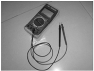
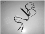
Digital circuit tester Peak voltage adaptor
| Start (no-load) | 12V |
|---|---|
| Start (load) | 12V |
| 1500 r/min (load) | 12V |
| 3500 r/min (load) | 12.4V |
Ignition Coil Inspection
- Remove the ignition coil and spark plug cap.
- Measure ignition coil resistance. Replace if out of the specification.
Resistance: 0.08
~ 0.11 Ω ( Tester (+) pole: orange wire; Tester (-) pole: black wire)
3.4 ~ 4.7k Ω
( Tester (+) pole: orange wire; Tester (-) pole: high-voltage wire)
Pulsed Coil Inspection
Charge Coil Inspection
| Chargecoil peak voltage | Start (no-load) | 294V |
|---|---|---|
| Chargecoil peak voltage | Start (load) | 291V |
| Chargecoil peak voltage | 1500 r/min (load) | 291V |
| Chargecoil peak voltage | 3500 r/min (load) | 294V |
2. Charge Coil Resistance
Measure charge coil resistance. Replace if out of specification.
Resistance: 660~710Ω ( Tester (+) pole: brown wire; Tester (-) pole: blue wire)
Fuel System (Detailed)
NOTICE:
Gasoline is inflammable and highly volatile liquid. Its leakage can cause fire and explosion. Don't start the engine before all joints of the fuel system are connected or installed. When completing all maintenance steps, force short-time pressure to the fuel system to check for leakage.
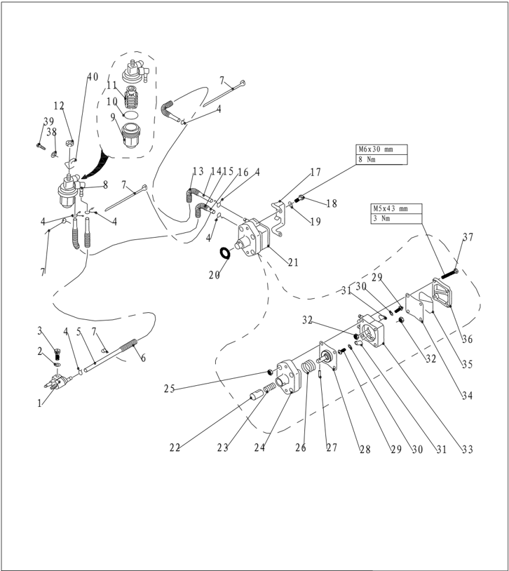
Explosive Drawing
| PART NO. | DESCRIPTION | DESCRIPTION | REMARKS | ||
|---|---|---|---|---|---|
| 1 | F4-05000200 | FUEL PIPE TIE-IN ASSY | 1 | ||
| 2 | GB/T97.1-6 | 6 | WASHER 6 | 1 | |
| 3 | GB/T5783-M6x25 | M6×25 | BOLT M6×25 | 1 | |
| 4 | F4-04000030 | B | 5 | ||
| 5 | F25-03000012 | A | PIPE ,FUEL "A" | 1 | Φ10xΦ5x550 |
| 6 | F25-03000004 | PIPE, WAVE | 1 | Φ12x120 | |
| 7 | HT-2.5×60 | 2.5×60 | CLAMP 2.5×60 | 6 | |
| 8 | F15-07080000 | FILTER ASSY | 1 | ||
| 9 | F15-07080002 | CUP ,FILTER | 1 | ||
| 10 | 1 | ||||
| 11 | F15-07080001 | ELEMENT, FILTER | 1 | ||
| 12 | GB/T6170-M8 | M8 | NUT M8 | 1 |
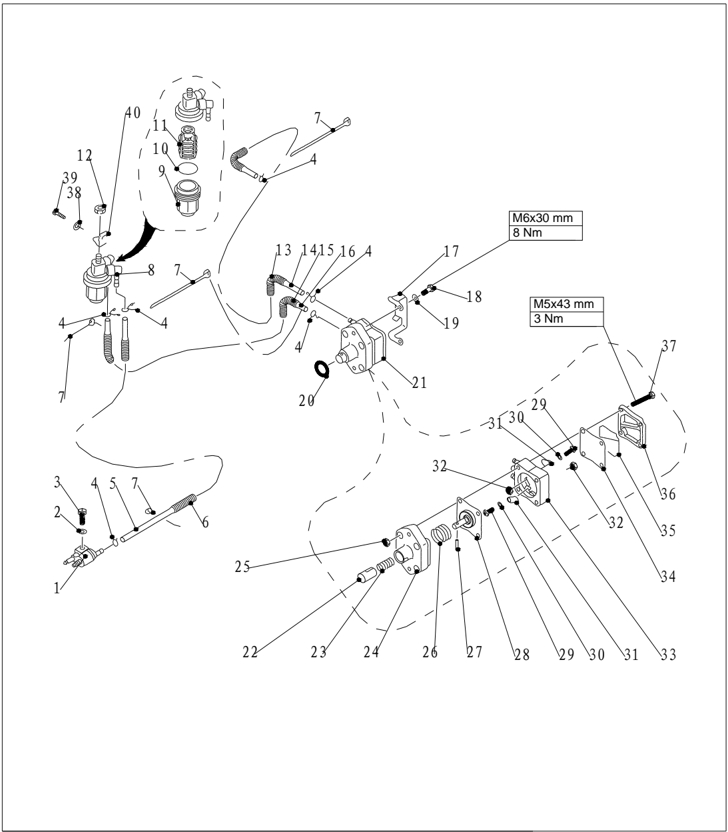
| PART NO. | DESCRIPTION | DESCRIPTION | REMARKS | ||
|---|---|---|---|---|---|
| 13 | F25-05000029 | PIPE, WAVE | 1 | Φ12x300 | |
| 14 | F25-05000012 | PIPE, FUEL | 1 | Φ10xΦ5x350 | |
| 15 | F25-05000033 | PIPE, WAVE | 1 | Φ12x120 | |
| 16 | F25-05000032 | () | HOSE | 1 | |
| 17 | F25-05000018 | 1 | |||
| 18 | GB/T5783-M6x30 | M6x30 | BOLT M6x30 | 2 | |
| 19 | GB/T97.1-6 | 6 | WASHER 6 | 2 | |
| 20 | O-RING 24.7 x3.1 | 1 | |||
| 21 | F25-05130000 | FUEL PUMP ASSY | 1 | ||
| 22 | F25-05130004 | PLUNGER | 1 | ||
| 23 | F25-05130003 | SPRING ,PLUNGER | 1 | ||
| 24 | F25-05130001 | SEAT,FUEL PUMP | 1 | ||
| 25 | GB/T6170- M5 | M5 | NUT M5 | 4 | |
| 26 | F25-05130002 | 1 | |||
| 27 | GB/T309-3x16.5 | Φ3x16.5 | 1 | ||
| 28 | F25-05130100 | DIAP HRAGM ASSY | 1 | ||
| 29 | F4-04090011 | M3x5 | 2 |
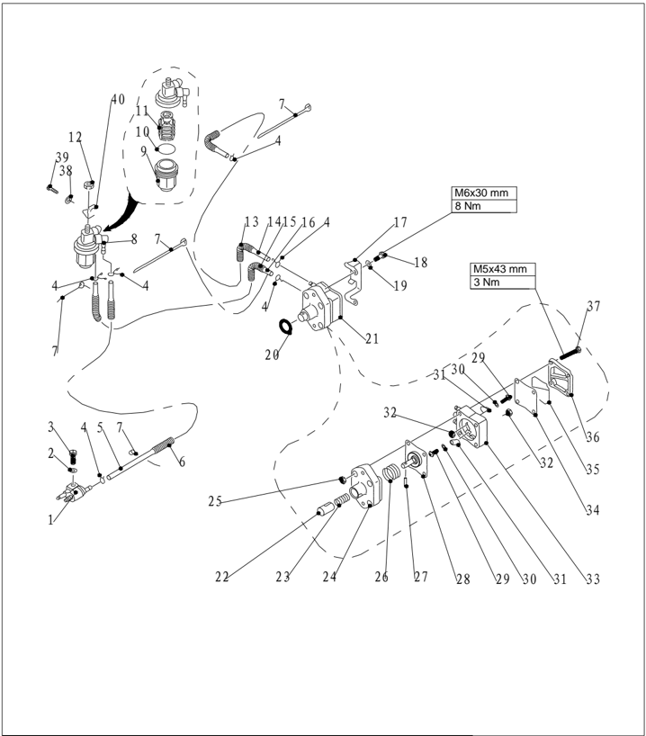
| PART NO. | DESCRIPTION | REMARKS | |||
|---|---|---|---|---|---|
| 30 | GB/T848-3 | 3 | SMALL WASHER 3 | 2 | |
| 31 | F4-04090005 | PLATE | 2 | ||
| 32 | GB/T6170-M3 | M3 | NUT 3 | 2 | |
| 33 | F25-05130201 | FUEL PUMP SHELL | 1 | ||
| 34 | F25-05130005 | DIAPHRAGMTOP | 1 | ||
| 35 | F25-05130006 | SEAL ,FUEL PUMP | 1 | ||
| 36 | F25-05130007 | COVER, FUEL PUMP | 1 | ||
| 37 | GB/T818-M5x45 | 4 | |||
| 38 | GB/T97.1-8 | 8 | WASHER 8 | 1 | |
| 39 | GB/T5783-M8x14 | M8×14 | BOLT M8×14 | 1 | |
| 40 | F25-05000017 | 1 |
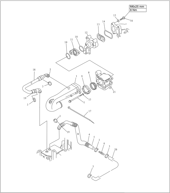
| PART NO. | DESCRIPTION | DESCRIPTION | REMARKS | ||
|---|---|---|---|---|---|
| 1 | F25-05080100 | 1 | |||
| 2 | F25-05080009 | B | BREATHER ASSY | 1 | |
| 3 | HT-3.6x150 | CLAMP | 6 | ||
| 4 | F25-05000031 | φ20x250 | HOSE | 1 | |
| 5 | F25-05080006 | B | HOSE | 1 | |
| 6 | F25-02000018 | A | PIPEJOINT | 1 | |
| 7 | GB/T5782-M6x100 | M6X100 | 2 | ||
| 8 | F25-05080004 | RUBBERSEAL | 1 | ||
| 9 | F25-05080005 | FLANGE | 1 | ||
| 10 | F25-05000011 | 0 | O-RING | 2 | |
| 11 | F25-05000009 | INSULATOR | 1 | ||
| 12 | F25-05060001 | MANIFOLD | 1 | ||
| 13 | F25-05060002 | INSERT | 1 | ||
| 14 | F25-05060003 | GASKETMANIFOLD | 1 | ||
| 15 | GB/T97.1-6 | 6 | WASHER 6 | 5 | |
| 16 | GB/T5783-M6x25 | M6X25 | 3 | ||
| 17 | HT-3.6x250 | 3.6x250 | CLAMP 3.6x250 | 1 | |
| 18 | F25-05080008 | C | HOSE | 1 | |
| 19 | F25-05080007 | A | BREATHER ASSY | 2 | |
| 20 | F25-02000017 | A | HOSE | 1 | |
| 21 | F25-05070000 | CARBURETOR ASSY | 1 |
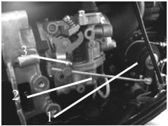
Throttle Connecting Rod Adjustment
- Turn throttle accelerograph enforce to full opening position.Turn carburetor throttle rod to full opening position
- Throttle accelerograh enforce
- Carburetor throttle rod
- Lock screw
- In full opening position, tighten the throttle rod lock screw
Fuel Joint Removal and Inspection
- Remove the bolts fixing the fuel joint.
- Remove the fuel joint.
- Inspect the fuel joint for crack or damage.
- Connect the fuel joint exit with a vacuum pressure gauge.
- Check whether the negative pressure can be maintained for over 10 minutes under the prescribed pressure. Replace if necessary.

Prescribed pressure: 50kPa
Fuel Pump Removal and Inspection
- Remove the bolts fixing the fuel pump.
- Remove the fuel pump.
- Connect the fuel pump intake with a vacuum pressure gauge.
- Block the exit of fuel pump with finger, and force a prescribed positive pressure to check for leakage.
a
Prescribed pressure: 50kP
- Force a prescribed negative pressure and check for leakage. Prescribed pressure: 50kPa
- Connect the fuel pump exit with a vacuum pressure gauge.
- Force a prescribed negative pressure and check for leakage. Disassemble the fuel pump to check if necessary. Prescribed pressure: 50kP a
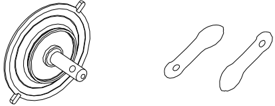
- Remove four bolts, and separate fuel pump cover from fuel pump seat.
- Remove the valve screw from fuel pump, and remove the valve plate.
- Press the plunger and diaphragm, rotate the fuel pump seat, and align the notch with the notch on the plunger. Take the roller needle out.
- Inspect the diaphragm for crack and valve for damage. Replace if necessary.
- Reverse above step 8 to step 10 to install the fuel pump.
Filter Inspection
Check if the filter element is clogged or with foreign matter. Check the filter cup for damage or leakage. Use gasoline to clean it, or replace if necessary.
NOTE:
Coat a layer of gasoline onto the O-ring before installing the filter cup.


1. Filter cup 2. O -ring 3. Filter element 4. Filter cap
Power Unit (Detailed)
NOTICE:
To avoid accidental start of outboard engine during maintenance, please take enough safety measures to disconnect the ignition system. For instance, remove the engine stop lanyard from engine stop switch assembly, and remove spark plug cap from spark plug.
Explosive Drawing
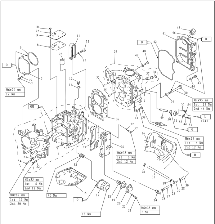
| PART NO. | DESCRIPTION | DESCRIPTION | REMARKS | ||
|---|---|---|---|---|---|
| 1 | F25-05010000 | CRANKCASE ASSY | 1 | ||
| 2 | F25-00000014 | φ8x12 | PIN,DOWEL | 2 | |
| 3 | GB/T5782-M6x35 | M6X35 | BOLT,HEXAGON M6x35 | 6 | |
| 4 | GB/T5782-M8x80 | M8X80 | BOLT,HEXAGON M8x80 | 6 | |
| 5 | F25-05000007 | BALANCE CYLINDER COVER | 1 | ||
| 6 | F25-05000010 | 0 97.5x1.9 | SEAL 97.5x1.9 | 1 | |
| 7 | GB/T5783-M6x20 | M6X20 | BOLT,HEXAGON M6x20 | 4 | |
| 8 | F25-05010108 | GASKET,BREATHER COVER | 1 | ||
| 9 | F25-05010109 | COVER,BREATHER | 1 | ||
| 10 | GB/T5783-M6x20 | M6X20 | BOLT,HEXAGON M6x20 | 4 | |
| 11 | F25-05010106 | HANGER,ENGINE | 1 | ||
| 12 | GB/T5782-M8x35 | M8X35 | BOLT HEXAGON M8x35 | 1 | |
| 13 | F15-04000002 | BOLT,OIL DRAIN | 1 | ||
| 14 | F15-04000003 | WASHER | 1 | ||
| 15 | F25-00000013 | GASKET,ENGINE | 1 | ||
| 16 | F4-04000030 | B | SPRING,FUEL PIPE"B" | 1 | |
| 17 | F15-07010023 | OIL CLEANER | 1 | ||
| 18 | F4-04000036 | THERMOSTAT | 1 |
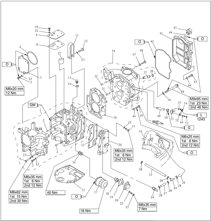
| PART NO. | DESCRIPTION | |||
|---|---|---|---|---|
| 19 | F15-07010022 | F15-07010022 | GASKET,THERMOSTAT | 1 |
| 20 | F15-07010021 | F15-07010021 | COVER,THERMOSTAT | 1 |
| 21 | GB/T5783-M6x25 M6X25 | GB/T5783-M6x25 M6X25 | BOLT M6x25 | 2 |
| 22 | 6 GB/T97.1-6 | 6 GB/T97.1-6 | WASHER 6 | 17 |
| 23 | GB/T97.1-8 8 | GB/T97.1-8 8 | WASHER 8 | 7 |
| 24 | F25-05010113 | F25-05010113 | NIPPLE,HOSE | 1 |
| 25 | F25-05010107 | F25-05010107 | CLEANER | 1 |
| 26 | F25-05010112 | F25-05010112 | 1 | |
| 27 | F25-03000008 A | F25-03000008 A | HOSE | 1 |
| 28 | HT-2.5x60 | HT-2.5x60 | CLAMP | 5 |
| 29 | F15-05000011 | F15-05000011 | THREE-WAY PIPE | 1 |
| 30 | C F25-03000011 | C F25-03000011 | HOSE | 1 |
| 31 | B F25-03000009 | B F25-03000009 | HOSE | 1 |
| 32 | F15-07010003 | F15-07010003 | BOLT,UNION | 1 |
| 33 | F25-05010111 | F25-05010111 | 1 | |
| 34 | F25-05050100 | F25-05050100 | 1 | |
| 35 | F25-00000014 φ8x12 | F25-00000014 φ8x12 | PIN,DOWEL | 2 |
| 36 | F25-05040000 | F25-05040000 | 1 | |
| 37 | F25-05050104 | F25-05050104 | VALVE GUIDE BUSH | 4 |
| 38 | F15-07040105 | F15-07040105 | 4 | |
| 39 | M6X25 GB/T5783-M6X25 | M6X25 GB/T5783-M6X25 | 3 | |
| 40 | F25-05000002 | F25-05000002 | BOLT,FLANGE | 6 |
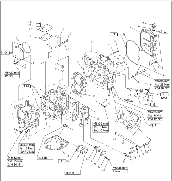
| PART NO. | DESCRIPTION | DESCRIPTION | REMARKS | ||
|---|---|---|---|---|---|
| 41 | F25-05000005 | 1 | |||
| 42 | F25-05000004 | 1 | |||
| 43 | GB/T5783-M6X20M6X20 | 5 | |||
| 44 | GB/T97.1-6 | 6 | WASHER,PLATE 6 | 10 | |
| 45 | F15-07050004 | PLUG,OIL | 1 | ||
| 46 | O-RING 31-025 | 1 | |||
| 47 | F25-05050007 | GASKET | 1 | ||
| 48 | F25-05050006 | BOLT | 1 | ||
| 49 | F25-02010005 | ANODE | 2 | ||
| 50 | F15-07010009 | GROMMET,ANODE | 2 | ||
| 51 | F15-07010011 | COVER,ANODE | 2 | ||
| 52 | F15-07010012 | PLATE,ANODE | 2 | ||
| 53 | GB/T5783-M6X20 | M6X20 | 2 | ||
| 54 | GB/T5783-M5X12 | M5X12 | 2 | ||
| 55 | GB/T97.1-5 | 5 | WASHER,PLATE 5 | 2 | |
| 56 | F25-050000039 | WASHER,PLATE 9 | 6 | ||
| 57 | GB/T5783-M6X35 | M6X35 | BOLT M6X35 | 7 |
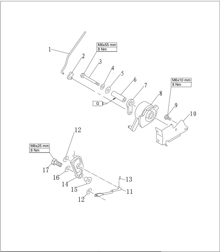
| PART NO. | DESCRIPTION | DESCRIPTION | REMARKS | ||
|---|---|---|---|---|---|
| 1 | F25-05000008 | ||||
| 2 | F15-07000016 | ||||
| 3 | GB/T5782-M6x55 | M6x55 | BOLT M6x55 | ||
| 4 | GB/T97.1-6 | 6 | WASHER 6 | ||
| 5 | GB/T96-6 | 6 | LARGE WASHER 6 | ||
| 6 | F15-07000012 | ||||
| 7 | F15-07000014 | PULLEY ,PASSIVITY | |||
| 8 | F15-07000013 | PULLEY ,DRIVE | |||
| 9 | GB/T5783-M6x10 | M6x10 | BOLT M6x10 | ||
| 10 | F15-07000011 | ||||
| 11 | F25-03030004W | B | LINK ROD ,SHIFT | 1 | Type Electric Start |
| 12 | GB/T96-5 | 5 | BIG WASHER 5 | 2 | Type Electric Start |
| 13 | F25-05160002 | φ1 | SPRING | 1 | Type Electric Start |
| 14 | F25-03000027W | PLATE ,SHIFT | 1 | Type Electric Start | |
| 15 | F25-03000028W | BUSH ,LIMITED PLATE | 1 | Type Electric Start | |
| 16 | GB/T5287-6 | 6 | SUPPER WASHER 6 | 1 | Type Electric Start |
| 17 | GB/T5783-M6x25 | M6×25 | BOLT M6X25 | 1 | Type Electric Start |
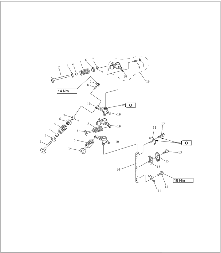
| PART NO. | DESCRIPTION | DESCRIPTION | REMARKS | ||
|---|---|---|---|---|---|
| F25-05050001 | VALVE,INTAKE | 2 | |||
| F25-05050002 | VALVE,EXHAUST | 2 | |||
| F25-05050003 | 4 | ||||
| PS-2700.04.03 | SEAL,VALVE STEM | 4 | |||
| F25-05050005 | SPRING,VALVE | 4 | |||
| F15-07040006 | 4 | ||||
| F15-07040007 | COTTER,VALVE | 8 | |||
| F15-07040303 | 1x4 | ||||
| F15-07040304 | NUT | 1x4 | |||
| F25-05050301 | ROCKER | 1x4 | |||
| 11 | F25-05050009 | A | 2 | ||
| 12 | F25-05050011 | SPRING | 1 | ||
| 13 | F25-05050019 | BOLT | 3 | ||
| 14 | F25-05050008 | SHAFT,ROCKER | 1 | ||
| 15 | F25-05050012 | B | 1 | ||
| 16 | F25-05050300 | ROCKER ASSY | 4 |

| PART NO. | DESCRIPTION | DESCRIPTION | REMARKS | ||
|---|---|---|---|---|---|
| 1 | F25-05020001 | CRANK SHAFT | 1 | ||
| 2 | F25-05020002 | B | OIL SEAL B | 1 | |
| 3 | F25-05010302-1 | MAIN BEARING | 6 | ||
| F25-05010302-2 | MAIN BEARING | 6 | UR:BROWN | ||
| 4 | F25-05020204 | 2 | |||
| 5 | F25-05020203-1 | 2 | UR:BLACK | ||
| F25-05020203-2 | 2 | ||||
| 6 | F25-05020101 | PISTON | 2 | ||
| 7 | F25-05020105 | PIN,PISTON | 2 | ||
| 8 | F25-05020106 | CIRCLIP | 4 | ||
| 9 | F25-05020102 | I | PISTON RING I | 2 | |
| 10 | F25-05020310 | 1 | |||
| 11 | F25-05020301 | PISTON,BALANCE | 1 | ||
| 12 | F25-05000026 | NUT | 1 | ||
| 13 | F25-05020002 | A | OIL SEAL A | 1 | |
| 14 | F25-05020103 | Ⅱ | PISTON RING Ⅱ | 2 | |
| 15 | F25-05020104 | COMBINA OIL RING | 2 | ||
| 16 | F25-05020100 | PISTON ASSY | 2 | ||
| 17 | F25-05020200 | ROD,CONNECTING | 2 |
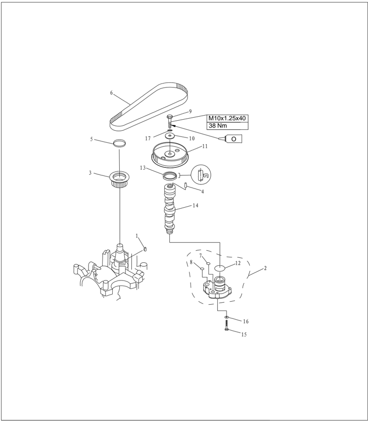
| PART NO. | DESCRIPTION | DESCRIPTION | REMARKS | |
|---|---|---|---|---|
| F4-04000019 | KEY,WOODRUFF | 1 | 4x5.3x13 | |
| F25-05050400 | OIL PUMP ASSY | 1 | ||
| F25-05000021 | 1 | |||
| F25-05050016 | PIN,DOWEL | 1 | 5x3.8 | |
| F25-05000022 | BUSH,SPRING | 1 | ||
| F25-05000023 | BELT,TIMING | 1 | ||
| F25-05050013 | 0A | 0-RING A | 1 | 11.6x1.22 |
| F25-05050014 | 0B | 0-RING B | 1 | 13.8x1.9 |
| BOLT M10x1.25x40 | 1 | |||
| F25-05050018 | WASHER,PLATE | 1 | ||
| F25-05050017 | 1 | 33.5x1.9 | ||
| F25-05050015 | 0C | 0-RING C | 1 | |
| F25-05050021 | OIL SEAL 37X50X7R | 1 | ||
| F25-05050200 | CAMSHAFT ASSY | 1 | ||
| GB/T5782-M6x35 | M6x35 | BOLT M6x35 | 4 | |
| GB/T97.1-6 | 6 | WASHER,PLATE 6 | 4 | |
| GB/T97.1-10 | 10 | WASHER,PLATE 10 | 1 |
Electric Start Type
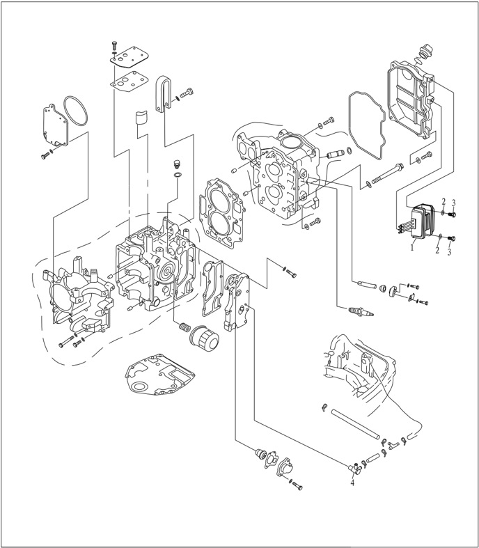
| PART NO. | DESCRIPTION | DESCRIPTION | REMARKS | |
|---|---|---|---|---|
| F25-05170500W | RECTIFIER ASSY | 1 | ||
| GB/T97.1-6 | 6 | WASHER 6 | 2 | |
| GB/T5783-M6x12 | M6X12 | BOLT,HEXAGON M6X12 | 2 | |
| F25-05010400W | NOZZLEASSY | 1 |
Special Tools
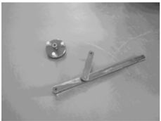
Flywheel gripper and flywheel puller
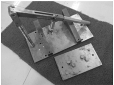
Piston slider
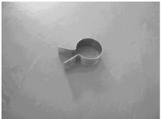
Valve spring compressor
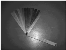
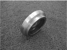
Space gauge Oil cleaner spanner
Compression Pressure Inspection
- 1. Start the engine and preheat it for 5 minutes. Then stop it.
- 2. Remove stopper hang rope.
- 3. Remove spark plug and attach pressure gauge to spark plug hole.
CAUTION:
Before removing spark plug, use compressed air to clean the spark plug notch, to prevent dust and other foreign matter from entering cylinder.
- 4. Open the choke completely, and rotate the crankshaft with starter. When the pressure gauge readings become stable, check the cylinder pressure.
NOTE:
Please don't change the choke position when checking the cylinder pressure.
For models that use control box, remove the throttle link and open completely the carburetor throttle rod by hand, and then measure the pressure.
- 5. If the measured pressure is below the specification or there is difference between cylinders, add a little oil into cylinders and measure again.
Compression pressure: 810 kPa
NOTE:
If the cylinder pressure increases continuously, check piston and piston ring for damage. Replace if necessary.
If the cylinder pressure doesn't increase at all, check valve clearance, valve, valve seat, cylinder liner, cylinder cover and cylinder cover gasket. Adjust or replace if necessary.
The outboard engine comes with an automatic decompression device, so the pressure data measured may have variance.
Oil Pressure Inspection
- Start the engine and preheat it for 5 minutes. Then stop it.
- Remove the oil pressure switch and attach the pressure gauge
NOTE:
Please use the pressure gauge equipped with 1/8in pitch thread adapter.
- Check the oil pressure. Oil pressure (reference data): 80kPa (Idling speed)
Oil Pressure Switch Inspection
- Remove the oil pressure switch and attach the vacuum pressure gauge.
- Load the stated pressure on oil pressure switch. Inspect the continuity of oil pressure switch with digital circuit tester. Replace if unqualified
| Pressure | Continuity |
|---|---|
| Above 14.7kPa | Discontinuous |
| Below 14.7kPa | Continuous |
Disassembling Power Unit
- Open the top cowling.
- Remove starter.
- Remove throttle cable.
- Remove carburetor.
- Remove flywheel with special tool.
- Remove bolts connecting power unit and upper casing.
- Lift the engine and remove the pin.
- Remove the woodruff key.
- Disconnect the engine stop switch wire and ground wire
Flywheel gripper and flywheel puller
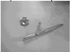
.
- Remove throttle cable (manual start models) or cable joint (electric start models).
- Remove charge coil, lighting coil and pulsed coil.
- Remove high-pressure assembly, CDI unit, ignition coil, oil pressure switch and spark plug.
Belt Pulley and Timing Belt
- Rotate the flywheel clockwise. Align the mark '1' on the driven belt pulley with the mark ' ▼ ' on the cylinder cover.
CAUTION:
Please don't rotate the flywheel counter clockwise. Otherwise, valve system will be damaged.
- Remove timing belt from side of driven belt pulley
CAUTION:
Please don't rotate the belt pulley before timing belt is fixed. Otherwise, valve system will be damaged.
- Remove driven belt pulley bolt, driven belt pulley and woodruff key.
NOTE:
Please remove driven belt pulley bolt with flywheel gripper.
Please don't rotate camshaft while unscrewing the timing belt pulley.
- Remove timing belt pulley gasket, timing belt pulley and woodruff key.
- Check belt pulley and timing belt for crack, damage and wear. Replace if necessary.
- Assemble woodruff key and driven belt pulley. ▼
Align the mark '1' on the driven belt pulley with the mark ' ' on the cylinder cover. Tighten the driven belt pulley bolt temporarily.
CAUTION:
Please don't rotate the belt pulley before timing belt is fixed. Otherwise, valve system will be damaged.
- Assemble wood ruff key and timing belt pulley: ▼
Align the notch mark on the timing belt pulley with the mark ' ' on the crankcase.
- Assemble new timing belt. Remember to put the timing belt part number vertical and upward.
CAUTION:
Please don't distort, rotate or bend the timing belt. Otherwise, it will be damaged.
Please keep timing belt from gasoline or oil.
Please don't rotate belt pulley counter clockwise. Otherwise, the valve system will be damaged.
- Rotate timing belt pulley clockwise for two loops to eliminate the slack of timing belt pulley. Check whether alignment marks are aligned well.
- Tighten bolt and nut
Locking torque: Driven belt pulley bolt 38 Nm.
NOTE:
Remove driven belt pulley bolt with flywheel gripper.
Tighten timing belt pulley nut with special timing belt pulley nut barrel spanner.
Disassembling and Inspection
Cylinder Cover
Disassembling
- Remove the bolts of cylinder head cover
- Remove the bolts of the cylinder cover according to the reverse numbering sequence marks on the cylinder cover.
- Remove the cylinder cover. Remove the oil pump.
- Remove the rocker arm shaft, spring and rocker arm assy.
NOTE:
Before removing rocker arm shaft, unscrew lock nut and adjust screw to slack.
- Use the valve spring compressor to remove intake valve and exhaust valve.
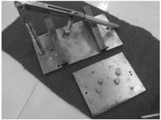
Valve and Valve Guide Bush
- Inspect the valve seat width. If not in the prescribed range, repair the valve seat. Valve seat width:
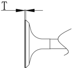
- Inspect the valve margin thickness (T). If not as in the prescribed value, replace the valve. The margin thickness of valve: T
- Inspect the valve stem diameter. If not as in the prescribed value, replace the valve. The diameter of valve stem:
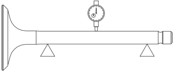
- Measure the valve stem runout. If exceeding the limit, replace the valve. Value stem runout limit: 0.03mm
- Measure the inside diameter of the valve guide bush. The inside diameter of the valve guide bush: 5.500 ~
| Valve seat width: Intake valve | 1.84 2.97mm |
|---|---|
| Exhaust valve | 1.98 3.11mm |
| Intake value | 0.8mm |
|---|---|
| Exhaust value | 0.9mm |
| Intake value | 5.475 5.490mm |
|---|---|
| Exhaust value | 5.460 5.475mm |
CAUTION:
When replacing the valve, use a new valve guide bush and valve oil seal.
Valve Spring
- Measure the free length of valve spring. If less than prescribed value, replace.
- Measure the valve spring tilt. If exceeding the prescribed limit, replace.
The minimum free length: 38.4 mm
The maximum tilt limit: 1.7 mm
Valve Rocker Arm and Rocker Shaft
5.512mm
- Check the interface between the valve rocker arm and rocker shaft for wear. Replace if necessary.
- Measure whether the inside diameter of valve rocker arm and outside diameter of rocker shaft are within prescribed value.
The inside diameter of valve rocker arm:
16.000 ~ 16.018mm
The outside diameter of rocker shaft:
15.971 ~ 15.991mm
Camshaft
| Height | 30.834~31.034mm |
|---|---|
| Base circle diameter | 25.90~26.10mm |
- Check the camshaft size.
Replace if necessary.
- Check camshaft run out. Replace if necessary.
Roundness limit: 0.03mm
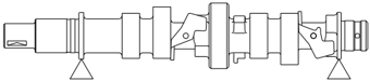
- 3 . Check main journal diameter of camshaft. Replace if necessary.
- Check the automatic decompression device for crack and damage. Replace the camshaft if necessary.
Main journal diameter (TOP):
36.925~36.945mm
Main journal diameter (CENTER):
36.935~36.955mm
Oil Pump Check
- Remove screw and oil pump.
- Check rotor clearance of oil pump. Replace if out of specification.
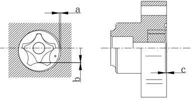
| Clearance between external rotor and casing a | 0.09~0.15mm |
|---|---|
| Clearance between external rotor and internal rotor b | 0.12mm |
| Clearance between rotor and cover c | 0.03~0.08mm |
Valve Guide Bush Replacement
- Knock out the valve guide bush from the direction of combustion room.
- Knock in the new valve guide bush from the direction of the top of cylinder cover.
NOTE:
Coat the oil on the surface of pipe before installation.
- Bore the inside diameter of pipe to the prescribed value by reamer.
Inside diameter of valve pipe: 5.500
~ 5.512mm
NOTE:
When taking out the reamer, don't rotate it in counter clockwise direction.
Valve Seat Inspection
- Clean the carbon on the valve.
- Coat a thin layer of bluing dye evenly onto the seal face of the valve seat.
- Lap the valve on the valve seat by valve lapping tool.
- Measure the valve seat width.
The valve face is with bluing dye.
If the valve and valve seat do not match, or the valve seat width does not conform to specified value, reface and grind the valve seat.
If the contact surface is not even, replace the valve guide bush.
The valve seat width: 0.9
~ 1.1mm
Valve Seat Cutting
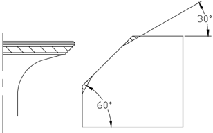
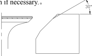
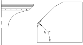
- Use 45 o valve seat cutter to adjust the valve seat width. Turn the cutter clockwise until the valve seat face is smooth.
- If the valve seat is centered on the valve face but it's too wide, to reduce the valve seat width, use 30 o cutter to adjust the top edge of the seat, and use 60 o cutter to adjust the bottom edge of the seat.
- If the valve seat is too narrow and on the top edge of valve surface, use 30 o cutter to adjust the top margin of the seat, and use 45 o cutter to adjust the valve seat width if necessary. 。
- If the valve seal surface is too narrow and on the bottom edge of valve surface, use 60 o cutter to adjust the bottom edge of the seat, and use 45 o cutter to adjust the valve seat width if necessary
- Coat evenly a thin layer of lapping compound onto valve seat, and lap the valve by lapping tool.
- Clean up the remaining lapping compound.
- Inspect again the valve seat width.
CAUTION:
Do not overlap the valve. Turn the lapping tool evenly with a downward force of 40~50N. Do not contaminate push rod and valve guide bush with lapping compound.
Valve Installation
- Install new valve oil seal and spread engine oil to the inside of the valve guide bush.
- Install valve, valve spring seal, valve spring and valve spring retainer in sequence.
- Compress the valve spring with valve spring compressor and install valve cotter.
- Knock valve spring retainer slightly with plastic or rubber hammer to fix the valve cotter.
Assembling Cylinder Cover
- Install new oil seal with special tool.
- Install camshaft into cylinder cover from the direction of oil pump.
- Check whether spline position is facing the conjunction surface of cylinder. Adjust if necessary.
- Install rocker arm assembly, spring and rocker shaft.
- Assemble oil pump.
NOTE:
Ensure mark on the external rotor is facing the oil pump cover.
- Align oil pump drive shaft with camshaft pin, then install oil pump.
CAUTION:
Before installing oil pump, make sure the oil passage is through, and fill the oil pump with oil.
Crankcase
Disassembling
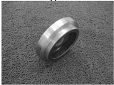
- Remove the oil cleaner with special tool. NOTE:
Put one piece of cloth under oil cleaner.
Oil cleaner spanner
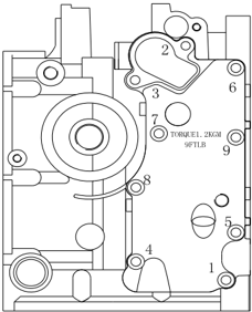
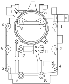
- Remove the bolts according to the sequence shown in the picture.
- Remove the thermostat cover, exhaust outer cover, gasket and pins. 。 Clean the anode surface and check the anode. Replace if the corrosion of anode is abnormal. Check the exhaust outer cover for crack, distortion or corrosion. Replace if necessary.
- Remove the balance cylinder cover, and remove nut and balance cylinder piston.
- Remove the crankcase bolts according to the sequence shown in the picture, and remove the base.
- Remove the connecting rod bolts and connecting rod cover, remove the crank, and remove connecting rod and piston assy.
- Remove piston pin circlip with plier, and remove piston pin and piston.
- Remove oil seal, pin and main bearing.
Balance Cylinder Piston and Connecting Rod
- 1 . Check the balance cylinder piston for crack or damage. Replace it if necessary.
- Check the balance cylinder connecting rod assy for crack or damage. Replace it if necessary.
Piston
- Measure piston outside diameter at the specified measuring point. If out of specification, replace.
- Check the piston pin inside diameter. If out of specification, replace
Piston diameter:
64.950 ~ 64.965 mm
Measuring point ○
a : 2 mm
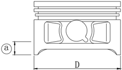
Piston pin inside diameter: 15.974
~ 15.985mm
Cylinder Bore
- Measure cylinder bore separately at measuring point ○ 1 ,○ 2 ,○ 3 . At each point, measure the cylinder bore at places D1, D3, D5 parallel to the crankshaft and at places D2, D4, D6 ertical to the crankshaft. ②
- Calculate taper limit and round limit. If out of specification, replace crankcase.
Measuring point height:
○ 1 20 mm ;
○ 2 40 mm ;
○ 3 60 mm
Cylinder bore:
65.000 ~ 65.015 mm
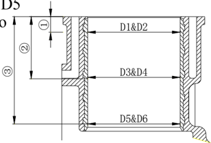
Taper limit: 0.08mm
(D1-D5, D2-D6)
Round limit: 0.05 mm
(D2-D1, D6-D5)
Piston Pin Outside Diameter
Measure piston pin outside diameter. If out of specification, replace it.
Piston pin outside diameter: 15.965
~ 15.985mm
Piston Ring
- Push the piston ring parallel with the piston into the specified measuring point of the cylinder (20mm from conjunction surface).
- Measure end gap by space gauge. If out of specification, replace the piston ring.
End gap (installed):
Top ring
2nd ring
Oil ring
0.15 ~ 0.30mm
0.30 ~ 0.50mm
0.20 ~ 0.70mm
- Install piston ring to piston, and measure side clearance between piston ring and its slot by space gauge. If out of specification, replace the piston ring.
Side clearance:
Top ring:
0.02 ~ 0.06 mm
2nd ring: 0.02
~ 0.06 mm
Oil ring: 0.04
~ 0.18 mm
Connecting Rod Small End Inner Diameter
Measure the connecting rod small end inner diameter. If out of specification, replace it. 。
Connecting rod small end inner diameter:
15.985 ~ 15.998mm
Connecting Rod Big End Side Clearance
Measure connecting rod big end side clearance. If out of specification, replace connecting rod or crankshaft, or replace both.
Connecting rod large end side clearance:
0.05 ~ 0.22 mm
Crankshaft
- Measure diameter of crankshaft main journal, crankpin diameter and crankpin width. If out of specification, replace the crankshaft.
| Diameter of crankshaft main journal | 42.984~43.000mm |
|---|---|
| Crankpin diameter | 32.984~33.000mm |
| Crankpin width | 21.000~21.070mm |
- Measure crankshaft run out. If out of specification, replace it.
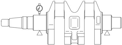
Crankshaft run out limit: 0.05mm
Crankpin Oil Clearance
- Put a piece of plastic space gauge on to the crankpin in parallel to the crankshaft.
- Assemble connecting rod and main bearing to the crankpin.
- Tighten the connecting rod bolts to the specified torque.
- Remove the connecting rod, measure the compressed width of the plastic space gauge. If out of specification, replace the main bearing.
Tightening torque:
First tightening 6 Nm
Second tightening 17 Nm
Oil clearance: 0.020
~ 0.052mm
NOTE:
Don't rotate the connecting rod before completing measurement.
Main Journal Oil Clearance
- Clean main bearing, main journal and fitting surface of crankcase and crankcase base.
- Install main bearing and crankshaft to crankcase.
- Put one plastic space gauge on the main journal, paralleling with crankshaft.
NOTE:
Don't put plastic space gauge on the oil hole of main journal.
- Install main bearing onto crankcase base and install crankcase base onto crankcase.
- Following the numbering sequence on the crankcase base, tighten the bolts at specified torques.
Tightening torques:
| First tightening | M8 | 15 Nm |
|---|---|---|
| Second tightening | M8 | 30 Nm |
| First tightening | M6 | 6 Nm |
| Second tightening | M6 | 12 Nm |
- Remove crankcase and measure the compressed width of each plastic gauge. If out of specification, replace the main bearing.
Oil clearance:
0.012 ~ 0.044mm
NOTE:
Please don't rotate the crankshaft before the measurement is completed.
Crankcase and Crankcase Base
- Inspect crankcase base and crankcase for crack, damage or wear. Replace if necessary.
- Inspect cooling water passage for dirt or clog. Clean if necessary.
Full Installation
Piston Connecting Rod Installation
Install piston, connecting rod, piston pin and piston pin circlip.
NOTE:
When installing, make sure that the mark on the connecting rod is on the same side as the mark on the piston crown.
Piston Ring Installation
- Install oil ring, 2nd ring and top ring.
NOTE:
Make sure that the mark is toward the piston crown when installing the 2nd ring.
- Picture of the piston ring gap
Oil ring end gap 1 (lower rail)
Oil ring end gap 2 (expanded ring)
Oil ring end gap 3 (upper rail)
2nd piston ring end gap 4
Top piston ring end gap 5
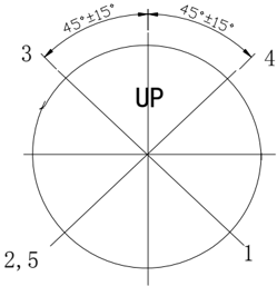
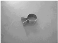
Piston Installation
Use piston slider to install piston, and make sure that the piston crown 'UP' is toward the flywheel side
NOTE:
Apply engine oil to the piston and piston ring side when installing.
Crankshaft Installation
.
- Install main bearing to crankcase
NOTE:
Insert the protruding part of main bearing into the corresponding slot of crankcase.
- Install balance cylinder connecting rod to crankshaft.
- Install the crankshaft to crankcase. Install oil seal.
NOTE:
Apply engine oil to the inner side of oil seal before installing.
- Install connecting rod cover onto the connecting rod, and tighten the connecting rod bolt to the specified torque in two steps.
Tighten torque:
First tightening
6 Nm
Second tightening 17 Nm
NOTE:
Align the marking on connecting rod cover with the marking on connecting rod.
Apply engine oil to connecting rod bolt before installing.
Assembling Power Unit
- Install the main bearing to crankcase base.
- Apply fluid sealant to conjunction surface of the crankcase base, and install dowel pin and crankcase base. Tighten the bolts twice according to the sequences on the right picture.
Tighten torque:
NOTE:
Apply engine oil to moving parts before installing
Apply engine oil to the bolt before installing.
- Install balance cylinder piston, and tighten the piston nut at specified torques Tighten torque: 157 Nm
NOTE:
Apply engine oil to the nut before installing.
- Install new O-rings and balance cylinder cover, and tighten the bolt at specified torque.
Tighten torque:
12 Nm
NOTE:
Apply engine oil to the bolt before installing.
- Install oil cleaner by special tool and tighten it at specified torques. Tighten torque: 18 Nm
NOTE:
Pour engine oil into oil channel before installing.
| First tightening | M8 | 15 Nm |
|---|---|---|
| Second tightening | M8 | 30 Nm |
| First tightening | M6 | 6 Nm |
| Second tightening | M6 | 12 Nm |
.
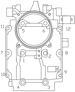
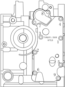
- Install exhaust outer cover, thermostat and thermostat cover. Tighten bolts twice according to sequences as shown in picture.
- Install dowel pin, cylinder gasket and cylinder cover assembly.
- Inspect the position of woodruff key slot on camshaft.
- Tighten the cylinder cover bolts twice to specified torque according to sequences on right picture. Tighten torque:
Tighten torque:
First tightening
6 Nm
Second tightening
12 Nm
| First tightening | M9 | 23 Nm |
|---|---|---|
| Second tightening | M9 | 46 Nm |
| First tightening | M6 | 6 Nm |
| Second tightening | M6 | 12 Nm |
NOTE:
Do not use the old gasket
- Install timing belt pulley, driven belt pulley, timing belt and breather pipe.
- NOTE:
When installing, make ensure that the marking on the driven belt pulley is aligned with the " ▼ " on the cylinder cover; and the marking on the timing belt pulley is aligned with the " ▼ " mark on the crankcase.
- Adjust valve clearance.
- Install cover of cylinder cover and tighten bolt according to sequences on right picture.
- Install throttle cable bracket and throttle accelerograph enforce.
- For electric start models, install gear shift limitative rod firstly.
- Install oil pressure switch, ignition coil, C.D.I. unit assy. and rectifier and regulator assy.
- Install pulsed coil, lighting coil and charge coil.
- Install fuel system.
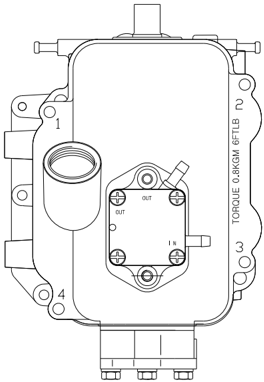
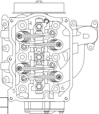
Upper Unit
Top Cowling
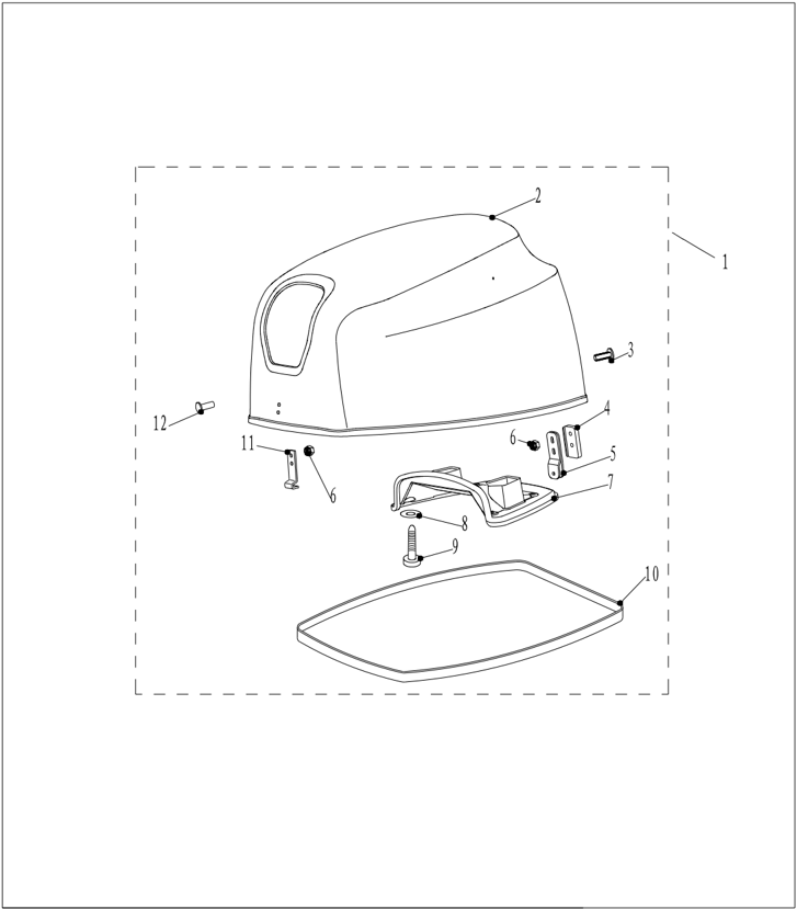
Explosive Drawing
| PART NO. | DESCRIPTION | REMARKS | |
|---|---|---|---|
| F25-06000000 | TOP COWLING ASSY | ||
| F25-06000001 | TOP COWLING | ||
| F25-06000007 | FLAT BOLT | ||
| F25-06000005 | |||
| F25-06000100 | |||
| GB/T6184-M6 | NUT M6 | ||
| F25-06000003 | |||
| F4-06000004 | WASHER,RUBBER | ||
| F25-06000002 | SEAL | ||
| F25-06000004 | POTHOOK,FRONT | ||
| F25-06000006 | B | FLAT BOLT "B" |
- Remove rubber seal.
- Remove top cowling muffle cover screw and rubber underlay.
- Remove top cowling muffle cover.
- Remove locking hook and pothook.
- Inspect top cowling for crack or damage. Replace if necessary.
- Inspect rubber seal for crack or damage. Replace if necessary.
- Inspect top cowling muffle cover for crack or damage. Replace if necessary.
- Inspect lock hook and pothook for crack, deform or damage. Replace if necessary.
Disassembling and Inspection
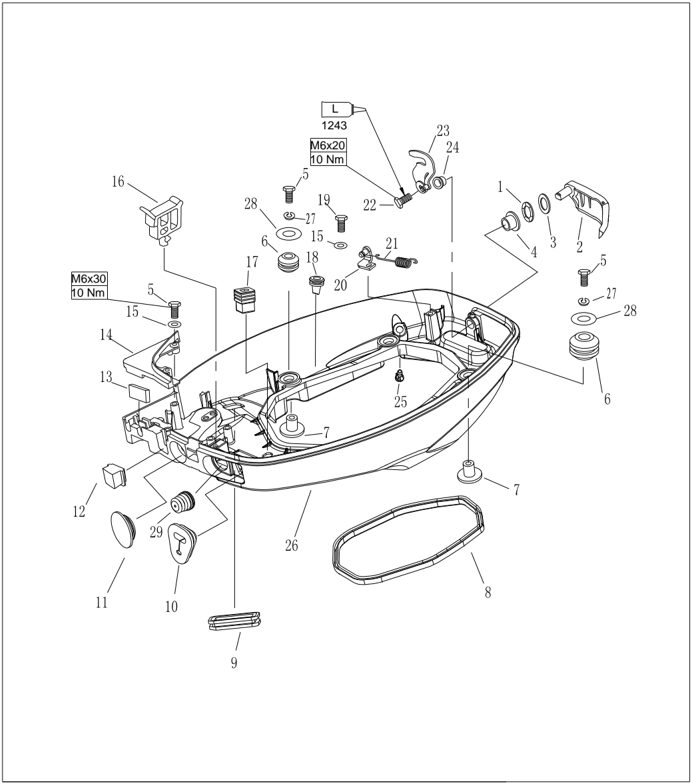
Bottom Cowling
Explosive Drawing
| PART NO. | DESCRIPTION | REMARKS | ||
|---|---|---|---|---|
| F15-05000023 | F15-05000023 | WASHER ,WAVE | 1 | |
| F25-03010000 | 1 | |||
| F25-03000015 | WASHER | 1 | ||
| F15-05000022 | BUSHING A | 1 | ||
| GB/T5783-M6x30 | M6x30 | BOLT, HEXAGON M6x30 | 6 | |
| F25-03000006 | F25-03000006 | DAMPER | 4 | |
| F25-03000007 | F25-03000007 | BUSHING,DAMPER | 4 | |
| F25-03000002 | F25-03000002 | 1 | ||
| F15-05000003 | F15-05000003 | 1 | ||
| F15-01000015 | F15-01000015 | JACKET,CABLE | 1 | |
| F25-03000003 | F25-03000003 | 1 | ||
| F25-03000013 | F25-03000013 | 1 | ||
| F15-05000017 | SEAL,RUBBER | 1 | ||
| F25-03000014 | 1 | |||
| GB/T97.1-6 | 6 | WASHER 6 | 3 |
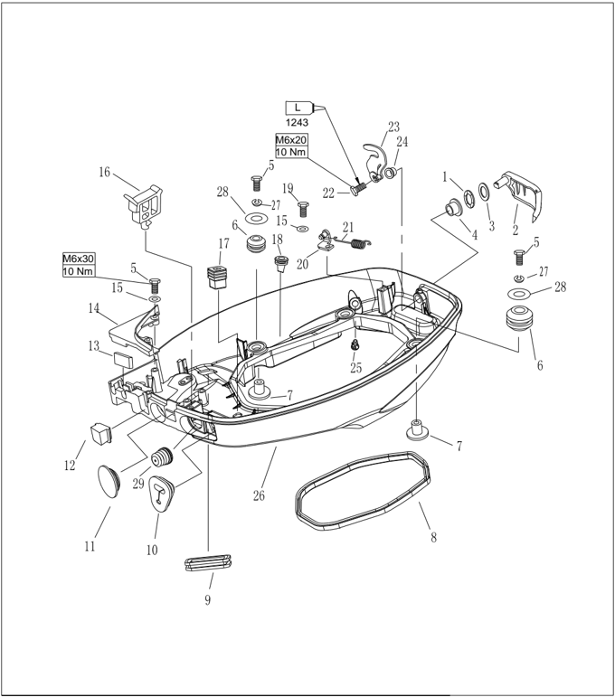
| PART NO. | DESCRIPTION | REMARKS | ||
|---|---|---|---|---|
| 16 | F15-05000008A | CLAMP A | 1 | |
| 17 | F15-05000033 | JACKETLEVER | 1 | |
| 18 | F25-03000005 | NIPPLE,RUBBER | 6 | |
| 19 | GB/T5783-M6x20M6x20 | BOLT, HEXAGON M6x20 | 1 | |
| 20 | F25-03000019 | 1 | ||
| 21 | F15-05000026 | SPRING,TENSION | 1 | |
| 22 | M6x12 GB/T5783-M6x12 | BOLT, HEXAGON M6x12 | 1 | |
| 23 | F25-03020000 | 1 | ||
| 24 | F15-05000036 B | BUSHING B | 1 | |
| 25 | F15-05000009 | NIPPLE,PLASTIC | 1 | |
| 26 | F25-03000001 | BOTTOM COWLING | 1 | |
| 27 | GB/T93-6 | 6 WASHER SPRING 6 | 4 | |
| 28 | 6 F25-00000004 | BIG WASHER 6 | 4 | |
| 29 | F15-05000006 | SHEATH,WAVE | 1 |
Electric Start Type
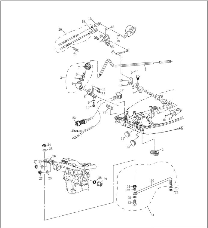
| PART NO. | DESCRIPTION | REMARKS | |
|---|---|---|---|
| 1 | |||
| 2 | |||
| 3 | |||
| 4 | |||
| 5 | |||
| 6 | |||
| 7 | |||
| 8 | |||
| 9 | |||
| 10 | |||
| 11 | |||
| 12 | |||
| 13 | |||
| 14 | |||
| 15 | |||
| 16 | |||
| 17 | |||
| 18 | |||
| 19 | |||
| 20 |
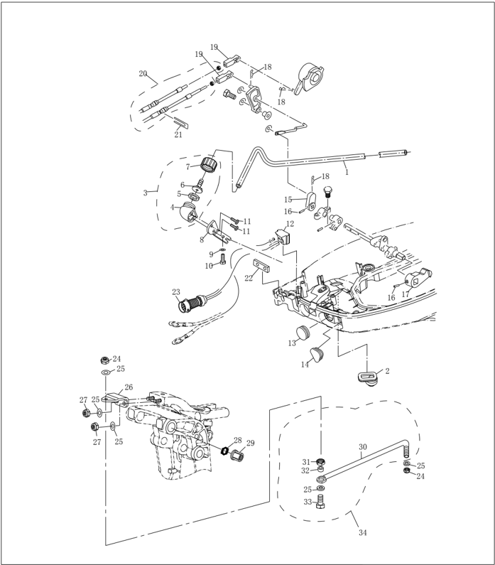
| PART NO. | DESCRIPTION | DESCRIPTION | |
|---|---|---|---|
| 21 | |||
| 22 | |||
| 23 | |||
| 24 | 3/8" | 3/8" | |
| 25 | |||
| 26 | |||
| 27 | |||
| 28 | |||
| 29 | |||
| 30 | |||
| 31 | |||
| 32 | |||
| 33 | |||
| 34 |
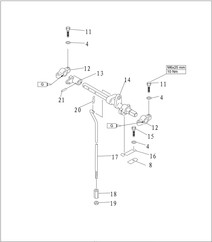
| PART NO. | DESCRIPTION | DESCRIPTION | REMARKS |
|---|---|---|---|
| GB/T5783-M6x25 | M6x25 | BOLT M6x25 | |
| GB/T97.1-6 | 6 | WASHER 6 | |
| F15-05040002 | BRACKET ,SHIFT ROD | ||
| F25-03030001 | ROCKER ,STOPPER | ||
| F15-05040100 | LEVER ,SHIFT ROD | ||
| GB/T5783-M6x20 | M6x20 | BOLT M6x20 | |
| F15-05000031 | SPRING | ||
| F25-03030002 | SHIFT ROD | ||
| F25-03030002 | SHIFT ROD | ||
| F15-05000035 | COLUMNED NUT | ||
| GB/T6172.1-M6 | M6 | NUT M6 | |
| F15-00000012 | SPRING | ||
| GB/T879.4-3x20 | PIN ,SPRING |
Disassembling and Inspection
- Remove rubber plug, wave sheath and throttle cable jacket.
Remove C.D.I. cable assy. (Applicable to model with forward control and electric start).
- Remove bolts fixing bottom cowling cover board, and remove cover board. Remove rubber seal. Remove ringent limitative plate and quadrate rubber plug. (Applicable to model with forward control and electric start).
- Remove top cowling locking handle screws, remove top cowling locking handle and top cowling locking block.
- Remove top cowling locking handle bushing A and top cowling locking handle bushing B.
- Remove wave washer.
- Remove fixing bolt of shift rod bracket.
- Remove cotter pin of shift rod.
- Remove shift rod, spring pin and stopping rocker.
- Remove shift spring plate.
- Inspect bottom cowling for crack or damage. Replace if necessary.
- Inspect top cowling locking handle and top cowling lock block for crack or damage. Replace if necessary.
- Inspect wave washer and locking handle bushing A for crack or damage. Replace if necessary.
- Inspect shift rod bracket and stopping rocker for crack or damage. Replace if necessary.
- Inspect shift spring plate for crack, crank or damage. Replace if necessary.
Steering Handle
Explosive Drawing
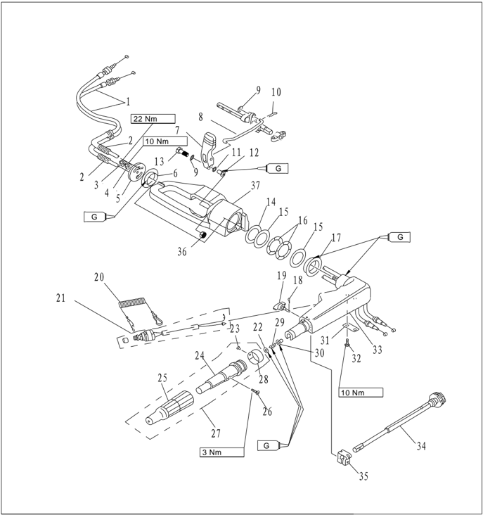
| PART NO. | DESCRIPTION | REMARKS | ||
|---|---|---|---|---|
| 1 | F25-01030101 | |||
| 2 | F25-01030002 | |||
| 3 | LOCKNUT M10x1.25 | |||
| 4 | NUT M10×1.25 | |||
| 5 | F15-01000013 | |||
| 6 | F15-01000011 | () | ||
| 7 | F15-00000007 | |||
| 8 | F25-00000009 | LINK ,SHIFT ROD | ||
| 9 | GB/T97.1-6 | 6 | WASHER ,PLAIN 6 | |
| 10 | F15-00000012 | SPRING ,CLAMP | ||
| 11 | F15-00000009 | WASHER ,WAVE | ||
| 12 | F15-00000008 | TUBE ,FLANGE | ||
| 13 | GB/T5783-M6 x 35 | M6×35 | HEXAGON BOLT M6×35 | |
| 14 | F15-01000012 | WASHER ,NYLON | ||
| 15 | F15-01000008 | WASHER | ||
| 16 | F15-01000009 | WASHER ,WAVE | ||
| 17 | F15-01000007 | () | BUSH ,HANDLE | |
| 18 | GB/T91-1.6x12 | φ1.6×12 | PIN ,COTTER 1.6x12 | |
| 19 | F15-01030200 | BOLT | ||
| 20 | F4-01090401 |
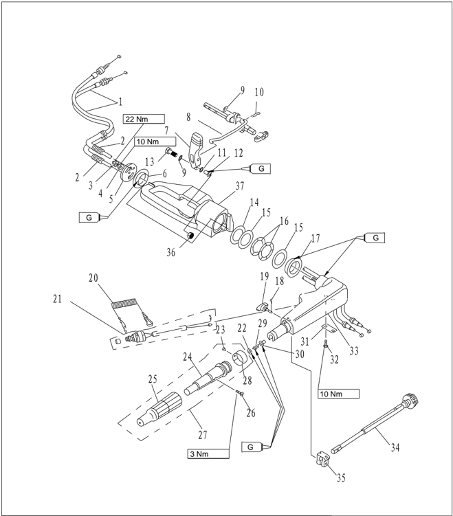
| PART NO. | DESCRIPTION | REMARKS | |||
|---|---|---|---|---|---|
| 21 | T15-01020003 | 1 | |||
| 22 | GB/T848-10 | 10 | SMALL WASHER 10 | 1 | |
| 23 | GB/T827-2 x 5 | 2×5 | 1 | ||
| 24 | F4-01090301 | 1 | |||
| 25 | F4-01090302 | RUBBER ,HANDLE | 1 | ||
| 26 | GB/T820-M5x25 | SCREW M5X25 | 1 | ||
| 27 | F4-01090300 | 1 | |||
| 28 | F4-01090303 | 1 | |||
| 29 | F4-01090007 | 1 | |||
| 30 | F4-01090006 | BUSH | 1 | ||
| 31 | F15-01030005 | STAY | 1 | ||
| 32 | GB/T5783-M6X20 | M6×20 | HEXAGON BOLT M6x20 | 2 | |
| 33 | F15-01030001 | HANDLE STEERING | 1 | ||
| 34 | F15-01030100 | 1 | |||
| 35 | F4-01090003 | FRICTION | 1 | ||
| 36 | GB/T6170-M6 | M6 | NUT M6 | 1 | |
| 37 | F25-01030001 | BRACKET,HANDLE | 1 |
Disassembling and Inspection
- 1. Remove handle bracket , remove gear shift handle, remove steering handle.
- 2. Remove steering handle cover.
- 3. Remove handle bush, bush washer, wave washer.
- 4. Remove cotter pin and friction adjusting bolt.
- 5. Remove steering handle.
- 6. Remove throttle cable.
- 7. Remove throttle lever stay and throttle lever.
- 8. Remove engine stop switch.
- 9. Inspect gear shift handle for crack or damage. Replace if necessary.
- Inspect steering handle for crack or damage. Replace if necessary.
- Inspect bush, bush washer and wave washer for crack or damage. Replace if necessary.
- Inspect throttle cable for wear or crack. Replace if necessary.
- Inspect the conduction of engine stop switch. If not to specification, replace it.
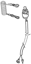
Remove lockplate:
Conducting
Install lockplate:
Not conducting
Push stop switch button: Conducting
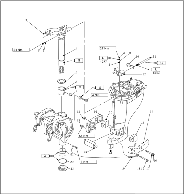
Bracket
Explosive Drawing
| PART NO. | DESCRIPTION | DESCRIPTION | ||
|---|---|---|---|---|
| 1 | GB/T889.2-M8x1.0 | GB/T889.2-M8x1.0 | GB/T889.2-M8x1.0 | 2 |
| 2 | GB/T97.1-8 | 8 | WASHER 8 | 5 |
| 3 | F25-01020002 | 2 | ||
| 4 | F25-01020001 | 1 | ||
| F25-01020001S | 1 | |||
| 5 | F25-01000003 | WASHER ABOVE | 1 | |
| 6 | F25-01000001 | BUSH ABOVE | 1 | |
| 7 | F25-01000002 | PLATE FRICTION | 1 | |
| 8 | GB/T5783-M8x30 | M8×30 | BOLT M8x30 | 3 |
| 9 | GB/T93-8 | 8 | WASHERSPRING 8 | 3 |
| 10 | F25-02000015 | PLATE | 1 | |
| 11 | F25-02000016 | LONG BOLT | 2 | |
| 12 | F25-02030000 | 1 | ||
| 13 | F25-00000005 | M10 | NUT M10 | 4 |
| 14 | F25-00000001 | 2 | ||
| 15 | F25-00000002 | 2 | ||
| 16 | F25-00000006 | M10×120 | BOLT M10x120 | 2 |
| 17 | GB/T97.1-10 | 10 | WASHER 10 | 4 |
| 18 | F25-00000007 | M10×80 | BOLT M10x80 | 2 |
| 19 | F25-02000002 | 1 | ||
| 20 | F25-00000003 | 1 | ||
| 21 | F25-01000004 | BUSH BELOW | 1 | |
| F25-01000004S | BUSH BELOW | 1 | ||
| 22 | F25-01000005 | O | ORING | 1 |
| F25-01000005S | O | ORING | 1 | |
| 23 | F25-01000006 | WASHER BELOW | 1 |
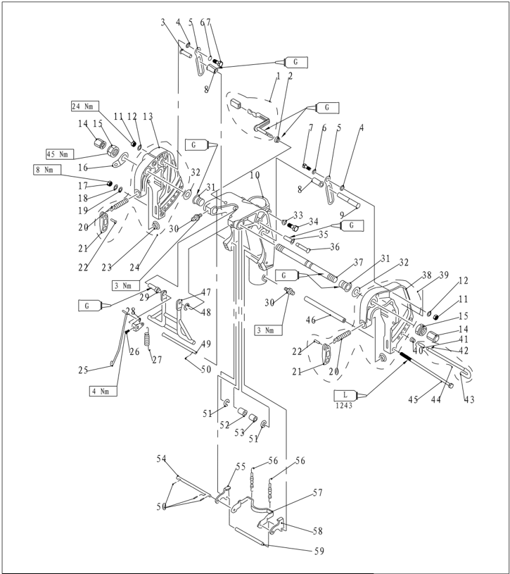
| PART NO. | DESCRIPTION | DESCRIPTION | ||
|---|---|---|---|---|
| 1 | F25-01010312 | F25-01010312 | F25-01010312 | 1 |
| 2 | F25-01010311 | F25-01010311 | WASHER | 1 |
| 3 | F25-01010318 | F25-01010318 | PIN,DETENT(S) | 1 |
| 4 | F25-01010009 | F25-01010009 | WASHER,NYLON | 2 |
| 5 | F25-01010321 | F25-01010321 | PLATE,TILT DETENT | 2 |
| 6 | F25-01010008 | F25-01010008 | WASHER ,WAVE | 2 |
| 7 | F25-01010007 | F25-01010007 | 2 | |
| 8 | F25-01010319 | F25-01010319 | GASKET ,NYLON | 2 |
| 9 | F25-01010322 | F25-01010322 | PIN,DETENT | 1 |
| 10 | F25-01010301 | F25-01010301 | BRACKET ,ROTARY | 1 |
| F25-01010301S | F25-01010301S | BRACKET ,ROTARY | 1 | |
| 11 | LOCKNUT M8 GB/T6182-M8 | LOCKNUT M8 GB/T6182-M8 | LOCKNUT M8 GB/T6182-M8 | 2 |
| 12 | 8 F25-01010010 | 8 F25-01010010 | THICK WASHER | 2 |
| 13 | F25-01010201 | F25-01010201 | BRACKET ,RIGHT | 1 |
| 14 | F25-01010011 | F25-01010011 | NUT PLASTIC | 2 |
| 15 | F15-01010007 | F15-01010007 | 2 | |
| 16 | F25-01010004 | F25-01010004 | PLATE TWO HOLE | 1 |
| 17 | M8 GB/T6170-M8 | M8 GB/T6170-M8 | NUT M8 | 1 |
| 18 | 8 GB/T93-8 | 8 GB/T93-8 | WASHER ,SPRING 8 | 1 |
| 19 | 8 GB/T97.1-8 | 8 GB/T97.1-8 | WASHER 8 | 1 |
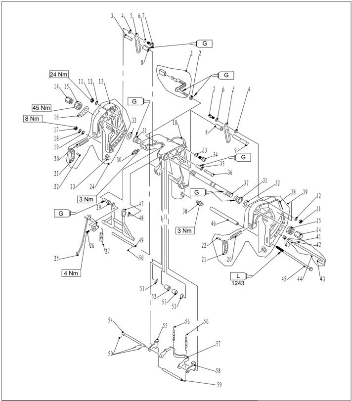
| PART NO. | DESCRIPTION | REMARKS |
|---|---|---|
| F25-01010104 | SCREW ,CLAMP | |
| F25-01010102 | CLAMP HANDLE | |
| F25-01010103 | RIVET | |
| F4-01010003 | CLAMP PLATE | |
| F25-01010200 | ||
| F25-01010315 | ROD BRACKET | |
| GB/T818-M5x6 | ||
| F25-01010314 | SPRING TENSION | |
| F25-01010313 | ||
| F25-01010309 | BUSHING ,HANDLE | |
| GB/T7940.1-M6 | M6 OILCUP M6 | |
| F25-01010002 | BUSH NYLON | |
| F25-01010003 | WASHER | |
| F25-01010302 | WASHER SEAL | |
| F25-01010303 | M8×20 HEXAGON BOLT M8x20 | |
| F25-01010317 | BUSH PIN | |
| F25-01010316 | ||
| F15-01010001 | ||
| F25-01010101 | BRACKET LEFT | |
| F25-01010100 |
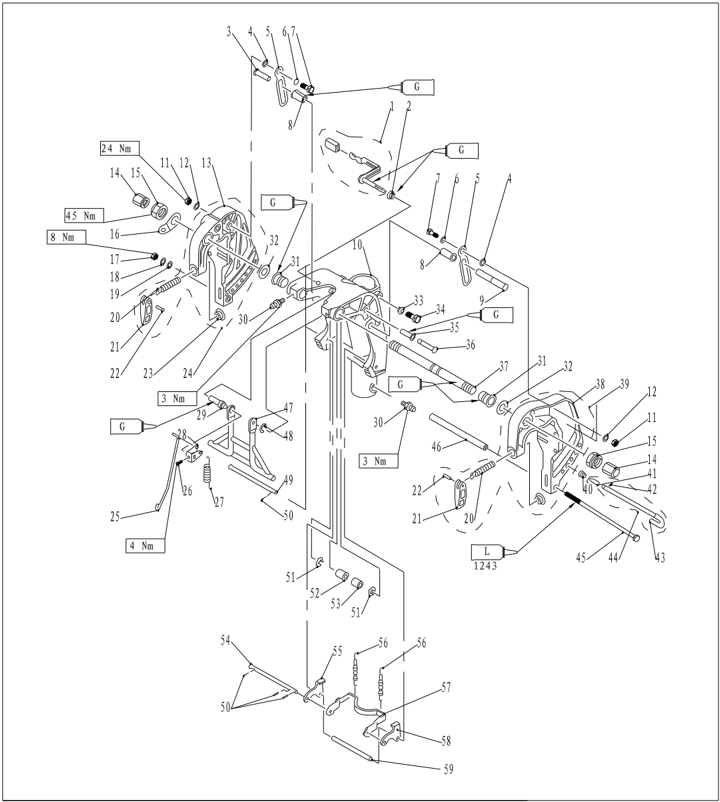
| DESCRIPTION PART NO. | REMARKS | |
|---|---|---|
| F25-01010403 | CONICAL SPRING | |
| F25-01010402 | ||
| GB/T879.2-3x10 | 3×10 PINSPRING 3x10 | |
| F25-01010401 | ||
| F25-01010400 | ||
| F25-01010005 M8×255 | LONG BOLT M8x255 | |
| F25-01010006 | TUBE BOLT | |
| F25-01010308 | SUPPORT ASSY | |
| GB/T896-19868 | CIRCLIP | |
| F25-01010305 | ||
| φ2x12 GB/T91-2x10 | PIN,COTTER 2x10 | |
| GB/T896-9 9 | CIRCLIP 9 | |
| F25-01010324GASKET | NYLON | |
| F25-01010323 | TUBE NYLON | |
| F25-01010307-3 | ||
| F25-01010307-4B | ||
| F25-01010304 | SPRING TENSION | |
| F25-01010307-1 | ARM TILT LOCK | |
| F25-01010307-2A | ||
| F25-01010306 |
Disassembling and Inspection
| 1. | Remove limitative rod and bolt (M6X145). |
|---|---|
| 2 | Remove nut and bolt of tilt stopper plate, and remove the tilt stopper plate. |
| 3 | Remove clamp bracket nut, double hole plate, and double head bolt of clamp bracket. |
| 4 | Remove clamp bracket. |
| 5 | Remove rotary bracket. |
| 6 | Remove lock angle handle and lock bracket rod. Remove tension spring and angle orientation lever. |
| 7 | Remove orientation bushing and nylon bush. |
| 8 | Remove lock angle long shaft and short shaft. |
| 9 | Remove lock angle bracket, torsion spring, tension spring and inner bracket. |
| 10 | Inspect rotary bracket and clamp bracket for damage or crack. Replace if necessary. |
| 11 | Inspect bush and gasket for damage or crack. Replace if necessary. |
| 12 | Inspect lock angle bracket and support bracket for deform. Replace if necessary. |
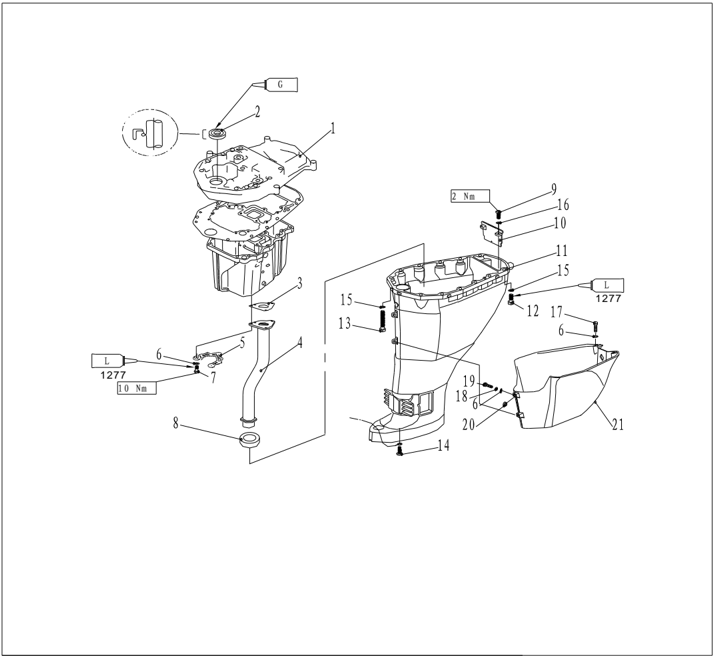
Upper Unit Parts
Explosive Drawing
| PART NO. | DESCRIPTION | REMARKS | |
|---|---|---|---|
| F25-02010001 | GUIDE EXHAUST | ||
| F25-02010002 | OIL SEAL | ||
| F25-02000011 | GASKET,EXHAUST PIPE | ||
| F25-02020000 | EXHAUST PIPE ASSY | ||
| F25-02020000S | EXHAUST PIPE ASSY | ||
| V F25-02000012 | V F25-02000012 | PLATE,"V" | |
| GB/T97.1-6 | 6 | WASHER 6 | |
| GB/T5782-M6x50 | M6x50 | BOLT M6x50 | |
| F25-02000014 | SEAL,EXHAUST PIPE | ||
| GB/T818- M5x16 | M5x16 | SCREW,PAN HEAD M5x16 | |
| F25-02000003 | CLAPBOARD,EXHAUST | ||
| F25-02000001 | UPPER CASING | ||
| F25-02000001S | UPPER CASING | ||
| GB/T5783-M8x30 | M8x30 | BOLT M8x30 | |
| GB/T5782-M8x80 | M8x80 | BOLT M8x80 | |
| GB/T818-M6x10 | M6x10 | ||
| GB/T97.1-8 | 8 | WASHER 8 | |
| GB/T97.1-5 | 5 | WASHER 5 | |
| GB/T5783-M6x14 | M6x14 | BOLT M6x14 | |
| GB/T93-6 | 6 | WASHER,SPRING 6 | |
| GB/T818-M6x25 | M6x25 | SCREW,PAN HEAD M6x25 | |
| GB/T6170-M6 | M6 | NUT M6 | |
| F25-00000200 | MANTLE,UPPER CASING |
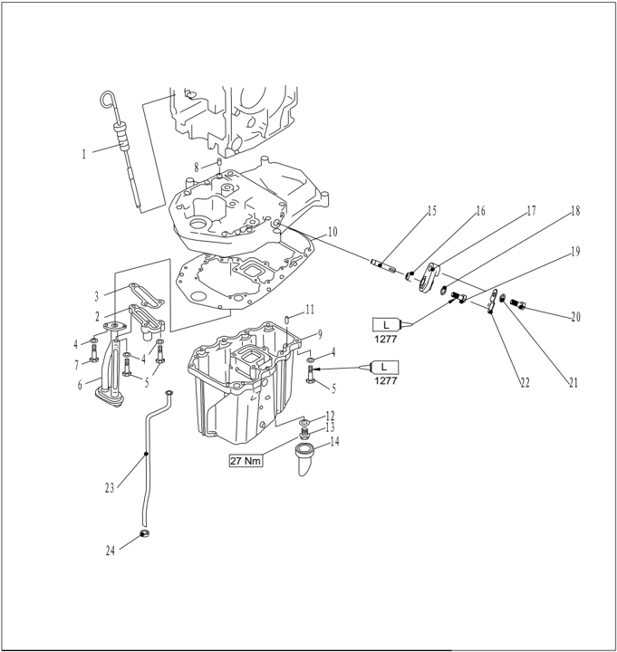
| PART NO. | DESCRIPTION | DESCRIPTION | REMARKS |
|---|---|---|---|
| F25-00000100 | PLUG,OIL LEVEL | ||
| F25-02010100 | RELIEF VALVE AUY | ||
| F25-02010006 | |||
| GB/T97.1-6 | 6 | WASHER,PLAIN 6 | |
| GB/T5783-M6x25 | M6x25 | ||
| F25-02010200 | STRAINER,OIL | ||
| GB/T5783-M6x16 | M6X16 | ||
| F25-00000014 | 8x12 | PIN,DOWEL | |
| F25-02000006 | OIL SUMP | ||
| F25-02010007 | HEXAGON BOLT | ||
| F15-00000006 | 6x12 | PIN,DOWEL 6x16 | |
| F15-04000003 | GASKET | ||
| F15-04000002 | BOLT,OIL DRAIN | ||
| F25-02000007 | JACKET,OIL DRAIN | ||
| F25-02010005 | ANODE | ||
| F15-07010009 | SEAL.ANODE | ||
| F15-07010011 | COVER ,ANODE | ||
| GB/T97.1-5 | 5 | WASHER 5 | |
| GB/T5783-M5x12 | M5x12 | BOLT M5x12 | |
| GB/T5783-M6x20 | M6x20 | BOLT M6x20 | |
| GB/T97.1-6 | 6 | WASHER 6 | |
| F15-07010012 | PLATE ,ANODE | ||
| F25-02000004 | TUPE,WATER | ||
| F25-02000004S | TUPE,WATER | ||
| F25-02000005 |
- Drain the oil.
- Remove upper unit and lower unit fixing bolts, and remove upper unit.
- Remove exhaust guide plate, and remove oil sump.
- Remove exhaust pipe, oil drain bolt, oil drain jacket and exhaust pipe seal from oil sump.
- Remove oil strainer and relief valve auy from exhaust guide plate.
- Remove double hole shock absorber assy, exhaust clapboard, rubber water pipe gasket and water pipe.
- Check the upper casing and oil sump for crack or wear. Replace if necessary.
- Check water pipe for deform or erosion. Replace if necessary.
- Check the relief valve auy for crack or wear. Replace if necessary.
- Check exhaust clapboard for damage, wear or crack. Replace if necessary.
Disassembling and Inspection
Water Pump Assembly
Explosive Drawing
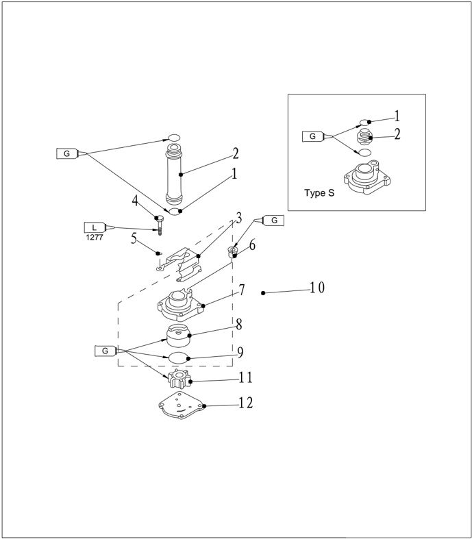
| PART NO. | DESCRIPTION | DESCRIPTION | ||
|---|---|---|---|---|
| 1 | O25.8x2.65 | ORING 25.8x2.65 | 2 | |
| 2 | F25-04000017 | TUBE ,WATER | 1 | |
| F25-04000017S | TUBE ,WATER | 1 | ||
| 3 | F25-04000016 | 1 | ||
| 4 | GB/T5782-M6x40 | M6×40 | BOLT M6x40 | 4 |
| 5 | GB/T97.1-6 | 6 | WASHER 6 | 4 |
| 6 | F25-04050004 | 1 | ||
| 7 | F25-04050001 | 1 | ||
| 8 | F25-04050002 | SHELL ,INNER | 1 | |
| 9 | F25-04050003 | OORING | 1 | |
| 10 | F25-04050000 | 1 | ||
| 11 | F25-04040000 | IMPELLER ASSY | 1 | |
| 12 | F25-04000014 | OUTER PLATE | 1 |
Disassembling and Inspection
- Remove water pump fixed plate.
- Remove water pump shell.
- Remove impeller and water pump inner shell.
- Remove woodruff key and outer plate.
.
- Check water pump shell and outer plate for crack, crank or damage. Replace if necessary.
- Check inner water pump inner shell and impeller for crack, deform, burn or wear. Replace if necessary.
Lower Unit
Explosive Drawing
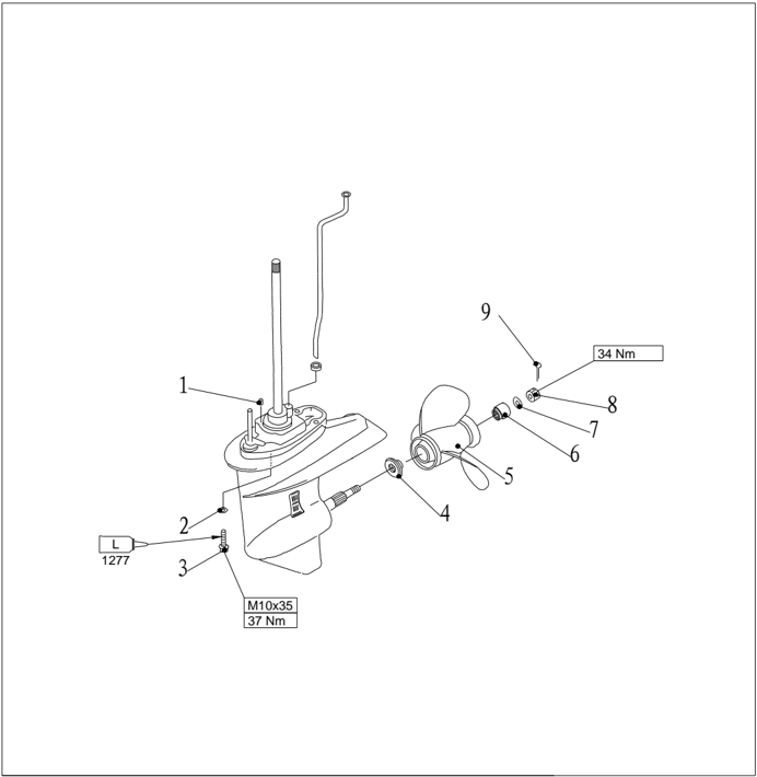
| PART NO. | DESCRIPTION | DESCRIPTION | REMARKS | |
|---|---|---|---|---|
| 1 | F15-00000006 | φ6x12 | PIN,DOWEL | |
| 2 | GB/T97.1-10 | 10 | WASHER 10 | |
| 3 | F25-00000011 | BOLT M10x1.25x35 | ||
| 4 | F25-04000024 | |||
| 5 | F25-04080000 | PROPELLER ASSY | ||
| 6 | F25-04000025 | SPACER | ||
| 7 | GB/T97.1-14 | 14 | WASHER 14 | |
| 8 | F25-04000027 | NUT | ||
| 9 | GB/T91-2.5x22φ2.5x22 |
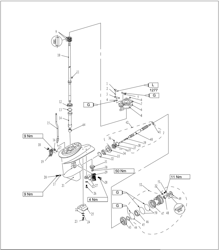
| PART NO. | DESCRIPTION | DESCRIPTION | REMARKS |
|---|---|---|---|
| B/T5783-M6×25 | M6×25 | BOLT M6×25 | |
| GB/T97.1-6 | 6 | WASHER 6 | |
| F25-04000012O | PLATE ,O-RING | ||
| F15-06020004 | O | O-RING | |
| F25-04000013 | WATER SEAL | ||
| F25-04000007 | Φ4x10 | PIN,DOWEL 4x10 | |
| F25-04000008 | BASE ,DRIVE SHAFT | ||
| F25-04000009 | SEAL | ||
| F25-04010003 | 22x36x6 | ||
| F25-04010000 | DRIVE SHAFT ASSY | ||
| F25-04010000S | DRIVE SHAFT ASSY | ||
| F25-04000015 | SEMICIRCULAR KEY | ||
| HOUSING,BEARING | |||
| F25-04000003-1 | SHIM(t:0.7mm) | ||
| F25-04000003-2 | SHIM(t:1.0mm) |
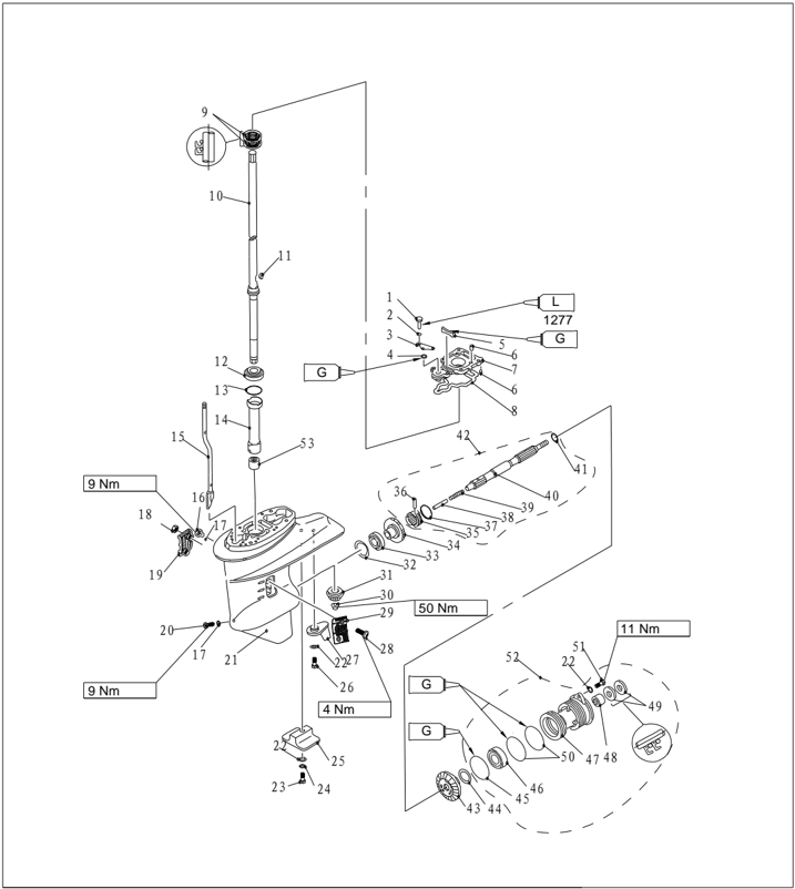
| PART NO. | DESCRIPTION | |||
|---|---|---|---|---|
| F25-04000003-3 | SHIM(t:1.1mm) | |||
| F25-04000003-4 | SHIM(t:1.2mm) | |||
| F25-04000003-5 | SHIM(t:1.3mm) | |||
| F25-04000003-6 | SHIM(t:1.4mm) | |||
| F25-04000003-7 | SHIM(t:1.5mm) | |||
| F25-04000003-8 | SHIM(t:1.6mm) | |||
| 14 | F25-04000002 | BUSHING ,NYLON | 1 | |
| 15 | F25-04030000 | 1 | ||
| F25-04030000S | 1 | |||
| 16 | F4-03000023 | PLUG,HOLE OIL | 1 | |
| 17 | F4-03000024 | GASKET | 2 | |
| 18 | GB/T889.1-M5 | NUT,LOCKING M5 | 2 | |
| 19 | F25-04000023 | B | WATER INLET "B" | 1 |
| 20 | F25-04000031 | PLUG,DRAIN | 1 | |
| 21 | F25-04000001 | LOWER CASING | 1 | |
| 22 | GB/T97.1-6 | 6 | WASHER 6 | 4 |
| 23 | GB/T5782-M6x35 | M6×35 | BOLT M6×35 | 1 |
| 24 | GB/T861.1-6 | 6 | WASHER,LOCKING 6 | 1 |
| 25 | F15-06000004 | ANODE,LOWER | 1 | |
| 26 | GB/T5783-M6x20 | M6×20 | BOLT M6×35 | 1 |
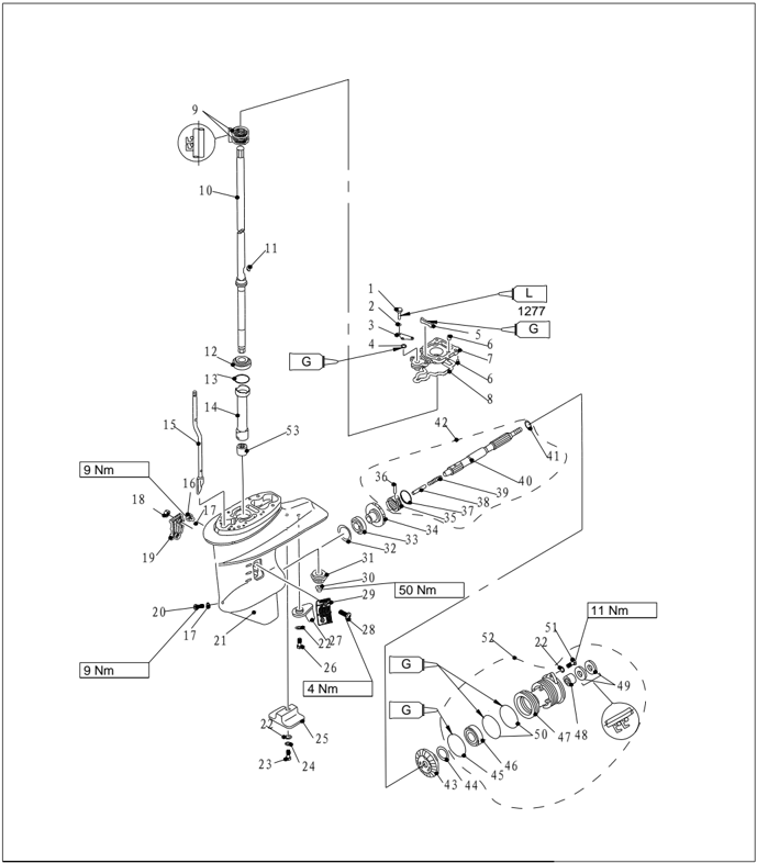
| PART NO. | DESCRIPTION | DESCRIPTION | REMARKS | ||
|---|---|---|---|---|---|
| 27 | F25-04000021 | TAB,COURSE | 1 | ||
| 28 | GB/T820-M5x30 | 1 | |||
| 29 | F25-04000022 | A | WATER INLET "A" | 1 | |
| 30 | F25-04000006 | NUT,PINION | 1 | ||
| 31 | F25-04000005 | PINION | 1 | ||
| 32 | F25-04000004-1 | SHIM(t:1.0mm) | |||
| F25-04000004-2 | SHIM(t:1.1mm) | ||||
| F25-04000004-3 | SHIM(t:1.2mm) | ||||
| F25-04000004-4 | SHIM(t:1.3mm) | ||||
| F25-04000004-5 | SHIM(t:1.4mm) | ||||
| 33 | 1 | ||||
| 34 | F25-04020000 | GEAR,FORWARD | 1 | ||
| 35 | F25-04060003 | CLUTCH, DOG | 1 | ||
| 36 | F15-06070004 | PINCLUTCH | 1 | ||
| 37 | F15-06070005 | RINGCLUTCH | 1 | ||
| 38 | F25-04060006 | PLUNGER, SHIFT | 1 | ||
| 39 | F25-04060002 | SPRING, CLUTCH | 1 | ||
| 40 | F25-04060001 | SHAFT, PROPELLER | 1 | ||
| 41 | F25-04060007 | 1 | |||
| 42 | F25-04060000 | 1 |
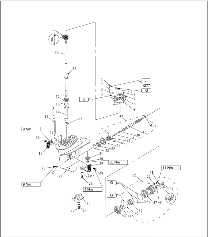
| PART NO. | DESCRIPTION | REMARKS | ||
|---|---|---|---|---|
| 43 | F25-04070004 | GEAR, REVERSE | 1 | |
| 44 | F25-04070005-1 | SHIM(t:1.0mm) | ||
| F25-04070005-2 | SHIM(t:1.1mm) | |||
| F25-04070005-3 | SHIM(t:1.2mm) | |||
| F25-04070005-4 | SHIM(t:1.3mm) | |||
| 45 | F25-04070002 | O-RING A | 1 | |
| 46 | KOYO 6006C3 | BALL BEARING | 1 | |
| 47 | F25-04070001 | 26x20x16 ROLLER GEARING | 1 | |
| 48 | 20x34x6.5 OIL SEAL 20x34x6.5 | 1 | ||
| 49 | F25-04070006 | 2 | ||
| 50 | F25-04070003 | O-RING B | 2 | |
| GB/T5783-M6x20 | BOLT M6x20 M6x20 | 2 | ||
| 52 | F25-04070000 | 1 | ||
| 53 | F2020 | NEEDLE BEARING | 1 |
Disassembling and Inspection
- Drain oil, and remove the cotter pin.
- Put a piece of wood between propeller and anti-swirl baffle. Remove hexagon nut, anode and water inlet.
- Remove propeller assembly and cushion.
- Remove anode.
- Remove the lower casing cover. Remove reverse gear and shim. Remove oil seal.
- Remove propeller shaft assembly.
- Remove shift plunger.
- Remove clutch ring, remove clutch pin and dog clutch. Remove clutch spring.
- Remove drive shaft base.
- Remove the pinion nut by using female spline spanner. Remove drive shaft. Remove drive shaft nylon bushing..
- Remove shift rod cam assy and forward gear.
- Remove rolling needle bearing from lower unit.
- Remove oil seal from the drive shaft base, and remove the bearing from forward gear.
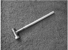
Propeller Shaft and Clutch Block
- Check dog clutch for crack or damage. Replace if necessary.
- Check propeller shaft for wear or crank. Replace if necessary.
- Check the run out of propeller shaft. If out of specification, replace.
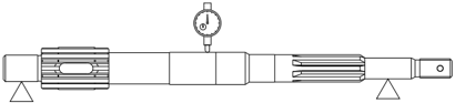
: 0.02 mm
Dog Clutch Installation
- Put clutch spring into the hole at the end of the propeller shaft.
Run out limit
- Install the dog clutch as shown. Make sure the 'F'or '●' mark is toward the forward gear. Install clutch pin.
- Install clutch ring and shift plunger.
- Install oil seal.
- Install new bearing on the reverse gear.

NOTE:
Install oil seal and bearing by using special tools.
Take note of the direction and depth when installing.
Make sure the manufacturer mark of the bearing is toward the reverse gear.
Installing depth:
Lower casing cover bearing installer
| Needle Bearing | Needle Bearing | 31.0~31.5mm |
|---|---|---|
| Depth1 | 13.0~13.5mm | |
| Depth2 | 6.0~6.5mm |
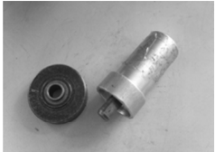
Lower casing cover oil seal installer
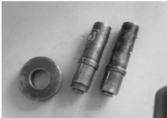
Lower Casing Cover
- Check bearing for rust or rumbling when run. Replace if necessarily.
- Remove bearing and oil seal by bearing puller.
NOTE:
Don't remove bearing unless changing it.
- Remove rolling needle bearing by using special tool.
NOTE:
Use new parts when reinstalling the oil seal and rolling needle bearing.
- Clean casing cover by a soft brush and solvent.
- Check casing cover for crack or damage. Replace if necessary.
Lower Casing Cover Oil Seal and Bearing Installation
Lower casing cover needle bearing installer
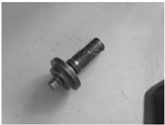
- Install reverse gear and shim.
NOTE:
Adjust the shims when install the new reverse gear and bearing.
Drive Shaft
- Inspect the drive shaft for crank or wear. Replace if necessary.
- Check the run out of drive shaft.

Run out limit: 0.05 mm
Reverse gear bearing installer
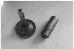
Shift Rod Cam
Check the shift rod cam for wear or deform. Replace if necessary.
Gear
Inspect the forward gear, reverse gear and pinion for wear or damage. Replace if necessary.
Forward Gear Bearing
Inspect bearing for rust or rumbling when rotating. Replace if necessary.
NOTE:
Don't remove bearing unless replace it.
Adjust the shim when install new bearing.
Lower Casing Inspection
Check lower casing for crack or damage, check cooling water inlet for clog. Replace if necessary.
Assembling Lower Casing
- Install the rolling needle bearing by using special tool.
Rolling needle bearing installer
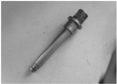
- Install new forward gear bearing (if replace).
- Install drive shaft base oil seal.
- Install nylon bushing, shift rod cam assy, gasket, and drive shaft base. Install forward gear, drive shaft, shim, and pinion.
Forward gear bearing housing installer
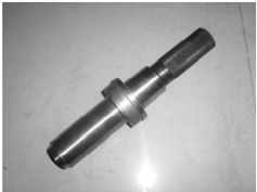
Drive shaft oil seal installer
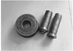
CAUTION:
Adjust shim when install new drive shaft base or drive shaft.
- Tighten the pinion nut. Specified torque: 50Nm
- Install propeller shaft assy.
- Install lower casing cover.
- Check if gearshift works normally.
Lower casing cover installer
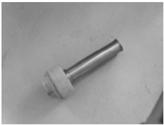
- Install water pump assy.
- Install anode and water inlet.
- Install propeller and hexagon nut. Put a piece of wood between propeller and anti-swirl baffle. Tighten the nut according to specified torque.
Specified torque: 34Nm
NOTE:
If the nut slot is not aligned with the hole of the propeller shaft cotter pin, tighten the nut until aligned.
Lower Unit Installation
- Install dowel pin.
- Move the shift rod cam assy to reverse gear position. Install the lower unit to upper casing, tighten the bolts according to specified torque. Specified torque: 37 Nm
- Connect the columned nut and shift rod cam assy. Change shift, and check if the operation is normal. Adjust the columned nut position if necessary. Tighten the nut thoroughly.
- Add gear oil using the pressure filling device.
Shim Selection
Adjust the shim when replacing the spare parts in lower unit or assembling a new lower unit.
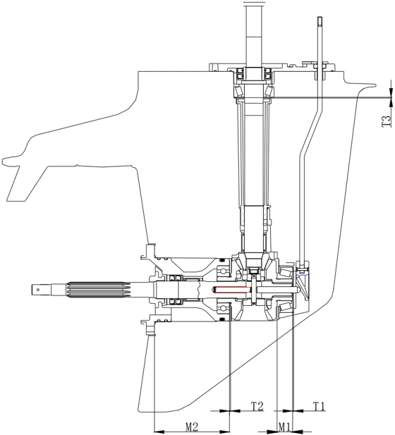
Pinion Shim
- Install drive shaft onto special tool. Install pinion and tighten it according specified torque. Specified torque: 50 Nm
- Mearsure the clearance between special tool and pinion by clearance gauge, and calculate the thickness of T3 according to the formula. Calculation formula: T3=M3
- Select the shim according to the table below.
| T3 | T3 | Shim size selection |
|---|---|---|
| From | To | Shim size selection |
| 1.10 | 1.20 | 1.2 |
| 1.20 | 1.30 | 1.3 |
| 1.30 | 1.40 | 1.4 |
| 1.40 | 1.50 | 1.5 |
| 1.50 | 1.60 | 1.6 |
| 1.60 | 1.70 | 0.7+1.0 |
| 1.70 | 1.83 | 0.7+1.1 |
| Optional shim size: 0.7, 1.0, 1.1, 1.2, 1.3, 1.4, 1.5, 1.6 | Optional shim size: 0.7, 1.0, 1.1, 1.2, 1.3, 1.4, 1.5, 1.6 | Optional shim size: 0.7, 1.0, 1.1, 1.2, 1.3, 1.4, 1.5, 1.6 |
Unit: mm
Forward Gear Shim
- Rotate the outer ring of forward gear, to make the roller fall completely inside the bearing housing.
- Measue the height of bearing, calculating the thickness of T1 according to formula. Calculation formula: T1=17.5-M3
NOTE:
Use three measuring points to measure the thickness.
Apply the average.
- Select the shim according the table below.
| T1 | T1 | Shim size selection |
|---|---|---|
| From | To | Shim size selection |
| 0.99 | 1.10 | 1.0 |
| 1.10 | 1.20 | 1.1 |
| 1.20 | 1.30 | 1.2 |
| 1.30 | 1.40 | 1.3 |
| 1.40 | 1.50 | 1.4 |
| Optional shim size: 1.0, 1.1, 1.2, 1.3, 1.4 | Optional shim size: 1.0, 1.1, 1.2, 1.3, 1.4 |
Unit: mm
- Special tool
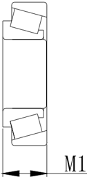
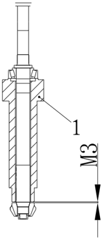
Reverse Gear Shim
- Measure the size according to picture below.
- Calculate the thickness of T2 according to formula.
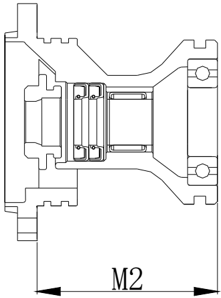
Calculation formula: T2=80-M2
- Select the shim according the table below.
| T2 | T2 | Shim size selection |
|---|---|---|
| From | To | Shim size selection |
| 0.99 | 1.10 | 1.0 |
| 1.10 | 1.20 | 1.1 |
| 1.20 | 1.30 | 1.2 |
| 1.30 | 1.32 | 1.3 |
| Optional shim size: 1.0, 1.1, 1.2, 1.3 | Optional shim size: 1.0, 1.1, 1.2, 1.3 |
Unit: mm
Common Troubles and Solutions
| Trouble type | Possible reason | Recovery action |
|---|---|---|
| Starter will not operate | Starter components are faulty | Repair or replace |
| Starter will not operate | Shift lever is not in the neutral position | Move to the neutral position |
| Engine will not start | Fuel tank is empty | Fill tank with clean, fresh fuel |
| Engine will not start | Fuel is contaminated or stale | |
| Engine will not start | Fuel cleaner is obstructed | Replace fuel cleaner |
| Engine will not start | Fuel pump is faulty | Inspect or replace |
| Engine will not start | Air vent screw on fuel tank is not loosened | Loosen air vent screw |
| Engine will not start | Spark plug(s) fouled or of incorrect type. | Inspect spark plug(s). Clean or replace with recommended type |
| Engine will not start | Spark plug cap(s) fitted incorrectly | Check and re-fit cap(s) |
| Engine will not start | Ignition wiring is faulty | Check wires. Tighten all loose connections. Replace worn or broken wires |
| Engine will not start | Ignition parts are faulty | Replace |
| Engine will not start | Engine stop switch lanyard is not attached | Attach lanyard |
| Engine will not start | Engine inner parts are damaged | Repair |
| Engine idles irregularly or stalls | Spark plug(s) fouled or of incorrect type. | Inspect spark plug(s). Clean or replace with recommended type |
| Engine idles irregularly or stalls | Fuel system is obstructed | Check for pinched or kinked fuel line or other obstructions in fuel system |
| Engine idles irregularly or stalls | Fuel is contaminated or stale | Fill tank with clean, fresh fuel |
| Engine idles irregularly or stalls | Fuel cleaner is obstructed | Replace |
| Engine idles irregularly or stalls | Spark plug clearance is incorrect | Inspect and adjust as specified |
| Engine idles irregularly or stalls | Ignition wiring is faulty | Check wires. Tighten all loose connections. Replace worn or broken wires |
| Engine idles irregularly or stalls | Specified engine oil is not being used | Check and replace oil as specified |
| Engine idles irregularly or stalls | Thermostat is faulty | Replace |
| Engine idles irregularly or stalls | Carburetor is faulty | Replace |
| Engine idles irregularly or stalls | Fuel pump is faulty | Replace |
| Engine idles irregularly or stalls | Air vent screw on fuel tank is not loosened | Loosen air vent screw |
| Engine idles irregularly or stalls | Choke knob is pulled out | Return to home |
| Engine idles irregularly or stalls | position | |
| Engine idles irregularly or stalls | Motor angle is too high | Return to normal operating position |
| Engine power loss | Propeller is damaged | Repair or replace propeller |
| Engine power loss | Trim angle is incorrect | Adjust trim angle to achieve most efficient angle |
| Engine power loss | Motor is mounted at incorrect transom height | Adjust motor to proper transom height |
| Engine power loss | Boat bottom is fouled with marine growth | Clean boat bottom |
| Engine power loss | Weeds or other foreign matter are tangled on gear housing | Remove foreign matter and clean lower unit |
| Engine power loss | Spark plug(s) fouled or of incorrect type. | Inspect spark plug(s). Clean or replace with recommended type |
| Engine power loss | Fuel system is obstructed | Check for pinched or kinked fuel line or other obstructions in fuel system |
| Engine power loss | Fuel cleaner is obstructed | Replace fuel cleaner |
| Engine power loss | Fuel is contaminated or stale | Fill tank with clean, fresh fuel |
| Engine power loss | Spark plug clearance is incorrect | Inspect and adjust as specified |
| Engine power loss | Ignition wiring is faulty | Check wires. Tighten all loose connections. Replace worn or broken wires |
| Engine power loss | Ignition parts have failed | Replace |
| Engine power loss | Specified engine oil is not being used or oil is added too much | Check and replace oil as specified, or adjust engine oil to specified position |
| Engine power loss | Thermostat is faulty | Replace |
| Engine power loss | Fuel pump is faulty | Replace |
| Engine power loss | Fuel joint connection is incorrect | Connect correctly |
| Engine power loss | Specified spark plug(s) are not being used | Check and replace spark plug(s) as specified |
| Engine vibrates excessively | Propeller is damaged | Repair or replace propeller |
| Engine vibrates excessively | Propeller shaft is damaged | Replace |
| Engine vibrates excessively | Weeds or other foreign matter are tangled on propeller | Remove and clean propeller |
| Engine vibrates excessively | Motor mounting bolt is loose | Tighten bolt |
| Engine vibrates excessively | Steering pivot is loose | Tighten steering pivot |
| Engine vibrates excessively | Steering pivot is damaged | Replace |