
Parsun F9.9/F15 Outboard Engine Service Manual
Table of Contents
General Information
Identification
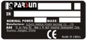
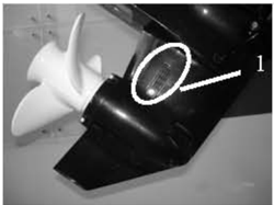
The outboardmotor serial number is marked onthe label.The label can be found on thebracket left assembly or on the upper part of the bracket swivel.Record your outboard motor serial number in the your outboard motor is stolen.
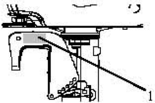
- 1.Outboard motor serial numberlocation
Serialnumberasfollows:

Propeller Selection
The performance of your outboard motor will be critically affected by your choice of propeller, as an incorrect choice could adversely affect performance.
a large-pitch propeller is more suitable for a smaller operating load as it enables the correct engine speed tobe maintained.
When the engine is running at full throttle position, the suitable propeller should be used according to the engine's RPM and the fuel capability.So the outboard engine can supply the best performance.
| Propeller sizes | Material |
|---|---|
| 91/4×8 91/4×11 | Alurminum alloy |
Emergency Start
- The start program can only be used in Emergency and to return to harbor for repairing.
- working.So please ensure the shift rod is in NEUTRAL position.
- items far away.Don't touch flywheel or other moving parts.
- When starting and operating, don't touch ignition coil, spark plug cap or other electric parts.
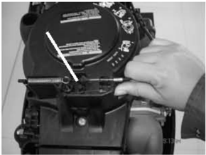
The procedure is as follows:
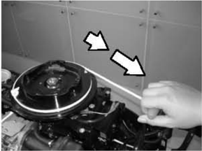
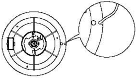
- 2.Remove the start-in-gear protection device cable.
- 1.Remove the top cowling.
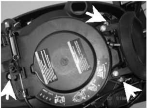
- 3.Demount three bolts and remove starter.
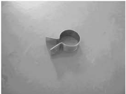
- 4.Insert the knot of the cable in the notch of flywheel rotor, and wind the cable around flywheel several rounds in clockwise direction..
- 5.Pull the manual starter handle slowly until you feel resistance.
- 6.Give a strong pull to start the engine. Repeat if necessary.
Safety While Working
To prevent the danger or accidents when performing maintenance and repair, and improve the work efficiency, please obey the following safety procedures.
1. Fire Prevention
Gasoline (petrol), lubricant and grease are highly flammable.While working, keep away from heat, sparks and open flames.
- Start-in-gear protection device cable
2. Ventilation
Petroleum vapor and engine exhaust gases are violent in toxicity.They are harmful to breathe and deadly if inhaled in large quantities. When test-running an engine indoors, maintain good ventilation.
3. Self-Protection
Protect your eyes with suitable safety glasses or safety goggles, when drilling, grinding or operating air compressor. Protect hands and feet by wearing protective work clothes, safety gloves and shoes if necessary.
4. Lubricants and Sealing Fluids
When performing maintenance procedures and repair to Parsun outboards, use only products provided or recommended by our Company.
Undernormalconditionsofuse,thereshouldbenohazardsfromtheuseofthelubricants mentioned in this manual, but safety is all-important, and by adopting good safety practices, any risk is minimized.
- ①To protect the skin, the application of a suitable barrier cream to the hands before working is recommended.
- ② Clothing which has become contaminated with lubricants should be changed as soon as practicable,and washed before further use.
- ③ Avoid skin contact with lubricants.
- ④ Hands and any other part of the body which have been in contact with lubricants or lubricant-contaminated clothing, should be thoroughly washed with hot water and soap as soon as practicable.
- A supply of clean lint-free cloths should be available for wiping run-off lubricants or grease.
5. Good Working Practices
- ① Follow the tightening torque instruction. When tightening bolts, nuts and screws, tighten the large sizes first, and tighten inner-positioned fixings before outer-positioned ones.
- ② Use the recommended special tools to protect parts from damage.Use the right tool in the right manner.
Disassembly and Assembly
When disassembly and assembly, please follow the following principles:
- Use special tools when disassembling and assembling.
- Clean dirt before disassembling the parts.
- Oil the contact surfaces of moving parts before assembly.
- 4.Install bearing with the manufacturer's markings on the side exposed to view and liberally oil the bearing.
- When installing oil seals, apply a light coating of water-resistant grease to the ledge and outside diameter.
- 6.After assembly, check if the moving parts operate normally.
One-Time Use Parts
One-time use parts are gasket, oil seal, O-ring, cotter pin and spring, ring, and etc.. When re-assembling outboard engine, you must change the one-time use parts.
Pre-Delivery Check
To ensure the using, please inspect the following before delivery.
- 1.CHECKINGFUELSYSTEM
Check if the fuel pipe is connected firmly, and if the fuel tank is filled with fuel.
CAUTION:
Do not use pre-mixed fuel for this 4 stoke outboard engine.
2. Checking Oil Level
- Check the engine oil level Remove oil cap, check engine oil level.
1.Oil cap 2. High position mark 3.Low position mark
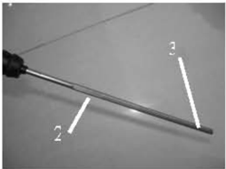
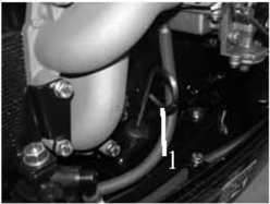
Ensure the oil level between the marks of upper and lower. If above upper level, drain engine oil; if below lower mark, add engine oil up to upper level.
- ② Check the gear oil level
Remove the oil level plug. Check if the gear oil overflows at the oil level checking hole. If so, install the oil level plug and tighten it according to specified torque.Otherwise please add gear oil.
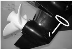
- Oil level plug
3. Check Steering System
Check if steering is stable. Check if steering friction is adjusted correctly. Turn clamphandle screw clockwise toincrease resistance.
Turn clamp handle screw counter clockwise to lower resistance.
4. Check Shift Lever and Throttle
Check if the shift lever is operated smoothly.
Check if the throttle grip is turned smoothly from full closed position to full open position.
5. Check Engine Stop Switch Assembly
Check if the engine stops when pushing the engine stop switch assembly or pulling out the stopper hang rope.
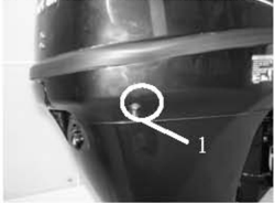
6. Check Cooling Water Checking Hole
When the engine is running, check if cooling water overflows at the cooling water checking hole.
- Cooling water checking hole
7. Breaking-In Running
- ① Initial 1 hour: operate the engine at 2000 r/min or about a half throttle.
- ? The following 8 hours: operate the engine at full throttle continuously. Each operation time doesn't exceed 5 minutes.
- ② The second hour: operate the engine at 3000 r/min or about 3/4 throttle.
8. Inspection After Breaking-In Running
- ① Check if gear oil contains water..
- ② Check if the fuel line leaks.
- ③ After breaking-in running, operate the engine at idling speed. Use cleaning tool to wash over the cooling water passage by fresh water.
9. After Breaking-In Running, Inspect Idling Speed
- ① Preheating engine for 5 minutes.
- ② Using the tachometer to measure idling speed RPM. If out of specification, adjust it. Idling speed: 900~1000 r/min.
- ③ Turn the throttlestopscrewclockwise or counterclockwise until the specified idling speed is attained.
- 4 After adjusting idling speed, picking up RPM several times to check the engine's stability.
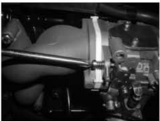
- Clamp handle screw
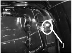
Special Tools and Detection Device
When performing maintenance and repair, you need to use all kinds of special tools and detection device. The use of correct tools will improve the work efficiency and avoid of the damage to the people and outboard engines.
Special Tools
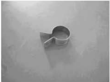
Piston slider
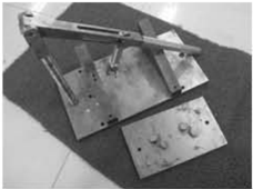
Valve spring compressor
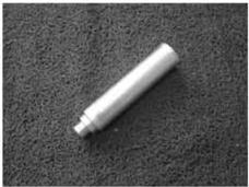
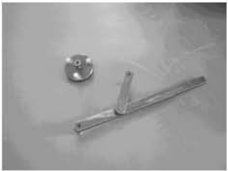
Flywheel gripper and puller
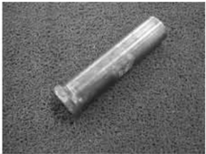
Housing oil seal installer
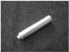
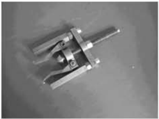
Bearing puller
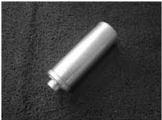
Lowercasingcoverbearinginstaller
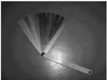
Lower casing coverbarrel bearing installer,Lower casing cover oil seal installer
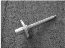
Needle bearing installer
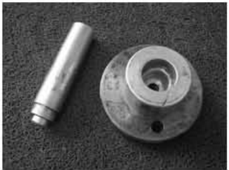
Bearingblockoilsealinstaller
Oil cleaner spanner
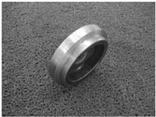
Forward gear bearing installer
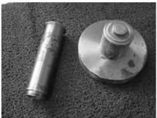
Space gage
Bearingblockcopper sleeve installer
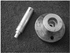
Detection Device
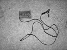
Digital tachometer
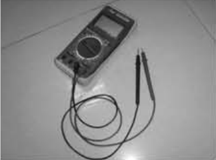
Digital circuit tester
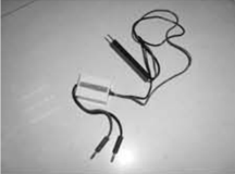
Peak voltage adaptor
Explosive Drawing and Symbol
Explosive Drawing
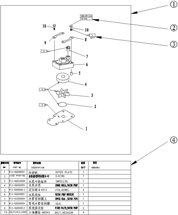
- 1 Parts explosive drawing.
- Screw specification and specified torque.
- Oil, fluid sealant or locking substance daubing point.
- Spare parts details.
Symbol

Specifications
Outboard Engine Specifications
| Item | Item | Item | Description | Item | Item | Description |
|---|---|---|---|---|---|---|
| Dimension | Overall length | Overall length | 1001mm | Unit Power | Ignition system | C.D.1 |
| Dimension | Overall width | Overall width | 427mm | Unit Power | Starting enrichment | Choke valve |
| Dimension | Overall height | S | 1080mm | Unit Power | Spark plug | DPR7HS |
| Dimension | Overall height | L | 1207mm | Unit Power | Exhaust system | Under water |
| Weight | S | S | 49kg | Unit Power | Lubrication system | Pressurelubrication |
| Weight | L | L | 51kg | and Fuel | Fuel type | Unleaded regular gasoline |
| Performance | Max output | Max output | 7.3Kw(9.9hp)@5000r/min | and Fuel | Fuel standard Fuel tank capacity | PON86、RON91 |
| Performance | Full throttle | Full throttle | 4500~5500r/min | and Fuel | Fuel standard Fuel tank capacity | PON86、RON91 |
| Performance | operation Max fuel consumption | operation Max fuel consumption | and Fuel | Recommended engine oil | APISE,SF,SG,SH, SJ SAE 10W30, 10W40 | |
| Performance | 3.5L/h@5500r/min(7.3Kw) 5.3L/h@5500r/min(11Kw) | and Fuel | Engine oil quantity | 1.2L | ||
| Performance | Idle speed (Neutral) | Idle speed (Neutral) | 950±50r/min | and Fuel | Recommended gear oil | Hypoid gear oil SAE 06# |
| Unit Power | Type | Type | 4 stroke, OHV | and Fuel | Gear oil quantity | 250 cm3 |
| Unit Power | Number of cylinders | Number of cylinders | 2 | Bracket | Tilt angle | 8°12°16°20° |
| Unit Power | Displacement | Displacement | 323cm3 | Bracket | Tilt-up angle | 63° |
| Unit Power | BorexStroke | BorexStroke | 59mm×59mm | Bracket | Steering angle | 45°+40° |
| Unit Power | Compression ratio | Compression ratio | 9.19:1 | Unit Drive | Gear positions | F-N-R |
| Unit Power | Min.compression pressure | Min.compression pressure | 765kPa | Unit Drive | Gear ratio | 2.08 |
| Unit Power | Number of carburetors | Number of carburetors | 1 | Unit Drive | Gear type | Spiral bevel gear |
| Unit Power | Control system | Control system | Tiller control | Unit Drive | Clutch type | Dog clutch |
| Unit Power | Starting system | Starting system | Recoil starter | Unit Drive | Propeller drive system | Spline |
Maintenance Information
Power Unit
| Item | Description | Item | Description | ||||
|---|---|---|---|---|---|---|---|
| Head Cylinder | Warp limit | 0.1mm | Valve | Valve | Intake | 0.15~0.25mm | |
| Camshaft inside diameter | 35.000~35.012mm | clearance (cold) | Exhaust | 0.20~0.30mm | |||
| Rocker shaft outside diameter | 12.941~12.951mm | Face width | Intake | 1.98~3.11mm | |||
| Rocker inside diameter | 13.000~13.018mm | Exhaust | 1.98~3.11mm | ||||
| Cylinder | Bore | 59.00~59.015mm | Seat width | Intake | 0.6~0.8mm | ||
| Wearlimit | 59.1mm | Exhaust | 0.6~0.8mm | ||||
| Taper limit | 0.08mm | Margin | Intake | 0.50~0.90mm | |||
| Out of round limit | 0.05mm | thickness | Exhaust | 0.50~0.90mm | |||
| Piston | Piston diameter | 58.950~58.965mm | Head diameter | Intake | 27.9~28.1mm | ||
| Measuring point height | 5mm (from the bottom of piston) | Exhaust | 21.9~22.1mm | ||||
| Piston-to-cylinder clearance | 0.035~0.065mm | Stem outside diameter | Intake | 5.475~5.490mm | |||
| Pin boss inside diameter | 14.004~14.015mm | Exhaust | 5.460~5.475mm | ||||
| Piston pin outside diameter | 13.996~14.000mm | Guide inside diameter | Intake | 5.500~5.512mm | |||
| ring Piston | ring doL | Thickness | 1.17~1.19mm | Exhaust | |||
| Breadth | 2.0~2.20mm | 0.025~0.052mm | |||||
| End gap | 0.15~0.30mm | Stem toguideclearance | |||||
| Side | 0.04~0.08mm | Stem roundness limit | 0.01mm | ||||
| clearance Thickness | 1.47~1.49mm | Rocker shaft outsidediameter | 12.941~12.951mm | ||||
| ring | Breadth | 2.50~2.70mm | Rocker inside diameter | 13.000~13.018mm | |||
| 2nd | End gap | 0.30~0.50mm | Free length | 34.40mm | |||
| clearance | Side | 0.02~0.04mm | alve | Free length limit | 32.68mm | ||
| Thickness | 2.31~2.51mm | Tilt limit | 1.5mm | ||||
| Breadth | 2.30~2.60mm | rod Connecting | Small end inside diameter. | 14.015~14.029mm | |||
| I ring | End gap | 0.20~0.70mm | Big end inside diameter. | 31.031~31.042 mm | |||
| Side clearance | 0~0.22mm | Big end oil clearance | 0.021~0.045mm |
| Camshaft | Height | Intake | 27.596~27.696mm | Journal diameter | 34.997~35.009mm | |
|---|---|---|---|---|---|---|
| Camshaft | Height | Exhaust | 27.616~27.716mm | Crankpin diameter | 30.997~31.009mm | |
| Camshaft | Round diameter | Round diameter | 23.950~24.050mm | Crankpin width | 21.00~21.07mm | |
| Camshaft | Journal diameter | Journal diameter | 34.935~34.955mm | Big end side clearance | 0.05~0.22mm | |
| Camshaft | Camshaft round limit | Camshaft round limit | 0.03mm | Round limit | 0.05mm | |
| dund | Discharge | Discharge | 5.70L/min | Thermostat | Opening temperature | 58~62℃ |
| dund | Safety valve opening pressure | Safety valve opening pressure | 388.0~450.0kPa | Thermostat | Full-opening temperature | 70°℃ |
| dund | Outsiderotor to housing clearance | Outsiderotor to housing clearance | 0.100~0.150mm | Thermostat | Valve lift height | 3mm |
| dund | Outside rotor to inside rotor clearance | Outside rotor to inside rotor clearance | 0.040~0.140mm | |||
| dund | Rotor to cover clearance | Rotor to cover clearance | 0.030~0.090mm |
Lower Unit
| Item | Item | Description | Item | Item | Description |
|---|---|---|---|---|---|
| Clearance Gear | Drive gear to forwarder gear | 0.19~0.86mm | Clearance | Forwarder gear shim | 0.10,0.12,0.15,0.18,0.30,0.40, 0.50mm |
| Clearance Gear | Drive gear to back gear | 0.95~1.65mm | Clearance | Back gear shim | 0.10,0.20,0.30,0.40,0.50mm |
| Clearance Gear | Drive gear shim | 1.13,1.22mm | Clearance |
Ignition System
| Item | Item | Description | Item | Item | Description |
|---|---|---|---|---|---|
| Ignition timing | Ignition timing | BTDC30° | Pulsed coil resistance | Pulsed coil resistance | 234~348Q |
| Spark plug gap | Spark plug gap | 0.8~0.9mm | Ignition assembly resistance | Primary coil | 0.16~0.25Ω |
| CDI output peak voltage | Start (load) | 155V | Ignition assembly resistance | Secondary coil | 3.92~6.65KΩ |
| CDI output peak voltage | 1500r/min | 170 V | Charge coil peak voltage | Start (no-load) | 175V |
| CDI output peak voltage | 3500r/min | 170 V | Charge coil peak voltage | Start (load) | 170V |
| Pulsed coil peakvoltage | Start (no-load) | 4.0V | Charge coil peak voltage | 1500rmp | 180V |
| Pulsed coil peakvoltage | Start (load) | 4.0 V | Charge coil peak voltage | 3500rmp | 180V |
| Pulsed coil peakvoltage | 1500r/min (load) | 9V | Charge coil resistance | Charge coil resistance | 272~408Ω |
| Pulsed coil peakvoltage | 3500r/min (load) | 17V |
Charge System
| Item | Item | Description | Item | Item | Description |
|---|---|---|---|---|---|
| Charge current | Min. (3000 r/min) | 5.5A | Light coil output | Start (load) | 14V |
| Max.(5000 r/min) | 6.0A | Light coil output | 1500r/min (no-load) | 30V | |
| Rectifier peak | 3000r/min (no-load) | 24V | Light coil output | 3500r/min (no-load) | 70V |
| voltage | 5000r/min(no-load) | 38 V | Light coil resistance | Light coil resistance | 0.33~0.72Ω |
Tightening Torque
Specified Torque
| Part to be tightened | Part to be tightened | Part to be tightened | Part name | Thread size | Quantity | |
|---|---|---|---|---|---|---|
| Safety valve | Safety valve | 1 | 8Nm | |||
| Spark plug | Spark plug | M12 | 1 | 18 Nm | ||
| Recoil starter | Recoil starter | Bolt | M6 | 3 | 8 Nm | |
| Flywheel | Flywheel | Nut | M16 | 1 | 110Nm | |
| Carburetor | Carburetor | Bolt | M6 | 2 | 10 Nm | |
| Intake manifold | Intake manifold | Bolt | M6 | 4 | 8 Nm | |
| Cylinder head cover | Cylinder head cover | Bolt | M6 | 4 | 8Nm | |
| Cylinder head | 1st tightening | Bolt | M8 | 4 | 15Nm | |
| Cylinder head | 2nd tightening | Bolt | M8 | 4 | 30 Nm | |
| 1st tightening | Bolt | M6 | 3 | 6 Nm | ||
| 2nd tightening | 2nd tightening | Bolt | M6 | 3 | 12 Nm | |
| Oil filter | Oil filter | 1 | 18 Nm | |||
| Oil filter stud | Oil filter stud | 1 | 40 Nm | |||
| Locknut (rocker arm) | Locknut (rocker arm) | Nut | M6x0.75 | 4 | 14 Nm | |
| Oil pump | Oil pump | Bolt | M6 | 2 | 8 Nm | |
| Power unit assembling | Power unit assembling | Bolt | M8 | 6 | 21 Nm | |
| Exhaust | 1st tightening | Bolt | M6 | 7 | 6Nm | |
| cover | 2nd tightening | Bolt | M6 | 7 | 12 Nm | |
| Breather cover | Breather cover | Bolt | M6 | 3 | 8 Nm | |
| Crankcase | 1st tightening | Bolt | M8 | 4 | 15 Nm | |
| 2nd tightening | Bolt | M8 | 4 | 30Nm | ||
| 1st tightening | Bolt | M6 | 6 | 6 Nm | ||
| 2nd tightening | Bolt | M6 | 6 | 12 Nm | ||
| Connecting | 1st tightening | Bolt | M7 | 2 | 10 Nm | |
| po1 | 2nd tightening | Bolt | M7 | 2 | 21Nm | |
| Oil pressure switch | Oil pressure switch | 1 | 18 Nm | |||
| Driven belt pulley | Driven belt pulley | Bolt | M6 | 1 | 13 Nm | |
| Timing pulley | Timing pulley | Nut | M28 | 1 | 54 Nm |
| Lower unit mounting | Bolt | M8 | 4 | 18 Nm | |
|---|---|---|---|---|---|
| Lower unit housing cover | Bolt | M6 | 2 | 8Nm | |
| Anode | Bolt | M6 | 1 | 8 Nm | |
| Water pump housing | Bolt | M8 | 4 | 18 Nm | |
| Waterpumpbase | Bolt | M8 | 2 | 18 Nm | |
| Water inlet | Bolt | M5 | 2 | 5 Nm | |
| Oil drain bolt | Bolt | M8 | 1 | 9 Nm | |
| Oil filler hole | Bolt | M8 | 2 | 9 Nm | |
| Pinion | Nut | M8 | 1 | 25 Nm | |
| Propeller nut | Nut | M10 | 1 | 17 Nm | |
| Steeringhandlemounting | Bolt | M8 | 1 | 18Nm | |
| Shiftleverbracket | Bolt | M6 | 1 | 4.5Nm | |
| Clamp bracket | Nut | M8 | 1 | 13Nm | |
| Oil drain bolt | Bolt | M14 | 1 | 27 Nm | |
| Ignition assy | Ignition assy | Bolt | M6 | 2 | 8Nm |
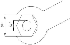
General Torque
| Nut (a) | Bolt (b) | |
|---|---|---|
| 8mm | M5 | 5Nm |
| 10mm | M6 | 8Nm |
| 12mm | M8 | 18 Nm |
| 14mm | M10 | 36Nm |
| 17mm | M12 | 43Nm |
Periodic Service
Maintenance Time Table
| Items | Contents | Initial maintenace | Initial maintenace | General maintenance period | General maintenance period |
|---|---|---|---|---|---|
| Items | Contents | 10 hours (month) | 50hours (3 months) | 100hours (6 months) | 200 hours (1 year) |
| Anode | Inspection/replacement | O | O | ||
| Spark plug | Cleaning/ adjustment /replacement | O | O | ||
| Grease points | Greasing | O | |||
| Bolts and nuts | Inspection | O | O | ||
| Fuel filter | Inspection/replacement | O | O | O | |
| Fuel tank | Inspection/ cleaning | O | |||
| Throttle cable | Inspection/adjustment/ replacement | O | O | ||
| Idling speed | Inspection/adjustment | O | O | ||
| Start-in-gear projection | Inspection/ adjustment | O | O | ||
| Engine oil | Replacement | O | O | ||
| Oil filter | Replacement | O | |||
| Valve clearance (OHC) | Inspection/ adjustment | O | O | ||
| Ignition timing | Inspection | O | O | ||
| Thermostat | Inspection | O | |||
| Cooling water passage | Inspection/Cleaning | O | O | ||
| Gear oil | Replacement | O | |||
| Water pump | Inspection | O | |||
| Propeller | Inspection/replacement | O | O | ||
| Timing belt | Inspection/replacement | O | O |
CAUTION:
After running the outboard engine in salt water,waste water or mudwater,wash over the enginebyfreshwaterimmediately.
If using leaded gasoline frequently, check the valve and components each 100 hours. Timing belt should be changed every 1000 hours (5years).
Fuel System
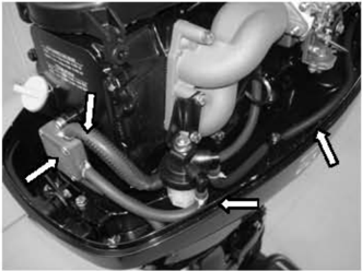
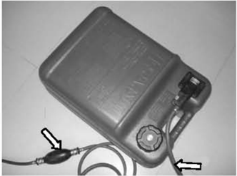
- CHECKFUELTANK,CARBURETOR,FUELPUMPANDFUELPIPE Check if fuel tank, carburetor, fuel pump and fuel pipe are damaged or leaked. Replace if necessary. Check if the fuel filter on the tank is dirty.Clean dirt or replace if necessary.
- 2.CHECKFUELCOCKANDFUELJOINT Check if fuel cock and fuel joint are cracked, damaged or leaking. Replace if necessary.
- CHECKFUELFILTER Check if fuel filter is cracked, damaged or has dirt inside. If so, replace.
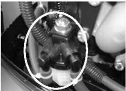
CAUTION: Clean the spilled fuel.
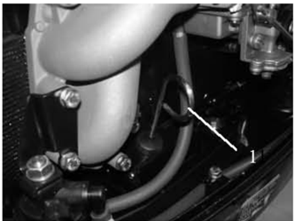
Power Unit
Engine Oil Level
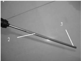
- 1.Remove oil rule, check engine oil level,ifbetween the following marks of the upper and lower.
1.Oil rule
2.High position mark
- Low position mark
- 2.If above the upper mark, drain the engine oil; if below lower mark, add engine oil up to upper mark. CAUTION:
Run the engine and then turn it off, wait for several minutes, and check the engine oil level by the oil rule again.
If the engine oil still not within the proper level, add/drain as needed.
Changing Engine Oil
- 1.Remove oil level plug, drain plug with washer and gasket; drain off the engine oil.
- Install new bolt and washer; install drain plug.
- 3.Fill engine oil through oil filler hole.
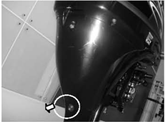
Engine oil quantity: 1.0 L (Before changing oil filter)
1.2 L (After changing oil filter)
APISE,SF,SE-SF,SG-CDSAE10W30,10W40
Oil type:
- Install oil level plug.
- Check engine oil level.
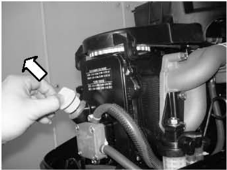
Valve Clearance
- 1.Remove stopper hang rope from engine stop switch assy. Remove spark plug cap from spark plug.
- 2.Remove starter and belt cover.
- 3.Remove fuel pump and cylinder cover.
- Rotate the flywheel clockwise to make the mark "1" on driven pulley align with the mark """ on the cylinder head.
Check the clearance between the intake and exhaust valves of the upper cylinder. Adjust it if necessary.
- uo the cylinder head.
Check the clearance between the intake and exhaust valves under the lower cylinder.Adjust it if necessary.
CAUTION:
Don't rotate the flywheel counter clockwise in case the valve system is damaged.
NOTE:
Adjust the valve clearance when the engine is cold.
| Valve clearance | Intake valve | 0.15~0.25mm |
|---|---|---|
| (cold position) | Exhaust valve | 0.20~0.30mm |
- Loose lock nut, rotate adjusting bolt to reach the specified valve clearance.
NOTE:
Rotate adjusting bolt clockwise toreduce thevalve clearance.
Rotate adjusting bolt counter clockwise toincrease thevalve clearance.
- 7.Re-assemble the spare parts.
Recoil start type:
- Turn the throttle grip to fully closed position.
- Check if the throttle cable is slack, if the throttle lever touches the throttle stop screw, or if the arresting stop on the throttle accelerograph enforce touches the check plate on the fixed mount.
- 3.Loosen the throttle cable adjusting screw, adjust the throttle cable position, and tighten throttle cable adjusting screw.
Spark Plug
- Remove spark plug cap and spark plug.
- Clean off carbon build-up on the electrodes.
- Check if the electrodes are corroded or have deposit, or if the washer is damaged. If necessary, change the spark plug. Spark plug type: DPR7HS
- Inspect if the spark plug gap is within specification. If necessary, change the spark plug.
- Install spark plug. Use spark plug spanner to tighten it according to specified torque. Specified torque: 18 Nm
Control System
Throttle Grip
1.throttle cable stop screw
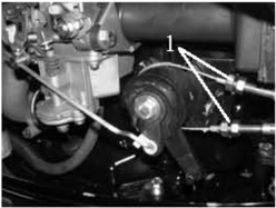
Electric start type:
- Turn the gear shift lever to neutral position.
- Check if the arresting stop on the throttle accelerograph enforce touches the check plate on the bracket.
- check plate 2. arresting stop
- 3.Loosen the lock nut and take out the cotter pin, then remove the cable joint.
- 4.Adjust the joint position to make the joint hole align with the pin on the throttle accelerograph enforce.
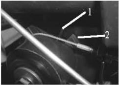
- cotter pin 2. cable joint 3. lock nut
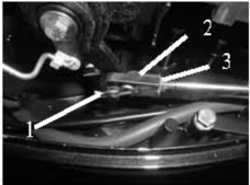
CAUTION:
The cable jointmust be screwed in for over 8mm.
- 5.Fit on the cotter pin and tighten the lock nut.
Idling Speed
Check iding speed, and adjust it if necessary.
- 1.Preheat engine for 5 minutes.
- Attach the tachometer to the spark plug wire to measure idling speed RPM.If out of specification, adjust it.
Idling speed:
900~1000r/min
- 3.Turn the throttle stop screw clockwise or counter clockwise, until the specified idling speed is attained.
NOTE:
Turn clockwise to increase idling speed. Turn counter clockwise to decrease idling speed. If necessary, turn the idling speed screw on the carburetor clockwise or counter clockwise, until the specified idling speed is attained.
CAUTION:
Before adjusting the idling speed, the throttle cable should beproperly adjusted. After adjusting the idling speed, if necessary, you can adjust the throttle cable again.
Start-in-Gear Protection
Set the shift lever in neutral, and check if the tightwire end of the arrester aligns with the marking of the align with the marking.
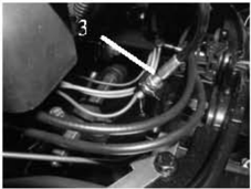
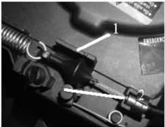
- “" marking 2. tightwire assy, arrester 3. adjusting nut
Lower Unit
Gear Oil
Check Gear Oil Level
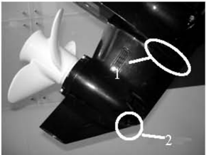
Remove the oil level plug screw. If the gear oil overflows, the oil level is correct; otherwise, add gear oil.
- Oil level plug screw
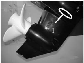
Changing Gear Oil
- 1 Hold the outboard engine in an upright position.
- Place a container with enough capacity under the outboard engine.
1.throttle stop screw 2. idling speed screw
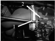
- Remove the drain plug screw, the oil level plug screw, and then drain the gear oil.
- 1.Oillevel plug screw2.Drain plug screw
- Add gear oil through the drain plug hole using pressure filing device.
- 5 When gear oil overflows through the oil level plug hole, install the oil level plug screw.
- Install the drain plug screw, then clean overflowing gear oil. NOTE:
Check the drained gear oil. If the gear oil is milky, check the oil seal.Replace the oil seal if necessary. _ If the gear oil contains metal chippings, check the gear and bearing.
CAUTION:
Must change drain plug washer each time.
Lower Unit Leakage Check
Connecting the leakage tester to the oil level plug hole to check for the lower unit leakage.If the
General Inspection
Anode
Inspect lower unit anode and engine anode (on the thermostat cover).Clean the greasy dirt and scales. If wear or damage is above 1/2, replace the anode.
CAUTION:
Cannot grease or paint the anode, or it will not operate properly.
Grease Points
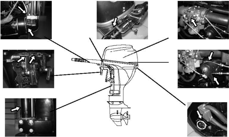
- 1.Refer the illustration for greasing points, paint the water resistant grease.
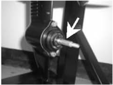
- 2.Paint anti-corrosion grease on the propeller shaft.
Cooling Water Passage
- 1.Inspect cooling water passage, if blocked, clean it.
- 2.Place the outboard engine in the water and ensure the water level is above the anti-vortex plate, then start the engine.
- 3.Check if water overflows at the cooling water checking hole.If there is no flow or intermittent flow,checkthecoolingwaterpassage.
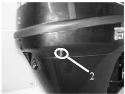
- Cooling water passage inlet
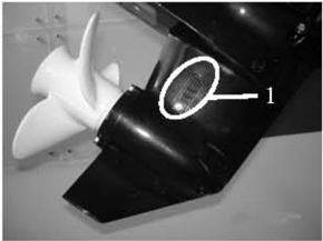
- Cooling water inlet
2.Coolingwatercheckinghole
Thermostat
- 1.Remove the thermostat cover and thermostat.
- Hangthethermostatin a containerwithwater.
- 3.Heat the container.
- Check the valve open height under the specified water temperatures. If out of order, change it.
- 5.Fit on the thermostat and thermostat cover, then tighten the screws to specification.
| Watertemperature | Valve open height |
|---|---|
| Under 62°C | 0.1mm |
| Over 70°℃ | Over 3mm |
Recoil Starter
NOTICE:
When you service, always wear safety glasses and gloves. To prevent accidental start of the engine, remove the spark plug cap and remove stopper hang rope from stop switch assembly.
Explosive Drawing
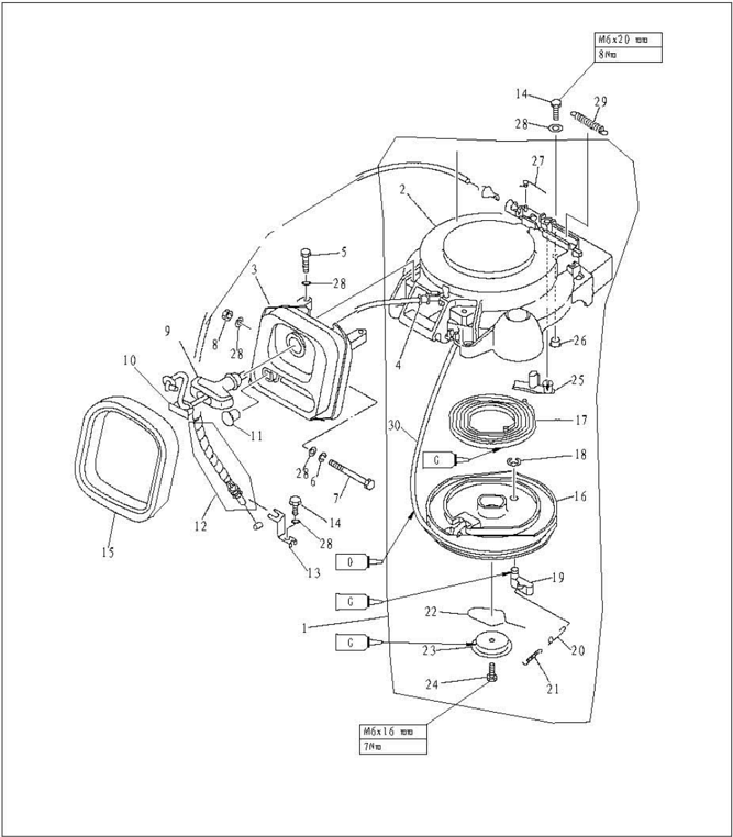
| SH. | PART NO. | DESCRIPTI0N | QTY | REMARKS | |
|---|---|---|---|---|---|
| 1 | F15-07130000 | STARTER ASSY | 1 | ||
| 2 | F15-07130101 | CASE,STARTER | 1 | ||
| 3 | F15-07130300 | FRAME,STARTER | 1 | ||
| 4 | F4-04130013 | COLLAR | 1 | ||
| 5 | CB/T5783-M6x25 | M6x25 | BOLT M6x25 | 2 | |
| 6 | CB/T93-6 | 6 | WASHER,SPRING | 1 | |
| 7 | CB/T5782-M6x99M6x90 | BOLT M6x90 | 1 | ||
| 8 | CB/T6170-M6 | M6 | NUTM6 | 1 | |
| 9 | F4-04130101 | HANDLE, STARTER | 1 | ||
| 10 | F4-04130102 | COVER | 1 |
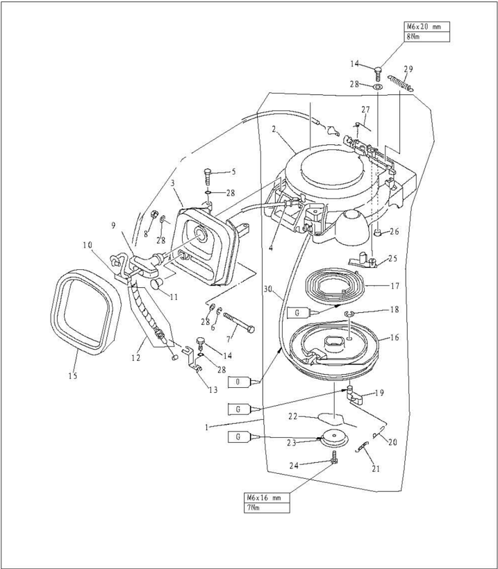
| SN. | PART NO. | DESCRIPTION | DESCRIPTION | QTY | REMARKS |
|---|---|---|---|---|---|
| 11 | F15-07130305 | GROMMET | 1 | ||
| 12 | F15-05000028 | ARRESTER TIGHTWIRE ASSY | 1 | ||
| 13 | F15-05000027 | FRAME,ARRESTER TIGHTWJRE | 1 | ||
| 14 | GB/T5783-M6x20M6x20 | BOLT M6x20 | 3 | ||
| 15 | F15-07130304 | SEAL,FROTHY RUBBER | 1 | ||
| 16 | F15-07130201 | WHEEL,START-UP | 1 | ||
| 17 | F15-07130107 | SPRING,VOLUTE | 1 | ||
| 18 | GB/T896-8 | 8 | CIRCLIP8 | 1 | |
| 19 | F15-07130202 | PAWL,DRIVE | 1 | ||
| 20 | F15-07130204 | LINK,PAWL | 1 |
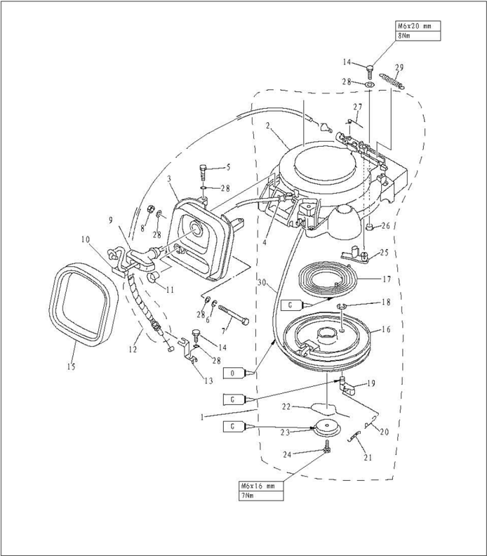
| SN. | PART NO. | DESCRIPTION | QTY | REMARKS | |
|---|---|---|---|---|---|
| 21 | F15-07130203 | SPRING,TENSION | 1 | ||
| 22 | F15-07130002 | SPRING,DRIVE PLATE | 1 | ||
| 23 | F15-07130001 | PLATE,DRIDE | 1 | ||
| 24 | CB/T5783-M6x16 | M6x16 | BOLTM6x16 | 1 | |
| 25 | F15-07130105 | ARRESTER | 1 | ||
| 26 | F15-07130102 | BUSH,SHOULDER | 3 | ||
| 27 | F15-07130106 | SPRING,ARRESTER | 1 | ||
| 28 | CB/T97.1-6 | 6 | WASHER PLATE | 8 | |
| 29 | F15-05000029 | TICHTWIRE,SPRING | 1 | ||
| 30 | F15-07130205 | Φ4x1.78STARTLINC | Φ4x1.78STARTLINC | 1 |
Electric start type:
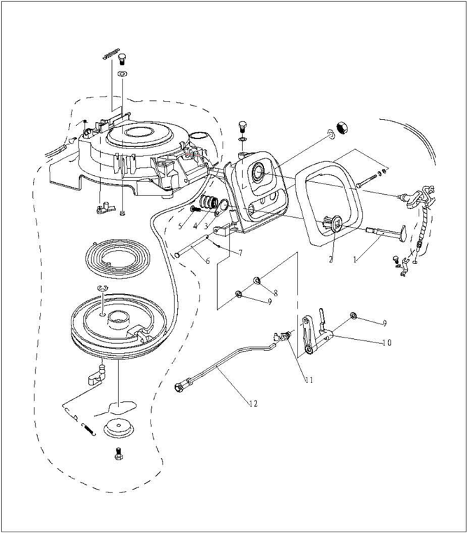
| SN. | PART NO. DESCRIPTION | Q7 | REMARKS | |
|---|---|---|---|---|
| 1 | F15-07130306WB | HANDLE"B" | 1 | |
| 2 | F15-05010001 | BUSH | 1 | |
| 3 | F15-07130308W | PLATE | 1 | |
| 4 | F15-07130307WB | BUSH,WAVE | 1 | |
| 5 | CB/T845-85 | ST4.8X9SCREWPANREAD ST4.8x9 | 1 | |
| 6 | F15-07130310W | SHAFTROCKER | 1 | |
| 7 | GB/T91-1.6x121.6×12 | COTTER PIN 1.6x12 | 1 | |
| 8 | F15-07130312W5 | WASHER,SPRING SADDLE | 1 | |
| 9 | F15-07130311W5 | WASHER,NYLON | 2 | |
| 10 | F15-07130309W | ROCKER | 1 | |
| 11 | F15-07130314W | TIE-IN | 1 | |
| 12 | F15-07130313 | LINK RODASSY | 1 |
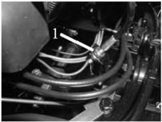
- Open the top cowling.
- Screw loosely the adjusting nut of the arrester tightwire.
- 3.Remove the tightwire from the arrester.
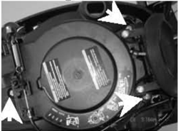
- 4.Remove the starterfixingbolts,and remove the starter.
- Adjusting nut
Starter Rope Replacement
- 1.Pull the starter rope out, and insert it in the notch of the start-up wheel. Turn the start-up clockwise until the volute spring is free.
- 2.Pull the starter rope out completely.
- 3.Remove the starter handle cover from the starter handle, and remove the starter rope. Untie the knot at the end of the starter rope.
- 4.Pull out the starter rope from the start-up wheel completely.
- 5.Insert the new starter rope into the starter, and fix the starter rope onto the start-up wheel and starter handle.At the end of the rope tie a knot as shown.
Disassembling
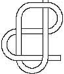
- 6.Insert the start rope in the notch of the start-up wheel and turn the start-up wheel several rounds in counterclockwisedirection.
- Pull the starter handle many times to check if the start-up wheel rotates stably. If necessary, repeat step 6 and step 7.
Disassembling and Inspection
Recoil start type:
- Remove the start rope and start frame assy.
- Remove drive plate screw, and remove the drive plate and drive plate spring.
- Remove the start-up wheel.
WARNING:
Uninstall the start-up wheel carefully, to ensure that the volute spring does not pop out to hurt people.
- Remove the volute spring.
- Remove the arrester and arrester spring.
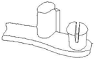
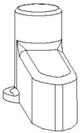
- Inspect if the arrester is cracked, worn or damaged. Replace if necessary.
- Inspect if the drive pawl is cracked, worn or damaged. Replace if necessary.
- Check if the tension spring and pawl link are cracked, cranked or damaged. Replace if necessary.
- Check if the volute spring is broken, cranked or damaged. Replace if necessary.
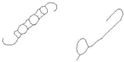
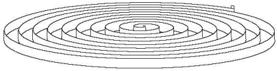
Electric start type:
- 1.Remove the link rod assy of chock valve.
- Remove the cotter pin and rocker shaft.
- Remove the rocker.
- 4.Remove the bush plate, guide bush and chock valve handle.
- Check if the link rod assy is cranked or deformed. Replace if necessary.
- Check if the chock valve rocker and handle are cracked or damaged.Replace if necessary.
Assembling
Reverse the steps of disassembling starter.
Installation
- 1.Put starter onto the power unit.
- Screw the hexagon bolt, and tighten it according to the specified torque.
- Install the arrester tightwire.
- Adjust the adjusting nut on the tightwire of the arrester, and align the arrester tightwire end with the marking of the starter case.

marking 2. Arrester tightwire 3.Adjusting nut
Ignition System
NOTICE:
When checking and repairing the ignition system, keep your hand, clothes, hair or personal belongings away from the rotatingflywheel.
Check ignition coil on insulated working table, to prevent electricity leak and electroshock.
Don't touch the ignition coil or spark plug when the engine is running, to avoid electroshock. Keep the wires away from the rotating flywheel, to prevent the wire from being cut, or the insulating layer of the wire from being worn.
When replacing fixing parts such as nuts and bolts, only parts from original manufacturer or parts made of same material and with strength can be used.Parts must be tightened according to the specified torques.
Explosive Drawing
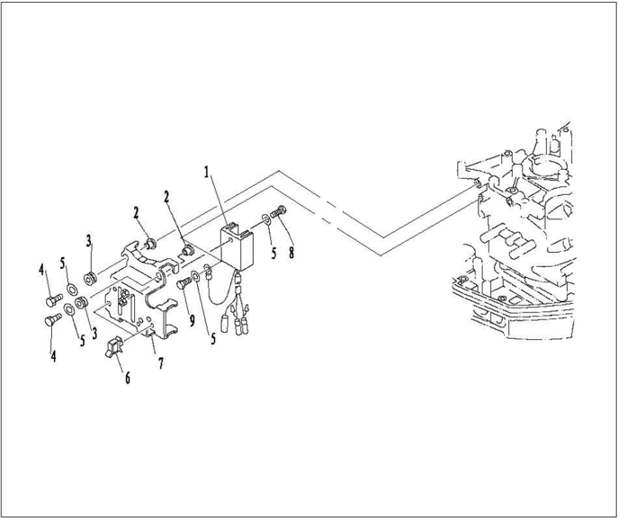
| SN. | PART NO. | DESCRIPTION | QTY | REMARKS | |
|---|---|---|---|---|---|
| 1 | F15-07060001 | RBCTIFIER®ULATORASSY | 1 | ||
| 2 | F15-07060004 | LINER | 4 | ||
| 3 | F15-07060003 | GASKET,SHOCK ABSORPTION | 4 | ||
| 4 | GB/T5783-M6x25 | M6×25 | HEXAGON BOLT M6×25 | 4 | |
| 5 | GB/T97.1-6 | 6 | VASBER | 6 | |
| 6 | F15-07060005 | B | QUADRATE CLAMP | 2 | |
| 7 | F15-07060002 | BRACKET,RICTIFIER | 1 | ||
| 8 | GB/T5783-M6x16 | M6x16 | BBXAGON BOLT M6×16 | 1 | |
| 9 | GB/T5783-M6x16 | M6×12 | BEXAGONBOLT M6×12 | 1 |
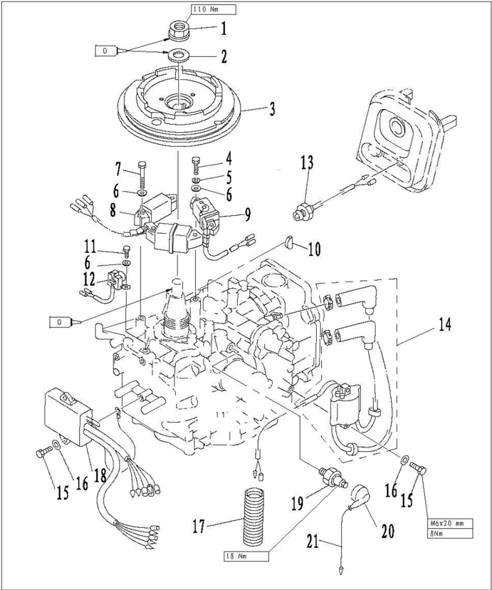
| SN. | PART NO. | DESCRIPTION | QTY | REMARKS | |
|---|---|---|---|---|---|
| 1 | F15-07000006 | NUT,FLYWHEEL | 1 | ||
| 2 | F15-07000005 | VASHERFLYWBEEL NUT | 1 | ||
| 3 | F15-07070000 | FLYWHEBL ASSY | 1 | ||
| 4 | GB/T5783-M6x25 | M6×25 | HEXAGON BOLT M6×25 | 2 | |
| 5 | GB93-6 | 6 | WASHERSPRING | 2 | |
| 6 | GB/T97.1-6 | 6 | WASHER | 8 | |
| 7 | GB/T5783-M6x30 | M6×30 | HEXAGON BOLT M6×30 | 4 | |
| 8 | F15-07000400 | A、B | COIL,CHARGE"AB"ASSY | 1 | |
| 9 | F4-07000300 | COIL | 1 | ||
| 10 | F15-0700004 | EYSEMISIRCLE FLYEBL | 1 | ||
| 11 | GB/T5783-M6x16 | M6x16 | HEXAGON BOLT M6×16 | 2 | |
| 12 | F15-07000200 | COIL,PULSER | 1 |
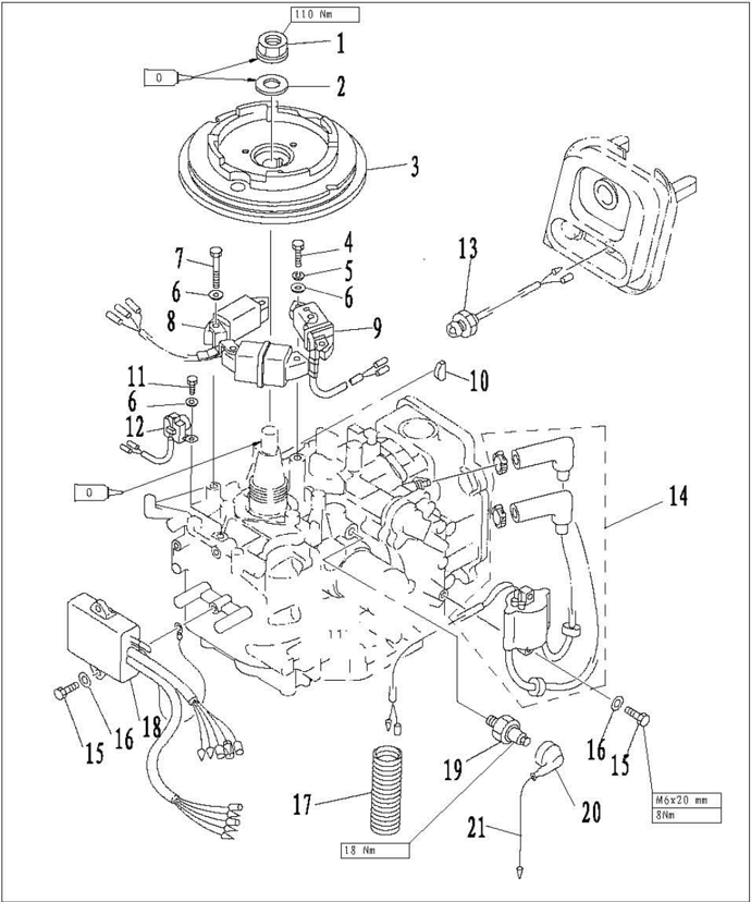
| 8N. | PART NO. | DESCRIPTION | QTY | REMARKS |
|---|---|---|---|---|
| 13 | F15-07130303 | EMERGENCY SIGNAL LIGBT ASSY 1 | ||
| 14 | F15-07000600 | HIGE PRESSURB ASSY 1 | ||
| 15 | GB/T5783-M6x20 | M6×20 | HEXACON BOLT M6×20 4 | |
| 16 | GB/T97.1-6 | 6 | WASHER 4 | |
| 17 | F15-07000003 | Φ27×22.5×71 | RIPPLE TUBE | |
| 18 | F15-07000500 | C.D.I. UNIT ASSY 1 | ||
| 19 | F15-07010103 | OIL PRESSURE SENSOR 1 | ||
| 20 | F15-07010101 | JACKET,INSJULATION 1 | ||
| 21 | F15-07010102 | LEAD WIRE ASSY 1 |
Electric start type:
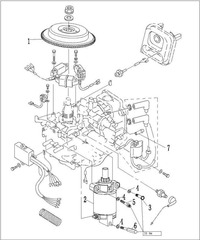
| SN. | PART NO. | DESCRIPTION | QTY | REMARKS |
|---|---|---|---|---|
| 1 | F15-07070100W | FLYWHEEL ASSY 1 | ||
| 2 | F15-07150100W | STARTUP HOTOR 1 | ||
| 3 | GB/T5782-M8x50 | M8x50 | HEXAGON BOLT M8x50 1 | |
| 4 | GB/T97.1-8 | 8 | WASHBR8 3 | |
| S | F25-05170001W | M8 | FIXATION BOLT,MOTOR 1 | |
| 6 | F15-07150002W | M8 | COLUMMAR BOLT 1 | |
| 7 | F25-05010402W | VATER GAP 1 |
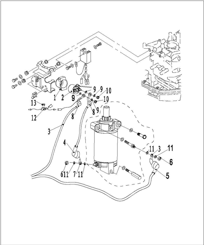
| SN. | PART NO. | DESCRIPTION | QTY | REMARKS |
|---|---|---|---|---|
| 1 | F15-07150301W | RELAY JACKET 1 | ||
| 2 | F15-07150300W | RELAY 1 | ||
| 3 | F15-07150200W | LINE,POWER SOURCE 1 | ||
| 4 | F25-05170201W | COVERINGAPOWE SOURCB LINE 1 | ||
| 5 | F25-05170202V | B | COVERING B,POWER SOURCE LINE 1 | |
| 6 | GB/T6170-M8 | M8 | HEXANGULAR NUT M8 2 | |
| 7 | F15-07150500V | CONNECTION LINE,MOTOR 1 | ||
| 8 | F15-07150501V | JACKET,CONECTIONLINE 2 | ||
| 9 | GB/T97.1-6 | 6 | WASHER6 4 | |
| 10 | GB/T6170-J6 | M6 | HEXANGULAR NUT M6 2 | HSn62-1 |
| 11 | CB/T97.1-8 | 8 | VASHER8 | 4 |
| 12 | F25-05090100W | JEF-709JFUSEASSY 1 | ||
| 13 | F15-07150001V | 20A | FUSE 1 |
Wire beam color:
Wiring Diagram
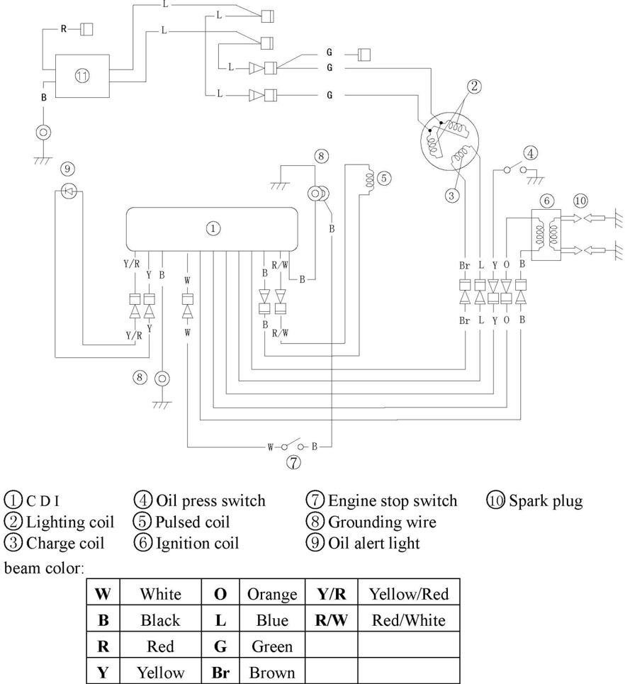
| W | White | 0 | Orange | Y/R | Yellow/Red |
|---|---|---|---|---|---|
| B | Black | L | Blue | R/W | Red/White |
| R | Red | G | Green | ||
| Y | Yellow | Br | Brown |
Spark Plug Ignition
- Remove spark plug cap from spark plug.
- Connect the ignition tester to the spark plug cap.
- Start the engine, and observe the sparks through the discharge window of the tester.
WARNING:
Do not touch any joint part of the lead wire of the tester. Keep away from inflammable gas or liquid, to prevent accident resulting from spark ignition.
CDI Peak Voltage
Use the digital circuit tester and peak voltage adaptor to measure CDI peak voltage.Ifbelow the specification, check the lead wire and measure the impulse and peak voltage output of the charge coil.
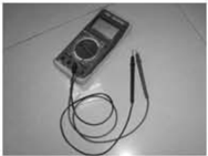
Digital circuit tester
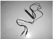
Peak voltage adaptor
| CDI peak voltage output | Start (load) | 155V |
|---|---|---|
| CDI peak voltage output | 1500r/min | 170 V |
| CDI peak voltage output | 3500r/min | 170V |
If the impulse and peak voltage output of the charge coil are just same as or above the specification, and the CDI peak voltage output is below the specification,replace the CDI.
Ignition Coil Inspection
- Remove the ignition coil and spark plug cap.
- Measure ignition coil resistance.Replace if out of the specification.
Resistance:0.16~0.25Q
(Tester (+) pole: orange wire; Tester (-) pole: black wire)
3.92~6.65kΩ
(Tester (+) pole: orange wire; Tester (-) pole: high-voltage wire)
NOTE:
Spark Plug Cap
- Remove the spark plug cap.Check if the spark plug cap is broken. Replace if necessary.
- Install the spark plug cap. Turn it clockwise until it is tight.
Flywheel Maintenance
- 1.Use flywheel gripper to remove the nut and starter bush; use flywheel puller to remove flywheel.
- 2.Check if the flywheel is damaged or the permanent magnet part is firm.Replace if necessary.

CDI Inspection
- 1.Pulsed coil peak voltage
Use the digital circuit tester and peak voltage adaptor to measure the peak voltage.If below the specification, check the pulsed coil resistance.
Digital circuit tester
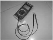
Pulsed coil peak voltage
- 2.Pulsed coil resistance
Measure the pulsed coil resistance.Replace if out of specification, replace.
Resistance: 234~348 Q (Tester (+) pole: red/white wire; Tester (-) pole: black wire)
Charge Coil Inspection
- 1.Charge coil peak voltage
Use the digital circuit tester and peak voltage adaptor to measure the peak voltage.If below the specification, check the charge coil resistance.
Digital circuit tester
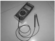
Charge coil peak voltage
- 2.Charge coil resistance
Measure charge coil resistance.Replace if out of specification.
Resistance: 272 ~408 Q (Tester (+) pole: brown wire; Tester (-) pole: blue wire)
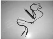
Peak voltage adaptor
| Start (no-load) | 175V |
|---|---|
| Start (load) | 170V |
| 1500rmp | 180V |
| 3500rmp | 180V |
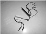
Peak voltage adaptor
| Start (no-load) | 4.0 |
|---|---|
| Start (load) | 4.0 |
| 1500r/min (load) | 9 |
| 3500r/min (load) | 17V |
Pulsed Coil Inspection
Fuel System (Detailed)
NOTICE:
Gasoline is inflammable and highly volatile liquid. Its leakage can cause fire and explosion. Don't start the engine before all joints of the fuel system are connected or installed. When completing all maintenance steps, force short-time pressure to the fuel system to check for leakage.
Explosive Drawing
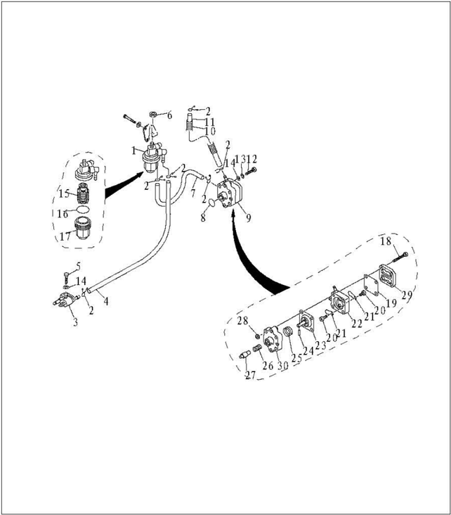
| SN. | PART NO. | DESCRIPTION | QTY | REMARKS |
|---|---|---|---|---|
| 1 | F15-07080000 | FILTER ASSY | 1 | |
| 2 | F4-04000030 | B SPRING,FUELPIPEB" | 6 | |
| 3 | F4-05000200 | FUELPIPETIE-INASSY | 1 | |
| 4 | F15-05000016 | A010x5x505 PIPE,FUEL A | 1 | |
| 5 | GB/T5783-M6x2dM6x20 BOLT M6x20 | 1 | ||
| 6 | GB/T6170-M8 | M8 NUT M8 | 1 | |
| 7 | F15-07000027 | HOSE(IN) | 1 | |
| 8 | JAS0F44/A-24-021 | 0 O-RING | 1 | |
| 9 | F15-07140000 | FUEL,PUMP ASSY | 1 | |
| 10 | F15-07000026 | 1 | ||
| 11 | F15-07000025 | JACKET HOSE(OUT) | 1 | |
| 12 | GB/T823-M6x30+M6x30 SCREW,SMALLPANREADM6x30 | 2 |
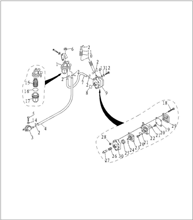
| SN. | PART NO. | DESCRIPTION | DESCRIPTION | QTY | REMARKS |
|---|---|---|---|---|---|
| 13 | GB/T93-6 | 6 | WASHER,SPRING6 | 2 | |
| 14 | GB/T97.1-6 | 6 | WASHER,PLATE 6 | 3 | |
| 15 | F15-07080001 | ELEMENT,FILTER | 1 | ||
| 16 | GB/T3452,1-32.5x1.8 | 32.5x1.8WASHERCUPFILTER | 32.5x1.8WASHERCUPFILTER | 1 | |
| 17 | F15-07080002 | CUP,FILTER | 1 | ||
| 18 | GB/T818-M4x30 | M4x30 SCRRWPANHEADM4x30 | M4x30 SCRRWPANHEADM4x30 | 4 | |
| 19 | F4-04090004 | DIAPHRAGM,TOP | 1 | ||
| 20 | F4-04090011 | M3x5 | SCRRW,VALVEM3x5 | 2 | |
| 21 | F4-04090005 | PLATE | 2 | ||
| 22 | F15-07140002 | FUEL PUMP SHELL | 1 | ||
| 23 | F15-07140100 | DIAP HRAGM ASSY | 1 | ||
| 24 | GB/T309-3x12 | 3x12 | ROLLER NEEDLE | 1 |
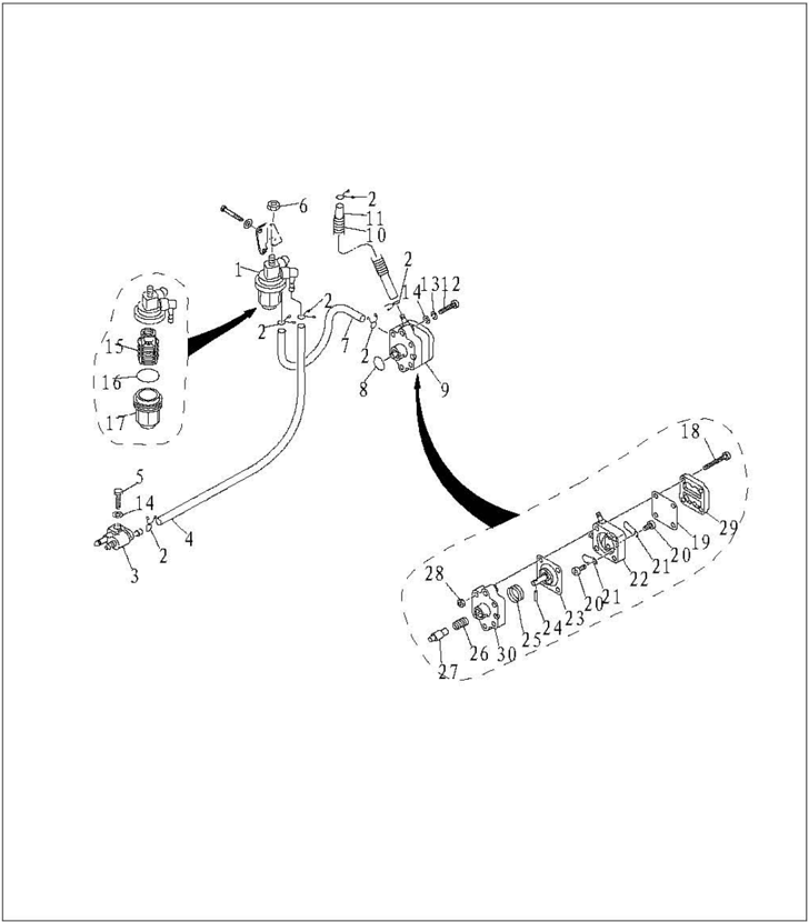
| SN. | PART NO. | DESCRIPTION | DESCRIPTION | QTY | REMARKS |
|---|---|---|---|---|---|
| 25 | F15-07140005 | SPRING,DIAP HRAGEM | 1 | ||
| 26 | F15-07140004 | SPRING,PLUNGER | 1 | ||
| 27 | F15-07140003 | PLUNGER | 1 | ||
| 28 | GB/T6170-20000 | NUTM4 | 4 | ||
| 29 | F4-04090003 | COVER,FUEL PUMP | 1 | ||
| 30 | F15-07140001 | SEAT,FUEL PUMP | 1 |
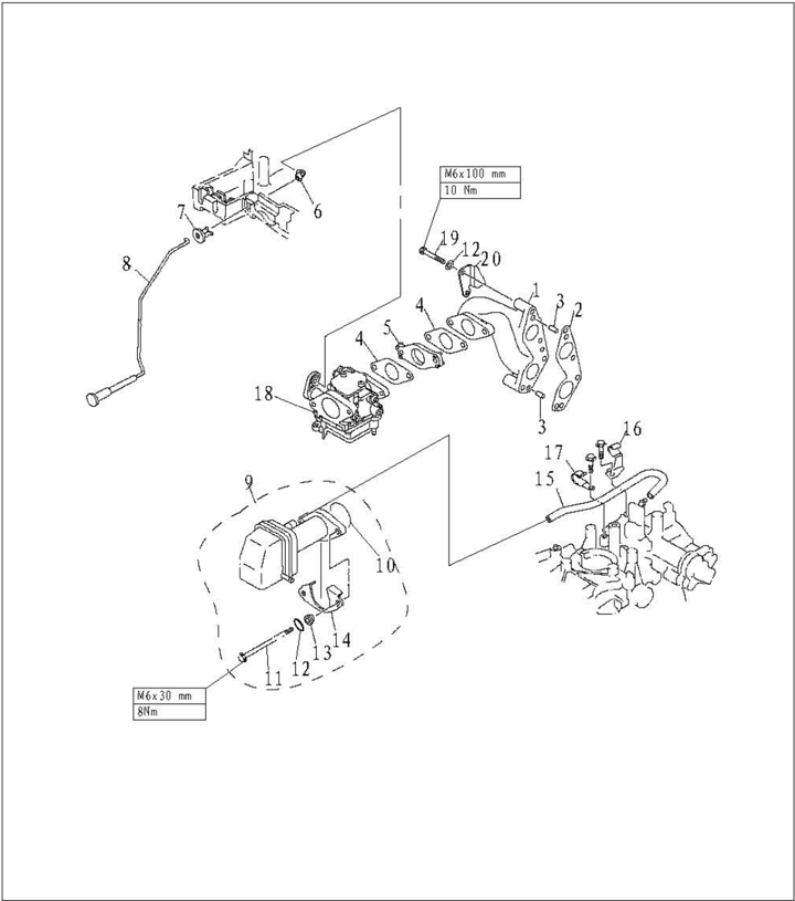
| SN. | PART NO. | DESCRIPTION | QTY | REMARKS |
|---|---|---|---|---|
| 1 | F15-07000008 | MANIFOLD,INTAKE | 1 | |
| 2 | F15-07000007 | GASKETMANIFOLD | 1 | |
| 3 | F15-00000006 | 6x12 PIN,D0WEL6x12 | 2 | |
| 4 | F15-07000017 | GASKET,CARBURETOR | 2 | |
| 5 | F15-07000018 | INSULATOR,CARBURETOR | 1 | |
| 6 | F15-05010003 | JOINT,CHOKE LEVER | 1 | |
| 7 | F15-05010001 | CASE,STARTER | 1 | |
| 8 | F15-05010100 | ROD,CHOKE | 1 | |
| 9 | F15-07100000 | SILENCER ASSY,INTAKE | 1 | |
| 10 | GB34521-35.5x1.8 | 035.5x1.8 0-RING 35.5x1.8 | 1 | |
| 11 | GB/T5782-M6x100 | M6x100 HEXAG0N B0LT M6x100 | 2 | |
| 12 | GB/T97.1-6 | 6 WASHER,PLATE 6 | 6 |
| SN. | PART NO. | DESCRIPTION | QTY | REMARKS |
|---|---|---|---|---|
| 13 | F15-07000021 | BUSHER,INTAKE SILENCER | 2 | |
| 14 | F15-07000022 | PLATE,INTAKESILENCER | 1 | |
| 15 | F15-07010017 | PIPE,BREATHER | 1 | |
| 16 | F15-07010016 | B CLAMPB | 1 | |
| 17 | F15-07010015 | A CLAMPA | 1 | |
| 18 | F15-07090000 | CARBURETOR | 1 | |
| 19 | GB/T5783-M6x40 | M6×40 BOLT M6×40 | 4 | |
| 20 | F15-07000009 | BRACKET,OILSIEVE | 1 |
Electric start type:
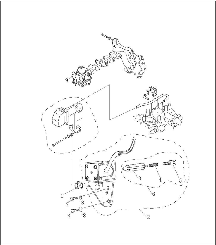
| SN. | PART NO. | DESCRIPTION | QTY | REMARKS | |
|---|---|---|---|---|---|
| 1 | F4-02000011 | SEAL,SHAFT | 1 | ||
| 2 | F15-11030000W | ELECTROMAGNBTIC MAGNETASSY | 1 | ||
| 3 | F15-11030301W | IRON CORE | 1 | ||
| 4 | F15-11030302W | LINK RAD,IRON CORE | 1 | ||
| 5 | F15-11030303W | HOOK,IRON CORE | 1 | ||
| 6 | F15-11030300W | IRON CORE ASSY | 1 | ||
| 7 | GB/T5783-M6x12 | M6X12 | BOLT,HEXAG0N M6x12 | 2 | |
| 8 | GB/T97.1-6 | 6 | WASHER6 | 2 | |
| 9 | F15-07090000 | CARBURETOR | 1 |
Throttle Connecting Rod Adjustment
- Turn throttle accelerograph enforce to full opening position. Turn carburetor throttle rod to full opening position.
- 1.Throttle accelerograh enforce
- 2.Carburetor throttle rod
- 3.Lock screw
- In full opening position, tighten the throttle rod lock screw.
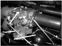
Fuel Joint Removal and Inspection
- 1.Remove the bolts fixing the fuel joint.
- 2.Remove the fuel joint.
- Inspect the fuel joint for crack or damage.
- 4.Connect the fuel joint exit with a vacuum pressure gauge.
- Check whether the negative pressure can be maintained for over 10 minutes under the prescribed pressure. Replace if necessary. Prescribed pressure: 50kPa.

Fuel Pump Removal and Inspection
- Remove the bolts fixing the fuel pump.
- 2.Remove the fuel pump.
- Connect the fuel pump intake with a vacuum pressure gauge.
- Block the exit of fuel pump with finger, and force a prescribed positive pressure to check for leakage.
- Force a prescribed negative pressure and check for leakage. Prescribed pressure: 50kPa
- Connect the fuel pump exit with a vacuum pressure gauge.
Prescribed pressure: 50kPa
- Force a prescribed negative pressure and check for leakage.Disassemble the fuel pump to check if necessary.
- 8.Remove four bolts, and separate fuel pump cover from fuel pump seat.
- Remove the valve screw from fuel pump, and remove the valve plate.
- Press the plunger and diaphragm, rotate the fuel pump seat, and align the notch with the notch on the plunger. Take the roller needle out.
- Inspect the diaphragm for crack and valve for damage. Replace if necessary.
- Reverse above step 8 to step 10 to install the fuel pump.
Prescribed pressure:50kPa
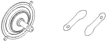
Filter Inspection
Check if the filter element is clogged or with foreign matter.Check the filter cup for damage or leakage. Use gasoline to clean it, or replace if necessary.
NOTE:
Coat a layer of gasoline onto the O-ring before installing the filter cup.


- 1.Filter cup
- O-ring
- 3.Filterelement
- 4.Filter cap
Power Unit (Detailed)
NOTICE:
To avoid accidental start of outboard engine during maintenance, please take enough safety measures to disconnect the ignition system.For instance, remove the engine stop lanyard from engine stop switch assembly,and remove spark plugcapfrom spark plug.
Explosive Drawing
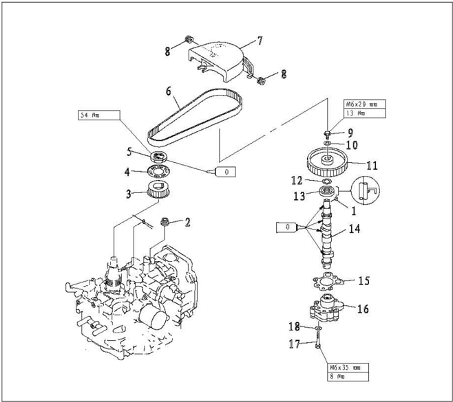
| 8H. | PART NO. | DESCRIPTI0N | QTY | REMARKS |
|---|---|---|---|---|
| 1 | GB/T1099-1979 | KEY,WOODRUFF | 1 | |
| 2 | F15-07010027 | B | RUBBER RING B | |
| 3 | F15-07030003 | BELT PULLEY,TIMING | BELT PULLEY,TIMING | |
| 4 | F15-07030004 | WASHER | 1 | |
| 5 | F15-07030005 | NUT | 1 | |
| 6 | F15-07000002 | BELT,TIMING | 1 | |
| 7 | F15-07000024 | COVER,DUST | 1 | |
| 8 | F15-07050003 | A | RING RUBBER A | 2 |
| 9 | GB/T5783-M6x16 | M6x16 | BOLT M6x16 | 1 |
| 10 | GB/T5287-6 | 6 | BIG WASHER6 | 1 |
| 11 | F15-07040018 | BELT PULLEY,DRIVEN | BELT PULLEY,DRIVEN | |
| 12 | F15-07040017 | WASHER | 1 | |
| 13 | F15-07040008 | 18X35X7-R | OIL SEAL 18X35X7-R | 1 |
| 14 | F15-07040200 | CAMSHAFT ASSY | 2 | |
| 15 | F15-07040016 | MAT,QIRPROOF | 4 | |
| 16 | F15-07040500 | OIL PUMP ASSY | 1 | |
| 17 | GB/T5783-M6x35 | M6x35 | BOLTM6x35 | 3 |
| 18 | GB/T97.1-6 | 6 | WASHER6 | 3 |
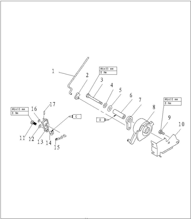
| SH. | PART NO. | DESCRIPTION | QTY | REMARKS |
|---|---|---|---|---|
| 1 | F15-07000015 | LINKACCELEROGRAPB CONTROL | 1 | |
| 2 | F15-07000016 | JOINTACCBLEROGRAPHICONTROL | 1 | |
| 3 | GB/T5782-M6x55 | M6×5S BOLTM6×55 | 1 | |
| 4 | CB/T97.1-6 | 6 WASHER6 | 5 | |
| 5 | CB/T96-6 | 6 LARGE WASHER6 | 1 | |
| 6 | F15-07000012 | BUSHACCBLBROGAAPH ENFORCE | 1 | |
| 7 | F15-07000014 | PULLEYPASSIVITY | 1 | |
| 8 | F15-07000013 | PULLEYDRIVE | 1 | |
| 9 | CB/T5783-M6x10 | M6×10 BOLTM6×10 | 1 | |
| 10 | F15-07000011 | BRACKET,CONTROL TIGBTVIRE | 1 | |
| 11 | CB/T5783-M6x25 | M6×25 BOLTM6×25 | 1 | |
| 12 | CB/T5287-6 | 6 BIGWASHE6 | 1 | |
| 13 | F25-03000027W | PLATE,SBIFT | 1 | |
| 14 | F25-03000028W | BUSH ,LIMITED PLATE | 1 | |
| 15 | F15-05040103W | LINK ROD , SEIFT | 1 | |
| 16 | F15-00000012 | 1.8 SPRING | 1 | |
| 17 | GB/T96-5 | 5 BIGWASBER5 | 1 |
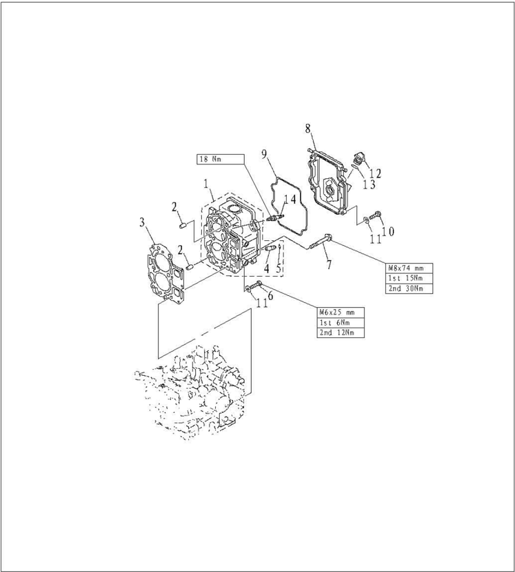
| SN. | PART NO. | DESCRIPTION | DESCRIPTION | QTY | REMARKS |
|---|---|---|---|---|---|
| 1 | F15-07040100 | CYLINDER HEAD ASSY | 1 | ||
| 2 | F15-07000001 | 10x8.4x14HOLLWPIN | 2 | ||
| 3 | F15-07000100 | GASKET,CYLINDER HEAD | 1 | ||
| 4 | F15-07040104 | VALVE GUIDE BUSH | 4 | ||
| 5 | F15-07040105 | CIRCLIP,GUIDE BUSH | 4 | ||
| 6 | GB/T5783-M6x25 | M6X25 | BOLT,HEXAG0NM6X25 | 3 | |
| 7 | F15-07000028 | M8X75BOLTFLANGEM8X75 | 6 | ||
| F15-07050001 | COVER,CYLINDER HEAD | 1 | |||
| 6 | F15-07050002 | SEAL,CYLINDER COVER | 1 | ||
| 10 | GB/T5783-M6x20 | M6X20 | BOLT,HEXAG0N M6X20 | 4 | |
| 11 | GB/T97.1-6 | 6 | WASHER,PLATE6 | 7 | |
| 12 | F15-07050004 | PLUG,OIL | 1 | ||
| 13 | JA80P40431-02S | 0 | O-RING | 1 | |
| 14 | DPR7HS | SPARK PLUG | 2 |
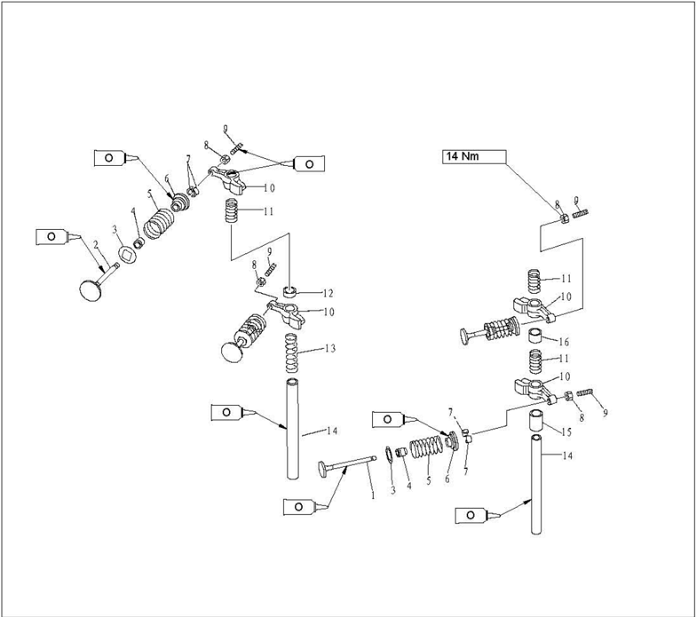
| SN. | PART NO. | DESCRIPTION | DESCRIPTION | QTY | REMARKS |
|---|---|---|---|---|---|
| 1 | F15-07040001 | VALVE,INTAKE | 2 | ||
| 2 | F15-07040002 | VALVE,EXHAUST | 2 | ||
| 3 | F15-07040004 | SEALVALVE SPRING | 4 | ||
| 4 | PS2700.04.03 | SEAL,VALVE STEM | 4 | ||
| 5 | F15-07040005 | SPRING,VALVE | 4 | ||
| 6 | F15-07040006 | RETAINER,VALVE SPRINGRE | 4 | ||
| 7 | F15-07040007 | COTTERVALVE | 8 | ||
| 8 | F15-07040304 | LOCK NUT | 4 | ||
| 9 | F15-07040303 | SCREW,VALVE ADJUSTING | 4 | ||
| 10 | F15-07040301 | ROCKER | 4 | ||
| 11 | F15-07040014 | B | SPRING,ROCKER B | 3 | |
| 12 | F15-07040009 | BUSHER,VALVE INTAKE | 1 | ||
| 13 | F15-07040013 | ASPRING,ROCKERA | 1 | ||
| 14 | F15-07040015 | SHAFT,ROCKER | 2 | ||
| 15 | F15-07040012 | B BUSHER,VALVE EXHAUST B | 1 | ||
| 16 | F15-07040011 | A BUSHER,VALVE EXHAUSTA | 1 |
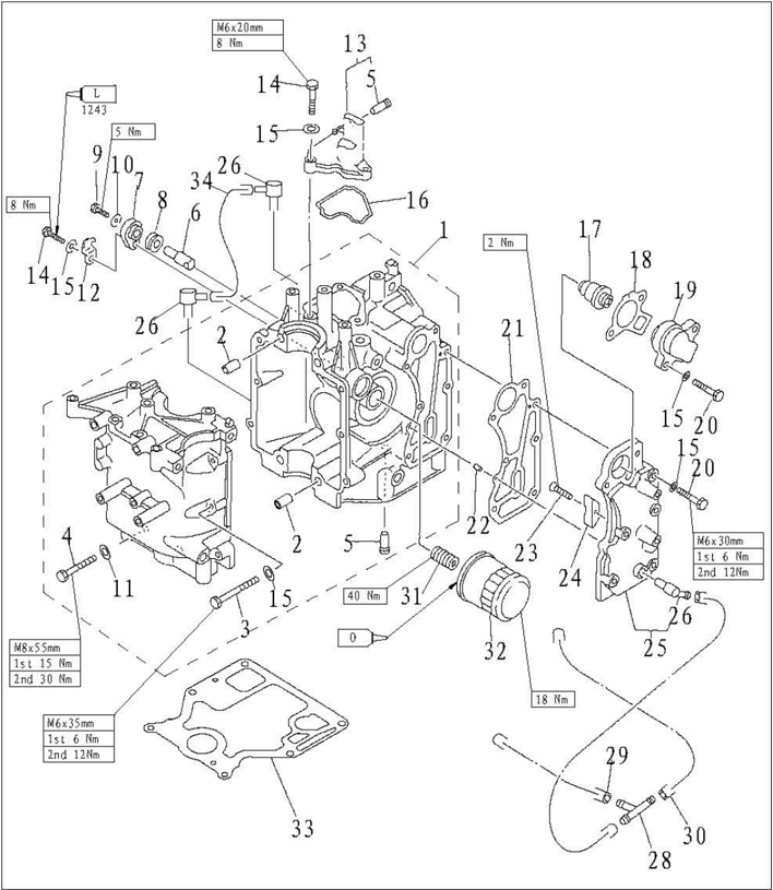
| SN. | PART NO. | DESCRIPTION | DESCRIPTION | QTY | REMARKS |
|---|---|---|---|---|---|
| 1 | F15-07010000 | CRANKCASE ASSY | 1 | ||
| 2 | F15-07000001 | 10x14INH0LL0W | 10x14INH0LL0W | 2 | |
| 3 | GB/T5783-M6x35 | M6X35 | BOLT,HEXAGON M6X35 | 6 | |
| 4 | GB/TS783-M8x35 | M8X55 | BOLT,HEXAGON M8XSS | 4 | |
| 5 | F15-07010006 | PIPE,JOINT | 2 | ||
| 6 | F15-07010008 | ANODE | 1 | ||
| 7 | F15-07010011 | COVER,ANODE | 1 | ||
| 8 | F15-07010009 | GROMMET,ANODE | 1 | ||
| 9 | GB/T5783-MSx12 | MSX12SCREWPANHEAD | MSX12SCREWPANHEAD | 1 | |
| 10 | GB/T97.1-5 | 5 | WASHER5 | 1 | |
| 11 | GB/T97.1-8 | 8 | WASHER5 | 4 | |
| 12 | F15-07010012 | PLATE,ANODE | 1 |
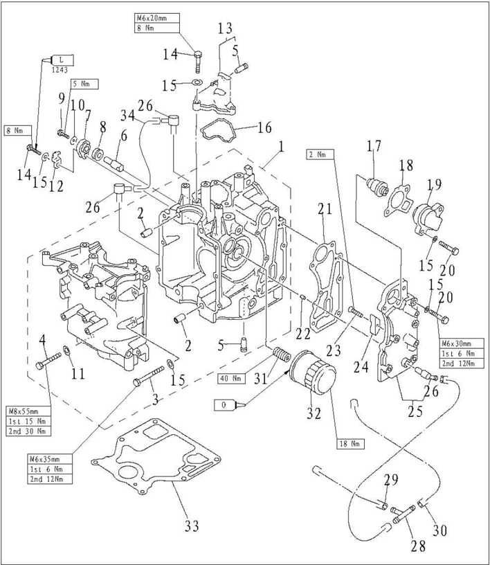
| SN. | PART NO. | DESCRIPTION | DESCRIPTION | QTY | REMARKS |
|---|---|---|---|---|---|
| 13 | F15-07010013 | COVER,BREATHER | 1 | ||
| 14 | GB/T5783-M6x20 | M6X20 | BOLT M6X20 | 4 | |
| 15 | GB/T97.1-6 | 6 | WASHER6 | 17 | |
| 16 | F15-07010014 | BREATHER GASKET | 1 | ||
| 17 | F15-04000036 | THERMOSTAT | 1 | ||
| 18 | F15-07010022 | GASKET,THERMOSTAT | 1 | ||
| 19 | F15-07010021 | COVER,THERMOSTAT | 1 | ||
| 20 | GB/T5783-M6x30 | M6X30 | BOLT M6X30 | 7 | |
| 21 | F15-07010018 | GASKBT,BXHAUST OUTER COVER | 1 | ||
| 22 | F15-00000013 | Φ4x12 | PIN | 2 | |
| 23 | GB/T820-M4x12 | M4X12SCREW | M4X12SCREW | 1 | |
| 24 | F15-07010026 | ANODE |
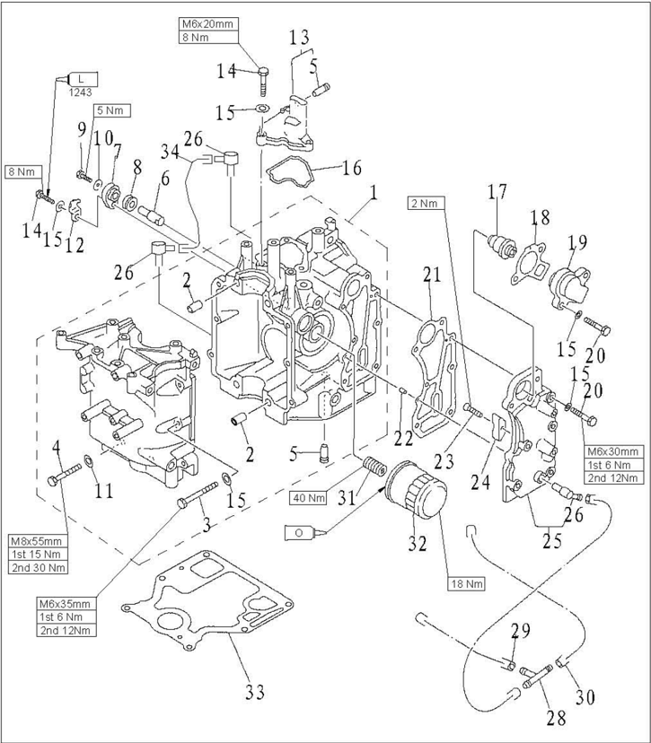
| SN. | PART NO. | DESCRIPTI0N | DESCRIPTI0N | QTY | REMARKS |
|---|---|---|---|---|---|
| 25 | F15-07010019 | OUTER COVER,EXHAUST | 1 | ||
| 26 | F15-04000005 | WATER NIPPLE | 3 | ||
| 27 | F15-05000012 | AΦ10xΦ5x67H0SEA | 1 | ||
| 28 | F15-05000011 | THREE-WAY PIPE | 1 | ||
| 29 | F15-05000013 | B10x5x172H0SEB | 1 | ||
| 30 | F15-05000014 | CΦ10x5x300H0SEC | CΦ10x5x300H0SEC | 1 | |
| 31 | F15-07010003 | BOLT UNION | 1 | ||
| 32 | F15-07010023 | OIL CLEANER | 1 | ||
| 33 | F15-00000014 | GASKET,ENGINE | 1 | ||
| 34 | F15-07010007 | Φ10x5x70 | HOSE,RETURN OIL | 1 |
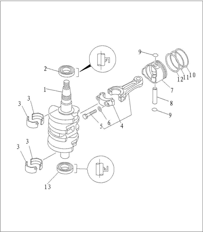
| SN. | PART NO. | DESCRIPTION | QTY | REMARKS |
|---|---|---|---|---|
| 1 | F15-07030000 | CRANKASSY | 1 | |
| 2 | F15-07030006 | A25x40x6.5-LOIL SEALA | 1 | |
| 3 | F15-07010024 | MAIN BEARING | 4 | |
| 4 | F15-07020100 | ROD,CONNECTING | 1 | |
| 5 | F15-07020103 | BOLT,CONNECTING ROD | 2 | |
| 6 | F15-07020104 | WASHER,PLATE | 2 | |
| 7 | F15-07020001 | PISTON | 1 | |
| 8 | F15-07020006 | PIN,PISTON | 1 | |
| 9 | F15-07020005 | CIRCLIP | 2 | |
| 10 | F15-07020002 | I PISTON RING I | 1 | |
| 11 | F15-07020003 | Ⅱ PISTON RINGII | 1 | |
| 12 | F15-07020004 | COMBINATION OIL RING | 1 | |
| 13 | F15-07030007 | B35x47x6.5-R0ILSEALB | 1 |
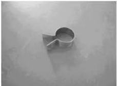
Piston slider
Housing oil seal installer
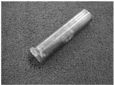
Oil cleaner spanner
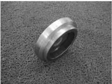
Compression Pressure Inspection
- 1.Start the engine and preheat it for 5 minutes. Then stop it.
- Remove stopper hang rope.
- Remove spark plug and attach pressure gauge to spark plug hole.
CAUTION:
Before removing spark plug, use compressed air to clean the spark plug notch, to prevent dust and other foreignmatter from entering cylinder.
- Open the choke completely, and rotate the crankshaft with starter. When the pressure gauge readings become stable, check the cylinder pressure.
Please don't change the choke position when checking the cylinder pressure.
NOTE:
For models that use control box, remove the throttle link and open completely the carburetor throttle rod by hand, and then measure the pressure.
- If the measured pressure is below the specification or there is difference between cylinders, add a little oil into cylinders and measure again.
Special Tools
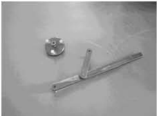
Flywheel gripper and flywhee puller
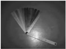
Space gauge
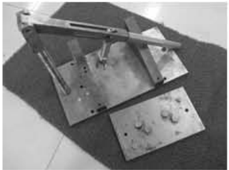
Valve spring compressor
NOTE:
If the cylinder pressure increases continuously, check piston and piston ring for damage. Replace if necessary.
The outboard engine comes with an automatic decompression device, so the pressure data measured may have variance.
If the cylinder pressure doesn't increase at all, check valve clearance, valve, valve seat, cylinder liner, cylinder cover and cylinder cover gasket. Adjust or replace if necessary.
Oil Pressure Inspection
- 1.Start the engine and preheat it for 5 minutes.Then stop it.
- Remove the oil pressure switch and attach the pressure gauge. NOTE:
Please use the pressure gauge equipped with 1/8in pitch thread adapter.
- Check the oil pressure Oil pressure (reference data): 110kPa (idling speed)
Oil Pressure Switch Inspection
- 1.Remove the oil pressure switch and attach the vacuum pressure gauge.
- Load the stated pressure on oil pressure switch.
Inspect the continuity of oil pressure switch with digital circuit tester.Replace if unqualified.
| Pressure | Continuity |
|---|---|
| Above14.7kPa | Discontinuous |
| Below 14.7kPa | Continuous |
- 3.When the engine rpm increases, check the opening pressure of the safety valve.Clean or replace if necessary.
Opening pressure: 388.0~ 450.0kPa
Disassembling Power Unit
- Open the top cowling.
- Remove starter.
- Remove chokes cable and throttle cable.
- Remove carburetor.
- Remove flywheel with special tool.
Flywheel gripper and flywheel puller
- 6.Remove bolts connecting power unit and upper casing.
- 7.Lift the engine and remove the pin.
- 8.Remove oil strainer and safety valve. Check the oil strainer for damage and clog.Replace if necessary. Check the safety valve for damage and crack.Replace if necessary.
- 9.Remove the woodruff key.
- Disconnect the engine stop switch wire and ground wire.
- Remove throttle cable (manual start models) or cable joint (electric start models).
- Remove charge coil, lighting coil and pulsed coil.
- Remove high-pressure assembly, CDI unit, ignition coil, oil pressure switch and spark plug.
Belt Pulley and Timing Belt
- cylinder cover.
CAUTION:
Please don't rotate the flywheel counter clockwise. Otherwise, valve system will be damaged.
- 2.Remove timing belt pulley nut with the special timing belt pulley nut barrel.
NOTE:
Please don't turn camshaft while unscrewing the timing belt pulley.
- Remove timing belt from side of driven belt pulley.
CAUTION:
Please don't rotate the belt pulley before timing belt is fixed. Otherwise, valve system will be damaged.
- Remove driven belt pulley bolt, driven belt pulley and woodruff key.
NOTE:
Please remove driven belt pulley bolt with flywheel gripper.
Please don't rotate camshaft while unscrewing the timing belt pulley.
- Remove nut, limitative plate, timing belt pulley and woodruff key.
- Check belt pulley and timing belt for crack, damage and wear. Replace if necessary.
- 7.Assemble woodruff key and driven belt pulley. Align the mark "1" on the driven belt pulley with the mark *"" on the cylinder cover. Tighten the driven belt pulley bolt temporarily.
CAUTION:
Please don't rotate the belt pulley before timing belt is fixed. Otherwise, valve system will be
- Assemble wood ruff key and timing belt pulley. Align the notch mark on the timing belt pulley with the mark *" on the cylinder body.
- 9.Assemble new timing belt.Remember to put the timing belt part number vertical and upward.
CAUTION:
Please don't distort, rotate or bend the timing belt. Otherwise, it will be damaged.
Please keep timing belt from gasoline or oil.
Please don't rotate belt pulley counter clockwise. Otherwise, the valve system will be damaged.
- Assemble limitative plate and tighten the nut temporarily.
- Rotate timing belt pulley clockwise for two loops to eliminate the slack of timing belt pulley. Check whether alignment marks are aligned well.
- Tighten bolt and nut.
Locking torque: Driven belt pulley bolt 13.4 Nm
Timingbelt pulley nut54Nm
NOTE:
Remove driven belt pulley bolt with flywheel gripper.
Tighten timing belt pulley nut with special timing belt pulley nut barrel.
Disassembling and Inspection
Cylinder Cover
Disassembling
- 1.Remove the bolts of cylinder head cover.
- Remove the bolts of the cylinder cover according to the reverse numbering sequence marks on the cylinder cover.
- 3.Remove the cylinder cover. Remove the oil pump.
- 4.Remove the rocker arm shaft, spring and rocker arm assy.
NOTE:
Before removing rocker arm shaft, unscrew lock nut and adjust screw to slack.
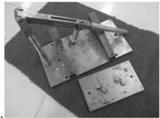
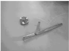
Valve and Valve Guide Bush
- 1 . Inspect the valve seat width. If not in the prescribed range, repair the valve seat.
Valve seat width: 0.6~0.8mm
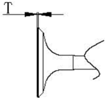
- 2.Inspect the valve margin thickness (T). If not as in the prescribed value, replace the valve.
- Inspect the valve stem diameter. If not in the prescribed range, replace the valve.
The margin thickness of valve: 0.5~0.9mm
Thediameter ofvalve stem:
Intake valve:5.475~5.490mm
Exhaustvalve: 5.460~5.475mm
- Measure the valve stem run out. If exceeding the limit, replace the valve.
Valve stem run out limit: 0.01mm
- 5.Measure the inside diameter of the valve guide bush.
The inside diameter of the valve guide bush: 5.500~5.512mm
CAUTION:
When replacing the valve, use a new valve guide bush and valve oil seal.
Valve Spring
- Measure the free length of valve spring. If less than prescribed value, replace.
- 2.Measure the valve spring tilt.If exceeding the prescribed limit, replace.
The minimum free length: 32.68mm
The maximum tilt limit: 1.5mm
Valve Rocker Arm and Rocker Shaft
- 1.Check the interfacebetween thevalve rocker arm and rocker shaftforwear. Replace if necessary.
- Measurewhether theinsidediameter ofvalverocker arm and outsidediameterofrockershaft are within prescribed value.
The inside diameter ofvalve rocker arm:
13.000~13.018mm
The outside diameter of rocker shaft:
12.941~12.951mm
Camshaft
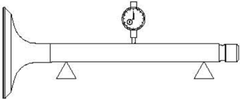
- Check the camshaft size.
Replace if necessary.
| Height | Intake camshaft | 27.596~27.696mm |
|---|---|---|
| Height | Exhaust camshaft | 27.616~27.716mm |
| Base circle diameter | Base circle diameter | 23.950~24.050mm |
- Check camshaft run out.Replace if necessary.
Roundness limit:0.03mm
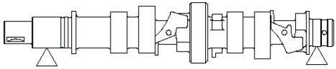
- Check main journal diameter of camshaft and journal inside diameter of cylinder cover. Replace if necessary.
- Check the automatic decompression device for crack and damage.Replace the camshaft if necessary.
- Remove screw and oil pump.
Journalinsidediameterofcylindercover:35.000~35.012mm Main journal diameter: 34.935~34.955mm
Oil Pump Check
- Check rotor clearance of oil pump.Replace if out of specification.
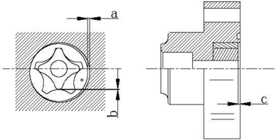
| Clearance between external rotor andcasing a | 0.100~0.150mm |
|---|---|
| Clearancebetweenexternalrotorand internalrotor b | 0.040~0.140mm |
| Clearancebetweenrotor andcoverc | 0.030~0.090 mm |
Valve Guide Bush Replacement
- Knock out the valve guide bush from the direction of combustion room.
- 2.Knock in the new valve guide bush from the direction of the top of cylinder cover.
NOTE:
Coat the oil on the surface of pipe before installation.
- 3.Bore the inside diameter of pipe to the prescribed value by reamer.
Inside diameter of valve pipe:5.500~5.512mm
NOTE:
When taking out the reamer, don’t rotate it in counter clockwise direction.
Valve Seat Inspection
- 1.Clean the carbon on the valve.
- Coat a thin layer of bluing dye evenly onto the seal face of the valve seat.
- 3.Lap the valve on valve seat by valve lapping tool.
- 4.Measure thevalveseatwidth.
The valve face is with bluing dye.
If the valve and valve seat do not match, or the valve seat width does not conform to specified value, reface andlapthevalveseat.
If the contact surface is not even, replace the valve guide bush.
The valve seat width:
The maximum valve seat width:
0.6~0.8mm
1.1mm
Valve Seat Cutting
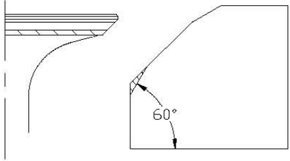
- 1.Use 45° valve seat cutter to adjust the valve seat width.Turn the cutter clockwise until the valve seatfaceissmooth.
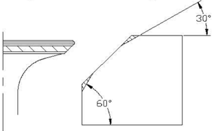
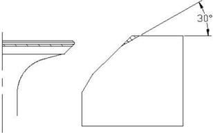
- If thevalve seat is centered on thevalveface but it's toowide,to reduce the valve seat width,use 30° cutter to adjust the top edge of the seat, and use 60° cutter to adjust the bottom edge of the seat.
- 3.If the valve seat is too narrow and on the top edge of valve surface, use 30 ° cutter to adjust the top margin of the seat, and use 45 ° cutter to adjust the valve seat width if necessary.
- If the valve seal surface is too narrow and on the bottom edge of valve surface, use 60° cutter to adjust the bottom edge of the seat, and use 45 ° cutter to adjust the valve seat width if necessary.
- Coat evenly a thin layer of lapping compound ontovalve seat, and lap the valve by lapping tool.
- 6.Clean up the remaining lapping compound.
- Inspect again the valve seat width.
CAUTION:
Do not overlap the valve.Turn the lapping tool evenly with a downward force of 40~50N.Do
Valve Installation
- Install new valve oil seal and spread engine oil to the valve guide bush.
- Install valve, valve spring seal, valve spring and valve spring retainer in sequence.
- Compress the valve spring with valve spring compressor and install valve cotter.
- 4.Knock valve spring retainer slightly with plastic or rubber hammer to fix the valve cotter.
Assembling Cylinder Cover
- Install new oil seal with special tool.
- 2.Install camshaft into cylinder cover from the direction of oil pump.
- Check whether spline position is facing the conjunction sur face of cylinder.Adjust if necessary.
- Install rocker arm assembly, spring and rocker shaft.
- 5.Assemble oil pump.
NOTE:
Ensure mark on the external rotor is facing the oil pump cover.
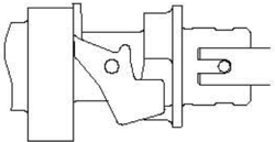
- Align oil pump drive shaft with camshaft pin, then install oil pump.
CAUTION:
Before installing oil pump, make sure the oil passage is through, and fill the oil pump with oil.
NOTE:
Crankcase
Disassembling
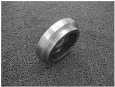
- Remove the oil cleaner with special tool.
Put one piece of cloth under oil cleaner
Oil cleaner spanner
- 2.Remove thermostat cover and gasket.
- Remove exhaust outer cover, gasket and pin. Clean the anode surface and check the anode.Replace if the corrosion of anode is abnormal. Check the exhaust outer cover for crack, distortion or corrosion.Replace if necessary.
- Remove breather. Check the breather body for crack, distortion or corrosion. Replace if necessary.
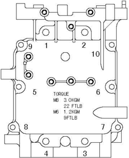
- Remove the crankcasebolts according tobelow drawing,and remove the crankcase.
- Remove the connectingrod bolts and connecting rod cover,remove the crank, and remove connecting rod and piston assy.
- Remove piston pin circlip with pliers, and remove piston pin and piston.
- Remove oil seal, pin and main bearing.
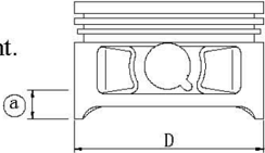
Piston diameter:
58.950~58.965mm
Measuring point@:5mm
Piston
Measure piston outside diameter at the specified measuring point. If out of specification, replace.
Cylinder Bore
- Measure cylinder bore separately at measuring point ①, O, ③. At each point,measure the cylinder bore at places D1,D3,D5 parallel to the crankshaft and at places D2, D4, D6 vertical to the crankshaft.
Measuring point height: ①10mm;
②40mm;
③70mm
Cylinder bore:
59.00~59.02mm
59.10mm
Limit size:
- Calculate taper limit and round limit.If out of specification, replace crankcase.
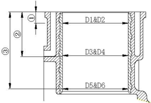
Taper limit: 0.08mm (D1-D5, D2-D6)
Round limit: 0.05mm (D2-D1, D6-D5)
Piston Pin Outside Diameter
Measure piston pin outside diameter. If out of specification, replace the piston pin. Piston pin outside diameter: 13.996~14.000mm
Piston Ring
- Push the piston ring parallel with the piston into the specified measuring point of the cylinder (10mm from conjunction surface).
- Measure end gap by space gauge. If out of specification, replace the piston ring.
- Install piston ring to piston, and measure side clearance between piston ring and its slot by space gauge. If out of specification, replace the piston ring.
End gap (installed):
Top ring
0.15~0.30mnm
2nd ring
0.30~0.50mm
Oil ring
0.2~0.7mm
Side clearance:
Top ring
0.04~0.08mm
2nd ring
0.02~0.04mm
Oil ring
0~0.22mm
Crankshaft
- 1.Measure diameter of crankshaft main journal, crankpin diameter and crankpin width. If out of specification, replace the crankshaft.
- 2.Measure crankshaft run out.If out of specification, replace.
| Diameter of crankshaft main journal | 34.997~35.009 mm |
|---|---|
| Crankpin diameter | 30.997~31.009 mm |
| Crankpin width | 21.00~21.07mm |
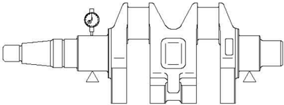
0.05mm
Crankpin Oil Clearance
- 1.Put a piece of plastic space gauge on to the crankpin in parallel to the crankshaft.
Crankshaft run out limit:
- 2.Assemble connecting rod to the crankpin.
- 3.Tighten the connecting rod bolts to the specified torque.
- Remove the connecting rod, measure the compressed width of the plastic space gauge. If out of specification, replace the connecting rod.
Tightening torque:
First tightening
10 Nm
Second tightening
21 Nm
Oil clearance:0.020~0.052mm
NOTE:
Don't rotate the connecting rod before completing measurement.
Main Journal Oil Clearance
- Clean main bearing, main journal and fitting surface of cylinder body and crankcase.
- Install main bearing and crankshaft to cylinder body.
- 3.Put one plastic space gauge on the main journal, paralleling with crankshaft.
NOTE:
Don't put plastic space gauge on the oil hole of main journal.
- 4.Install main bearing onto crankcase and install crankcase onto cylinder body.
- Following the numbering sequence on the crankcase, tighten the bolts at specified torques. Tightening torques:
- Remove crankcase and measure the compressed width of each plastic gauge. If out of specification, replace the main bearing.
| First tightening | M8 | 15 Nm |
|---|---|---|
| Second tightening | M8 | 30 Nm |
| First tightening | M6 | 6 Nm |
| Second tightening | M6 | 12 Nm |
Oil clearance:
0.012~0.045mm
NOTE:
Please don't rotate the crankshaft before themeasurement is completed.
Cylinder Body and Crankcase
- 1.Inspect cylinder body and crankcase for crack, damage or wear. Replace if necessary.
- Inspect cooling water passage for dirt or clog. Clean if necessary.
Full Installation
Piston Connecting Rod Installation
Install piston, connecting rod, piston pin and piston pin circlip
NOTE:
When installing, make sure that the mark on the connecting rod is on the same side as the mark on the piston crown.
Piston Ring Installation
- Install oil ring, 2nd ring and top ring.
NOTE:
Make sure that the mark is toward the piston crown when installing the 2nd ring.
- 2.Picture of the piston ring gap Oil ring end gap 1 (lower rail) Oil ring end gap 2 (expanded ring) Oil ring end gap 3 (upper rail) 2nd piston ring end gap 4 Top piston ring end gap 5
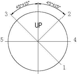
Piston Installation
Use piston slider to install piston, and make sure that the piston crown *Up" is toward the flywheel side.
NOTE:
Apply engine oil to the piston and piston ring side when installing.
Crankshaft Installation
- Install the crankshaft and main bearing to cylinder body. Install oil seal.
NOTE:
Apply grease onto new oil seal before installing.
- Install connecting rod cover, and tighten the connecting rod bolt to the specified torque.
Tighten torque:
First tightening
10 Nm
Second tightening 21Nm
NOTE:
Apply engine oil to moving parts before installing.
Assembling Power Unit
- Install the main bearing to cylinder body.
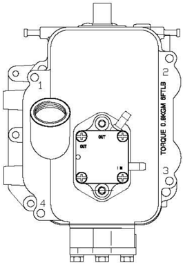
- 2.Apply fluid sealant to conjunction surface of the cylinder body, and install dowel pin and cylinder body. Tighten the bolts twice according to the sequences on the right picture.
Tighten torque
| First tightening | M8 | 15Nm |
|---|---|---|
| Second tightening | M8 | 30Nm |
| First tightening | M6 | 6 Nm |
| Second tightening | M6 | 12 Nm |
NOTE:
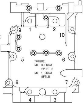
Apply engine oil to moving parts before installing.
- 3.Install bolt union of oil cleaner and tighten it to the specified torque. Tighten torque:40 Nm
- 4.Install breather.
- 5.Install exhaust outer cover,thermostat and thermostat cover. Tighten bolts twice according to priority as picture.
- Install dowel pin, cylinder gasket and cylinder cover assembly.
- Inspect the position of woodruff key slot.
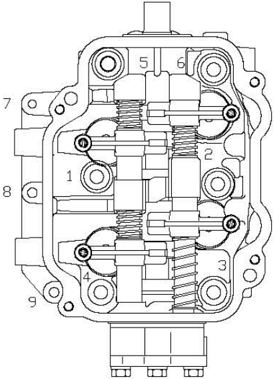
- Tighten the cylinder cover bolts twice to specified torque according to sequences on right picture. Tighten torque:
- Install timing belt pulley, driven belt pulley, timing belt and breather pipe.
- 10.Adjustvalve clearance.
Tighten torque:First tightening
6Nm
Second tightening
12 Nm
| First tightening | M8 | 15 Nm |
|---|---|---|
| Second tightening | M8 | 30 Nm |
| First tightening | M6 | 6 Nm |
| Second tightening | M6 | 12Nm |
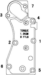
- 11.Install cover of cylinder cover and tighten bolt according tosequences onrightpicture.
- Install throttle cable bracket and accelerograph enforce.
- For electric start models, install gear shift limitative rod firstly.
- Install oil pressure switch, ignition coil, C.D.1. unit assy. and rectifier and regulator assy.
- Install pulsed coil, lighting coil and charge coil.
- Install fuel system.
- Install pressure relief valve and oil strainer.
Upper Unit
Top Cowling
Explosive Drawing
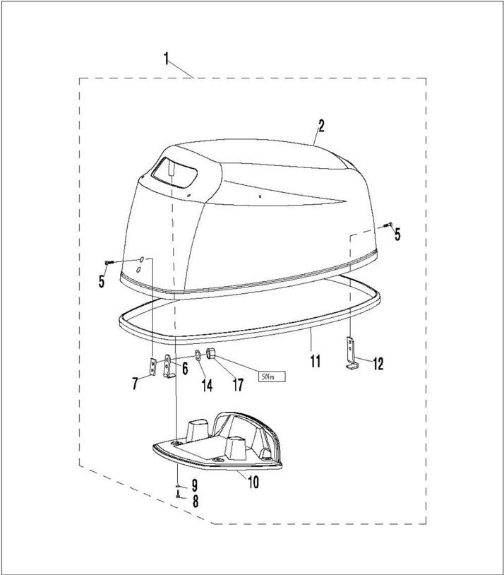
| SN. | PART NO. | DESCRIPT10N | DESCRIPT10N | QTY | REMARKS |
|---|---|---|---|---|---|
| 1 | F15-08000000 | TOP COWLING ASSY | 1 | ||
| 2 | F15-00000001 | TOP COWLING | 1 | ||
| 3 | GB/T818-M5x20 | +M5×20 | SCREW,PAN HEAD M5 ×20 | 2 | |
| 4 | F15-08000004 | POTHOOK | 1 | ||
| 5 | F4-06000006 | UNDERLAY,POTHOOK | 1 | ||
| 6 | GB/T845-ST5.5x19 | ST5.5x19 | SCLEW,TAPPING ST5.5x19 | 4 | |
| 7 | F4-06000004 | UNDERLAY,RUBBER | 4 | ||
| 8 | F15-08000003 | COVER,TOP COVLING MUFFLE | 1 | ||
| 9 | F15-08000002 | SEAL | 1 | ||
| 10 | F15-08000005 | H0OOK, LOCKING | 1 | ||
| 11 | GB/T97.1-5 | 5 | WASHE5 | 4 | |
| 12 | GB/T6170-M5 | MS | NUT M5 | 4 |
- Removerubberseal.
- Remove top cowling muffle cover screw and rubber underlay.
- 3.Remove top cowlingmuffle cover.
- 4.Remove locking hook and pothook.
- 6.Inspect rubber seal for crack or damage.Replace if necessary.
- 7.Inspect top cowling muffle cover for crack or damage.Replace if necessary.
- 8.Inspect lock hook and pothook for crack, deform or damage. Replace if necessary.
Disassembling and Inspection
Bottom Cowling
Explosive Drawing
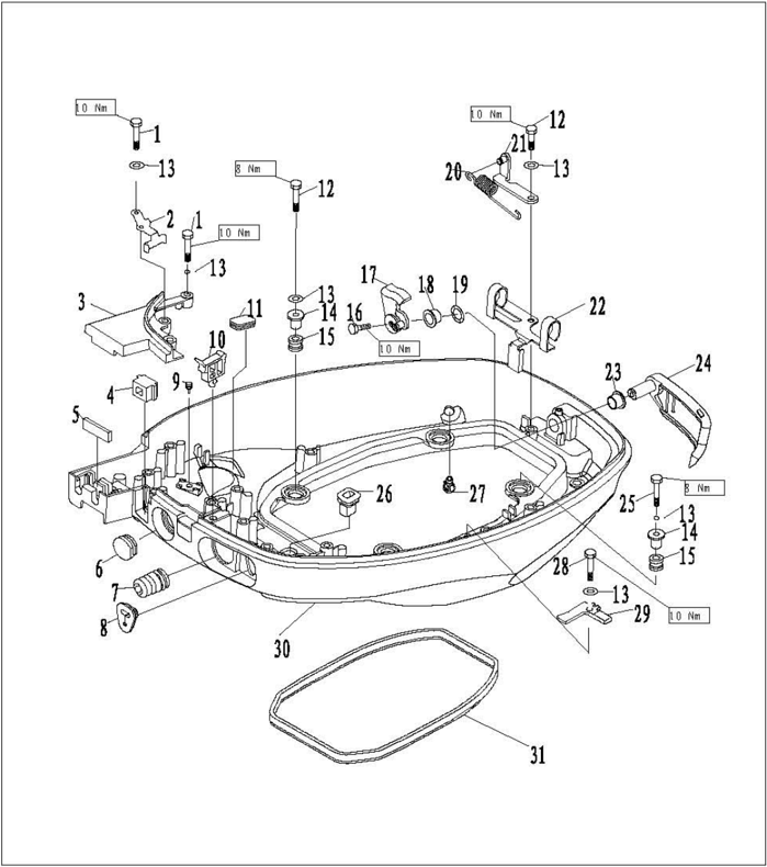
| SN. | PART NO. | DESCRIPTION QTY | DESCRIPTION QTY | REMARKS |
|---|---|---|---|---|
| 1 | CB/T5783-M6x30 | M6X30 | BOLT HBXAGON M6K30 3 | |
| 2 | F15-05000019 | ORIENTBD PLATE,CHOKE 1 | ||
| 3 | F15-05000018 | COVER BOARD,BOTTON COWLING 1 | ||
| 4 | F15-05010002 | SHEATH,CHOKE 1 | ||
| 5 | F15-05000017 | SEAL,RUBBER 1 | ||
| 6 | F15-05000007 | RUBBER PLUG,CIRCULAR 1 | ||
| 7 | F15-05000006 | SHEATE,WAYE 1 | ||
| 8 | F15-01000015 | JACKET,CABLB 1 | ||
| 9 | F15-05000015 | RUBBER PLUG,NEEDLE 1 | ||
| 10 | F15-05000008 | A | CLAMPA 1 | |
| 11 | F15-05000003 | RUBBER PLUG,QUADRATE 1 | ||
| 12 | GB/T5783-M6x25 | H6X25 | BOLT BBXAGON M6X25 2 |
| SN. | PART NO. | DESCRIPTION | QTY | REMARKS |
|---|---|---|---|---|
| 13 | CB/T91.7-6 | 6 | WASHER6 10 | |
| 14 | F15-05000005 | BUSHING,DAMPER 4 | ||
| 15 | F15-05000004 | DAMPER 4 | ||
| 16 | CB/T5783-M6x12 | M6X12 | BOLT,HEXAGON M6X12 1 | |
| 17 | F15-05030000 | LOCKING ASSY,TOP COWLING 1 | ||
| 18 | F15-05000036 | B | BUSHINGB 1 | |
| 19 | F15-05000023 | WASHER,WAVE 1 | ||
| 20 | F15-05000026 | SPRING,TENSION 1 | ||
| 21 | F15-05000025 | RACKETSSYNSIONALNG | ||
| 22 | F15-05000024 | CLIP,WATER PIPB 1 | ||
| 23 | F15-05000022 | A | BUSHINGA 1 | |
| 24 | F15-05020000 | LOCKIKG HANDLE ASSY,TOP COLIRG 1 |
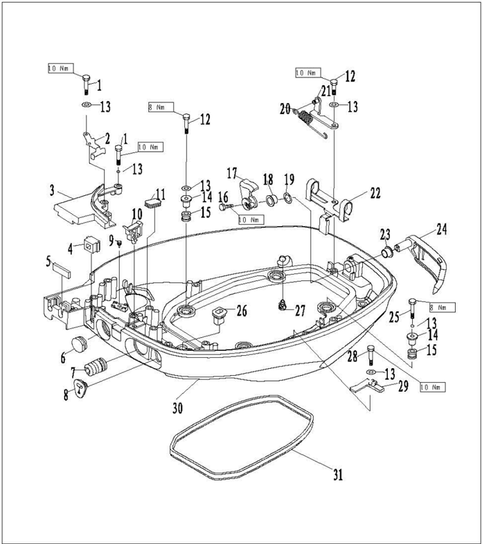
| SN. | PART NO. | DESCRIPTION | QTY | REMARKS |
|---|---|---|---|---|
| 25 | GB/T5783-Mx35 | M6X35 | BOLT, HBXAGON M6X35 2 | |
| 26 | F15-05000033 | JACKET,LEVER 1 | ||
| 27 | F15-05000009 | NIPPLE,PLASTIC 1 | ||
| 28 | GB/T7583-M6x20 | M6X20 | BOLT,HEXAGON M6X20 2 | |
| 29 | F15-05000021 | COVERING 2 | ||
| 30 | F15-05000001 | BOTTOM COWLING 1 | ||
| 31 | F15-05000002 | SEAL,BOTTOM COWLING 1 |
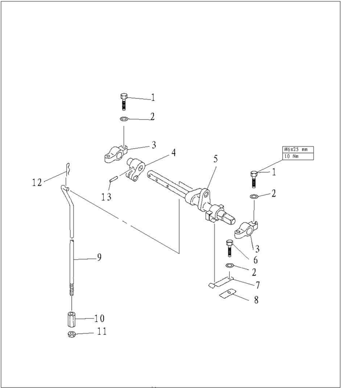
| SN. | PART NO. | DESCRIPTION | DESCRIPTION | QTY | REMARKS |
|---|---|---|---|---|---|
| 1 | CB/T5783-M6x25 | M6×25BOLTM6×25 | 4 | ||
| 2 | GB/T97.1-6 | 6 | WASHER6 | 5 | |
| 3 | F15-05040002 | BRACKET,SHIFT ROD | 2 | ||
| 4 | F15-05040001 | ROCKER,STOPPER | 1 | ||
| 5 | F15-05040100 | LEVER,SHIFT ROD | 1 | ||
| 6 | CB/T5783-M6x20 | M6×20 | BOLTM6×20 | 1 | |
| 7 | F15-05000031 | SPRING | 1 | ||
| 8 | F15-05000032 | STOPPER SPRING | 1 | ||
| 9 | F15-05000034 | SHIFT ROD | 1 | ||
| F15-05000034S | SHIFT ROD | 1 | |||
| 10 | F15-05000035 | COLUMNEDNUT | 1 | ||
| 11 | CB/T41-2000 | ION | 1 | ||
| 12 | CB/T5783-2000 | 0 | SPRING | 1 | |
| 13 | GB/T879.2-3x20 | 3x20 | PIN,SPRING3x20 | 1 |
Disassembling and Inspection
- 1.Remove rubber plug, wave sheath and throttle cable jacket.
- Remove bolts fixing bottom cowling cover board, and remove cover board.
- Remove top cowling locking handle assembly screws, remove top cowling locking handle and top cowlinglockingblock.
- 4.Remove top cowling locking handle bush A and top cowling locking handle bush B.
- 5.Remove wave washer.
- 6.Remove fixing bolt of shift rod bracket.
- 7.Remove cotterpin of shift rod.
- Remove shift rod, spring pin and stopping rocker.
- Remove spring and stopper spring.
- Inspect bottom cowling for crack or damage. Replace if necessary.
- necessary.
- Inspect wave washer and locking handle bush for crack or damage. Replace if necessary.
- Inspect shift rod bracket and stopping rocker for crack or damage.Replace if necessary.
- Inspect spring and stopper spring for crack, crank or damage. Replace if necessary.
Steering Handle
Explosive Drawing

| SN. | PART NO. | DESCRIPTION | QTY | REMARKS | |
|---|---|---|---|---|---|
| 1 | F15-01030004 | THROTTLE CABLE ASSY | 2 | ||
| 2 | F15-01000014 | TUBEWAVE PLASTIC | 2 | ||
| 3 | GB/T889-M10x1.25 | N10×1.25 | LOCKNUT M10×1.25 | 4 | |
| 4 | GB/T6171-M10x1.25 | M10×1.25 | NUT M10×1.25 | 1 | |
| 5 | F15-01000013 | PLATEBANDLE ORIENTATION | 1 | ||
| 6 | F15-01000011 | WASHER ,HANDLE (LOW) | 1 | ||
| 7 | F15-00000007 | EANDLEGEAR SHIFT | 1 | ||
| 8 | F15-00000011 | LINK,SHIFT ROD | 1 | ||
| 9 | GB/T97.1-6 | 6 | WASHER,PLAIN6 | 2 | |
| 10 | F15-00000012 | SPRING,CLAMP | 1 | ||
| 11 | F15-00000009 | WASHER,WAVE | 2 | ||
| 12 | F15-00000008 | TUBEFLANGE | 2 |
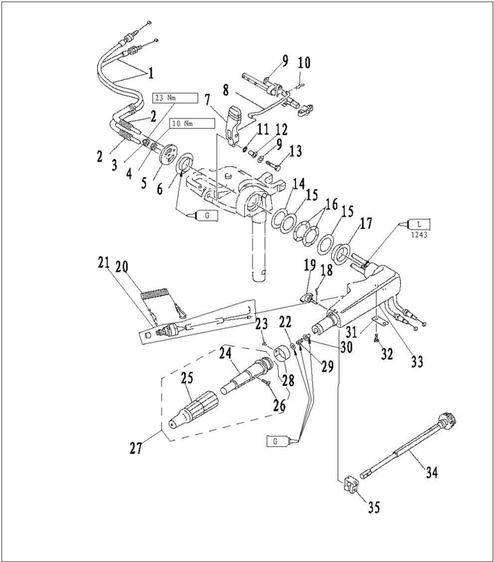
| SN. | PART NO. | DESCRIPTION | QTY | REMARKS |
|---|---|---|---|---|
| 13 | GB/TS783-M6x30 | M6×30 HEXAG0N B0LT M6X30 | 1 | |
| 14 | F15-01000012 | WASHER,NYLON | 1 | |
| 15 | F15-01000008 | WASHER | 2 | |
| 16 | F15-01000009 | WASHER,WAVE | 2 | |
| 17 | F15-01000007 | BUSH HANDLE | 1 | |
| 18 | GB/T91-1.6x12 | 1.6×12 PIN,C0TTERΦ1.6X1 | 1 | |
| 19 | F15-01030200 | BOLT | 1 | |
| 20 | F4-01090401 | STOPER ,HANG ROPE ASSY | 1 | |
| 21 | F4-01090400 | ENGINE STOP SWITCE ASSY | 1 | |
| 22 | GB/T848-10 | 10 SMALL WASHER 10 | 1 | |
| 23 | GB/T827-2x5 | 2×5 RIVBT,SEMICIACLE 2x5 | 1 | |
| 24 | F4-01090301 | GRIPSTEERING HANDLE | 1 |
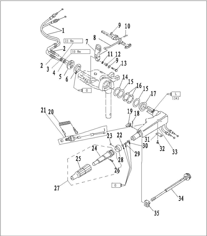
| SN. | PARTNO. | DESCRIPTION | DESCRIPTION | QTY | REMARKS |
|---|---|---|---|---|---|
| 25 | F4-01090302 | RUBBERHANDLE | 1 | ||
| 26 | GB/T820-M5x25 | MS×25 | SCREW M5×25 | 1 | |
| 27 | F4-01090300 | STEERING BANDLE ASSY | 1 | ||
| 28 | F4-01090303 | INDICATOR THROTTLE | 1 | ||
| 29 | F4-01090007 | SPRING,COMPRESSION | 1 | ||
| 30 | F4-01090006 | BUSH | 1 | ||
| 31 | F15-01030005 | STAY | 1 | ||
| 32 | GB/T5783-M6x20 | M6×20 | HEXAG0N B0LT M6X20 | 2 | |
| 33 | F15-01030001 | HANDLE STEERING | 1 | ||
| 34 | F15-01030100 | LEVER,THROTTLE ASSY | 1 | ||
| 35 | F4-01090003 | FRICTION | 1 |
- Remove shift handle.
- Remove steeringhandle cover.
- Remove handle bush, bush washer and wave washer.
- Remove cotter pin and friction adjusting bolt.
- Remove throttle handle.
- Remove throttle cable.
- Remove throttleleverstay and throttlelever.
- Remove engine stop switch.
- Inspect shift handle for crack or damage.Replace if necessary.
- Inspect steering handle for crack or damage. Replace if necessary.
- Inspect bush, bush washer and wave washer for crack or damage. Replace if necessary.
- Inspect throttle cable for wear or crack. Replace if necessary.
- 13.Inspect the conduction of engine stop switch.Replace if out of specification.
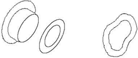
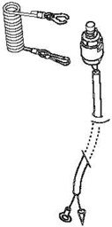
Remove locking plate:
Conducting
Install locking plate:
Not conducting
Push stop switch button:
Conducting
Disassembling and Inspection
Bracket
Explosive Drawing
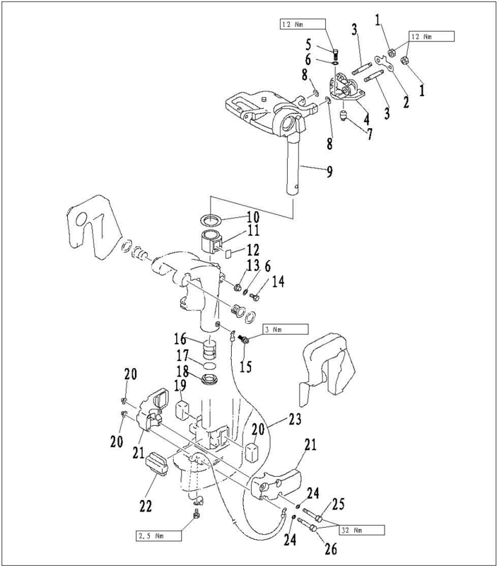
| SN. | PART NO. | DESCRIPTION | QTY |
|---|---|---|---|
| 1 | CB/T6170-M8 | M8 NUTM8 | 2 |
| 2 | F15-00000004 | PLATE | 1 |
| 3 | GB/T900-M8x50 | M8×50BOLTDOUBLEHEADM8XS0 | 2 |
| 4 | F15-02010000 | DOUBLEHOLESHOCKABSORBERASS | 1 |
| 5 | CB/T5783-M6×25 | M6×25 BOLT M6×25 | 3 |
| 6 | CB/T97.1-6 | WASHER6 | 3 |
| 7 | F15-02010003 | 6 SEALWATER TUBE | 1 |
| 8 | F15-00000016 | LARGE WASHER | 2 |
| 9 | F15-01020001 | BRACKETHELM | 1 |
| F15-01020001S | BRACKETHELM | 1 | |
| 10 | F15-01000003 | WASHER,ABOVE | 1 |
| 11 | F15-01000001 | BUSH,ABOVE | 1 |
| 12 | F15-01000002 | PLATELOCK | 1 |
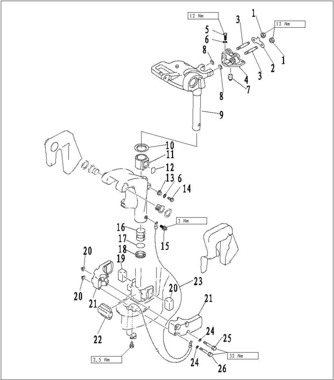
| SN. | PART NO. | DESCRIPTION | QTY | REMARKS |
|---|---|---|---|---|
| 13 | F15-01010303 | SEALLOCK BOLT | 1 | |
| 14 | CB/T5783-M6x20 | M6×20 BOLT M6×20 | 1 | |
| 15 | JB/T7940.1-M6 | M601LER | 1 | |
| 16 | F15-01000004 | BUSHBELOW | 1 | |
| 17 | CB/T3452.1-30x3.55 | 030×3.55 0-RING30×3.55 | 1 | |
| 18 | F15-01000006 | WASHERBELOW | 1 | |
| 19 | F15-00000002 | MOORT DAMPER,LEFT AND RIGHT | 2 | |
| 20 | CB/T6177-M8 | M8NUTM8 | 4 | |
| 21 | F15-00000001 | SHBLL ,HOUNI DAMPER | 2 | |
| 22 | F15-00000003 | MOUNT DAMPERFAORT | 1 | |
| 23 | F15-02000003 | B TIGHIVIREEARTHING | 1 | |
| 24 | GB/T97.1-8 | 8 WASHER8 | 4 | |
| 25 | CB/T5782-M8x105 | M8×105 BOLT M8×105 | 2 | |
| 26 | CB/T5782-M8x85 | M8×85 BOLT M8×85 | 2 |
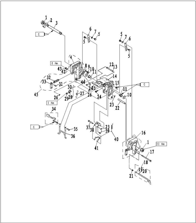
| SN. | PART NO. | DESCRIPTION | QTY |
|---|---|---|---|
| 1 | F15-01010007 | NUTSELF-LOCKING PLATE,TWO HOLE | 2 |
| 2 | F15-01010003 | 1 | |
| 3 | F15-01010001 | BOLTCLAMPBRACKBT | 1 |
| 4 | F15-01010201 | BRACKETRIGHT | 1 |
| 5 | F15-01010103 | SCREWFLAT EXAGON | 4 |
| 6 | F15-01010105 | PLATETILT STOPPER | 2 |
| 7 | F15-01010104 | VASBBR,WAVE | 1 |
| 8 | F15-01010202 | A TIGHTWIRE,EARTHING | 1 |
| 9 | CB/T818-M6x8 | M6×8SCREWPAEEADM6x8 | 1 |
| 10 | F15-01010002 | TASHER,NYLON | 2 |
| 11 | F15-01010302 | BUSBROTARYBRACKET | 2 |
| 12 | F15-01010308 | BUSBINGORIENTATION | 1 |
| 13 | F15-01010309 | VASHER,NYLON | 1 |
| 14 | F15-01010301 | BRACKET,ROTARY | 1 |
| F15-01010301S | BRACKET,ROTARY | 1 |
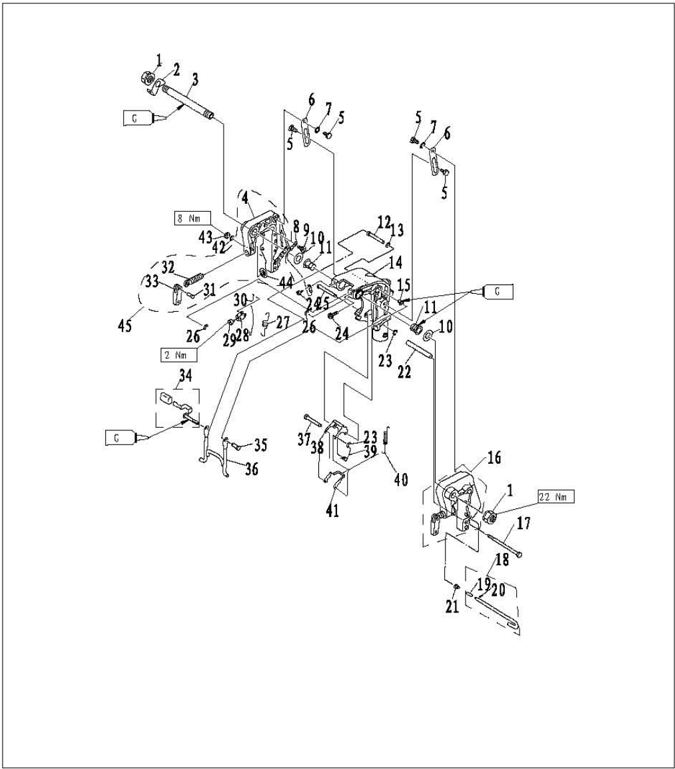
| SN. | PART NO. | DESCRIPTION | QTY | REMARKS |
|---|---|---|---|---|
| 15 | F15-01010311 | BUSHMYLON | 1 | |
| 16 | F15-01010100 | LEFT BRACKET ASSY | 1 | |
| 17 | CB/T5782-M6x145 | M6×145 BOLTM6×145 | 1 | |
| 18 | F15-01010400 | LIMITATIVE ROD ASSY | 1 | |
| 19 | F4-01050003 | NOGPREYENTED UNLOCK | 1 | |
| 20 | CB/T879.1-3x8 | 3×8 PIN,SPRING3x8 | 1 | |
| 21 | F15-01010402 | CONICAL SPRING | 1 | |
| 22 | F15-01010006 | TUBE,BOLT | ||
| 23 | CB/T896-4 | 4 CIRCLIP4 | 2 | |
| 24 | CB/T818-M8x10 | M8×10SCREWPANBBADM8×10 | 2 | |
| 25 | F15-01010316 | LONG SHAFT,LOCK ANGLE | 1 | |
| 26 | CB/T896-5 | 5 CIACLIPS | 2 | |
| 27 | F15-01010304 | SPRINGTENSION | 1 | |
| 28 | F15-01010306 | LEVER,ANGLE ORIENTATION | 1 | |
| 29 | CB/T818-M5x6 | M5x6SCREWPANEADM5x6 | 1 |
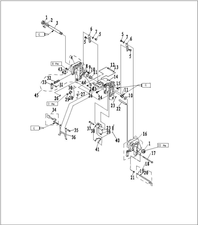
| SN. | PART NO. | DESCRIPT10N | QTY | REMARKS |
|---|---|---|---|---|
| 30 | F15-01010307 | ROD,TILT LOCK | 1 | |
| 31 | F4-01010005 | RIVETCLAMPHANDLE | 2 | |
| 32 | F15-01010102 | SCREW,CLAMP | 2 | |
| 33 | F4-01010004 | CLAMPSHIPBOARDBANDLE | 2 | |
| 34 | F15-01010305 | TILT CLAMP HANDLE ASST | 1 | |
| 35 | F15-01010312 | SHAFT,STOPPER | 1 | |
| 36 | F15-01010313 | SUPPORT ASSY | 1 | |
| 37 | F15-01010317-3 | SHORT SHAFT ,LOCK ANGLE | 1 | |
| 38 | F15-01010317-2 | BRACKBT,LOCI ANGLE | 1 | |
| 39 | F15-01010315 | SPRING,TORSION | 1 | |
| 40 | F15-01010314 | SPRING,TENSION | 1 | |
| 41 | F15-01010317-1 | INNER BRACKET | 1 | |
| 42 | GB/T848-6 | 6 WASHER6 | 1 | |
| 43 | GB/T6170-M6 | M6 NUT N6 | 1 | |
| 44 | F4-01010003 | CLAMP PLATE | 2 | |
| 45 | F15-01010200 RIGHT BRACKET ASSY | 1 |
Disassembling and Inspection
- 1.Remove limitative rod and bolt (M6X145).
- 2.Remove nut and bolt of tilt stopper plate, and remove the tilt stopper plate.
- 3.Remove clamp bracket nut, two hole plate, and double head bolt of clamp bracket.
- 4.Remove clamp bracket.
- 5.Remove rotary bracket.
- Remove lock angle handle and tilt lock rod. Remove tension spring and angle orientation lever.
- 7.Remove orientation bushing and nylon bush.
- 8.Remove lock angle long shaft and short shaft.
- Remove lock angle bracket, torsion spring, tension spring and inner bracket.
- Inspect rotary bracket and clamp bracket for damage or crack.Replace if necessary.
- Inspect bush and gasket for damage or crack. Replace if necessary.
- Inspect lock angle bracket and support bracket for deform. Replace if necessary.
Upper Unit Parts
Explosive Drawing
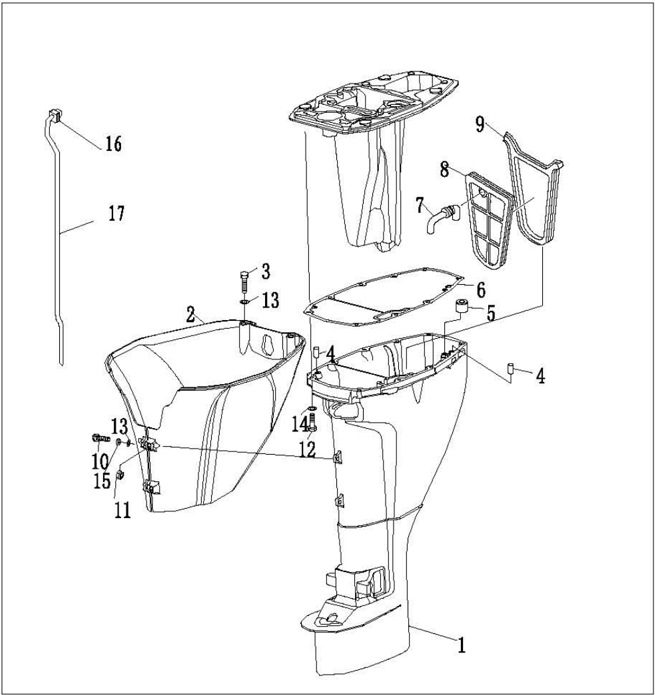
| SN. | PART NO. | DESCRIPTI0N | QTY | REMARKS | |
|---|---|---|---|---|---|
| 1 | F15-02000001 | UPPER CASING | 1 | L | |
| F15-02000001S | UPPER CASING | S | |||
| 2 | F15-00000015 | MANTLE,UPPER CASING | |||
| 3 | GB/T5783-M6x16 | M6X16HEXAG0NB0LTM6X16 | |||
| 4 | F15-00000006 | PIN,DOWEL | 2 | ||
| 5 | F15-02000007 | SEAL | 1 | ||
| 6 | F15-00000005 | GASKET | 1 | ||
| 7 | F15-03000002 | RUBBER PIPEEXHAUST | 1 | ||
| 8 | F15-03000001 | CLAPBOARD,EXHAUST | 1 | ||
| 9 | F15-03000003 | SEAL,CLAPBOARD | 1 | ||
| 10 | GB/T818-M6x25 | M6X25BOLT | M6X25BOLT | 2 | |
| 11 | GB/T41-2000 | NUT,HEXAGON | 2 | ||
| 12 | GB/T5783-M8x45 | M8X45BOLTHEXAGONM8X45 | 6 | ||
| 13 | GB/T97.1-6 | 6 | WASHER6 | 4 | |
| 14 | GB/T97.1-8 | 8 | WASHER8 | 6 | |
| 15 | GB/T93-6 | 6 | WASHER,SPRING | 2 | |
| 16 | F15-02000006 | QUADRATE SEAL,WATER PIPB | |||
| 17 | F15-02000005 | TUBE,WATER | |||
| F15-02000005S | TUBE,WATER | 1 | S |
Disassembling and Inspection
- Remove the oil sump.
- Remove the oil seal and abnormity seal.
- 3.Remove the exhaust pipe, oil drain bolt, oil drain jacket and exhaust pipe seal.
- 4.Remove double hole shock absorber assy, water pipe quadrate seal and water pipe.
- 5.Check the upper casing for crack or wear. Replace if necessary.
- Check water pipe for deform or erosion.Replace if necessary.
- Check exhaust clapboard for damage, wear or crack. Replace if necessary.
Lower Unit (Detailed)
Water Pump Assembly
Explosive Drawing
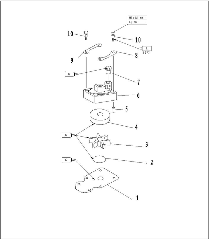
| SN. | PART NO. | DESCRIPTION | QTY | REMARKS | |
|---|---|---|---|---|---|
| 1 | F15-06000007 | OUTER PLATE | 1 | ||
| 2 | JASO F404-96 | 031-45 | 0-RING 31-45 | 1 | |
| 3 | F15-06050000 | IMPELLER | 1 | ||
| 4 | F15-06060002 | INNER SHELLVATER PUMP | 1 | ||
| 5 | F15-00000013 | 4X12 | PIN,D0WEL4X12 | 2 | |
| 6 | F15-06060001 | WATERPOMP HOUSING | 1 | ||
| 7 | F15-02000004 | UPPBR SEALWATER PIPE | 1 | ||
| 8 | F15-06060004 | SEAL | 1 | ||
| 9 | F15-06000014 | FIXED PLATE, WATER PUMP | 2 | ||
| 10 | CB/T5783-M8x45 | M8X45 | BOLT,HEXACON M8X45 | 4 |
Disassembling and Inspection
- 1.Remove water pump fixed plate.
- 2.Remove water pump housing.
- 3.Remove impeller and water pump inner shell.
- Removewoodruffkey and outerplate.
- Check water pump housing and outer plate for crack, crank or damage. Replace if necessary.
- Check inner water pump inner shell and impeller for crack, deform, burn or damage. Replace if necessary.
Lower Unit Gears
Explosive Drawing
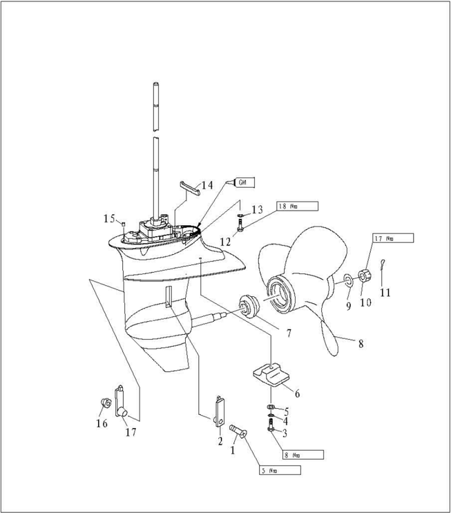
| SN. | PART NO. | DESCRIPTI0N | DESCRIPTI0N | QTY | REMARKS |
|---|---|---|---|---|---|
| 1 | GB/T820-M5x25 | M5x25 | SCREW M5X25 | 1 | |
| 2 | F15-06000003 | B | WATER INLET B | 1 | |
| 3 | GB/T5783-M6x30 | M6X30 | BOLT,HEXAGON M6X30 | 1 | |
| 4 | GB/T97.1-6 | 6 | WASHER6 | 1 | |
| 5 | CB/T861.1-6 | 6 | WASHER,LOCKING6 | 1 | |
| 6 | F15-06000004 | ANODE | 1 | ||
| 7 | F15-06000015 | CUSHION,PROPELLER | 1 | ||
| 8 | F15-06090000 | PROPELLER ASSY | 1 | ||
| 9 | GB/T96-10 | 10 | WASHER 10 | 1 | |
| 10 | F15-06000016 | NUT,HEXAGON | 1 | ||
| 11 | GB/T91-2.5x20 | 2.5X20 | PIN,COTTER 2.5X20 | 1 | |
| 12 | GB/T5783-M8x30 | M8X30 | BOLT,HEXAGON M8X30 | 4 | |
| 13 | GB/T97.1-8 | 8 | WASHER8 | 4 | |
| 14 | F15-06020005 | SEAL,RUBBER | 1 | ||
| 15 | F15-00000013 | Φ4X12 | PIN,DOWEL 4X12 | 2 | |
| 16 | GB/T6182-M5 | MSNUTLOCKINGM5 | MSNUTLOCKINGM5 | 1 | |
| 17 | F15-06000002 | A | WATER INLET A | 1 |
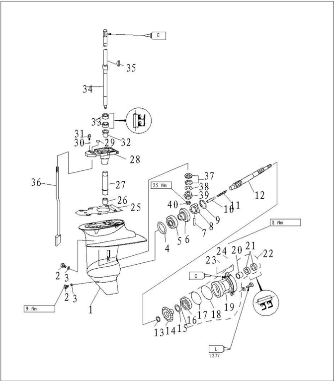
| SN. | PART NO. | DESCRIPTION | QTY | REMARKS |
|---|---|---|---|---|
| 1 | F15-06000001 | LOWER CASING | 1 | |
| 2 | F4-03000023 | PLUC,OIL HOSE | 2 | |
| 3 | F4-03000024 | GASKET | 2 | |
| 4 | F15-06000010-1 | F15-06000010-1t0.10SHIMt:0.10MM | ||
| F15-06000010-2 | F15-06000010-2t:0.12SHIMt:0.12MM | |||
| F15-06000010-3 | F15-06000010-3t:0.15SHIM1:0.15MM | |||
| F15-06000010-4 | F15-06000010-4t:0.18SHIMt:0.18MM | |||
| F15-06000010-5 | F15-06000010-5t:0.30SHIMt:0.30MM) | |||
| F15-06000010-6 | F15-06000010-6t:0.40SHIMt:0.40MM | |||
| F15-06000010-7 | F15-06000010-7t:0.50SHIMt:0.50MM | |||
| 5 | NTN4T-302051L | BEARING | 1 | |
| 6 | F15-06010000 | CEAR,FORWARD | 1 | |
| 7 | F15-06070004 | PIN,CLUTCH | 1 | |
| 8 | F15-06070003 | CLUTCH,DOG | 1 | |
| 9 | F15-06070005 | RING,CLUTCH | 1 |
| SN. | PART NO. | DESCRIPTION | QTY | REMARKS |
|---|---|---|---|---|
| 10 | F15-06070006 | PLUNCER,SHIFT | 1 | |
| 11 | F15-06070002 | SPRING,CLUTCH | 1 | |
| 12 | F15-06070001 | SHAFT,PROPELLER | 1 | |
| 13 | F15-06070007 | WASHER,REVERSE CEAR | 1 | |
| 14 | F15-06080005 | CEAR,REVERSE | 1 | |
| 15 | F15-06080006-1 | t:0.10SHIMt:0.10MM | ||
| F15-06080006-2t:0.20SHIMt:0.20MM | ||||
| F15-06080006-3t:0.30SHIMt:0.30MM | ||||
| F15-06080006-4t:0.40SHIMt:0.40MM | ||||
| F15-06080006-5 | F15-06080006-5t:0.50SHIMt:0.50MM | |||
| 16 | CB/T276-6005 | 6005BEARING6005 | 1 | |
| 17 | F15-06080002 | OAO-RINGA,COVER | 1 | |
| 18 | F15-06080003 | OBO-RINCB,COVER | 1 | |
| 19 | F15-06080001 | COVER,LOWER CASING | 1 | |
| 20 | K0Y0 17BM2312 | 17BM2312 BEARING17BM2312 | 1 |
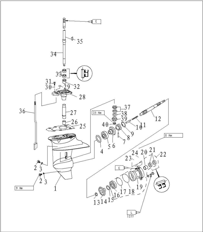
| SN. | PART NO. | DESCRIPTION | DESCRIPTION | QTY |
|---|---|---|---|---|
| 21 | F15-06080004 | 17X30x6 OIL SEAL | 17X30x6 OIL SEAL | 2 |
| 22 | F15-06080000 | COVER ASSY,LOWER CASINC | 1 | |
| 23 | CB/T97.1-6 | 6 | WASHER6 | 2 |
| 24 | CB/T5783-M6x20 | M6X20 | BOLT,HEXAGON M6X20 | 2 |
| 25 | F15-06000005 | WASHER | 1 | |
| 26 | NSK F1420 | F1420 | BEARING F1420 | 1 |
| 27 | F15-06000006 | BUSHINC,NYLON | 1 | |
| 28 | F15-06020001 | BASE,DRIVE SHAFT | 1 | |
| 29 | F15-06020004 | 0 | O-RING | 1 |
| 30 | CB/T97.1-8 | 8 | WASHER8 | 2 |
| 31 | CB/T5783-M8x25 | M8X25 | BOLT,HEXACON M8X25 | 2 |
| 32 | F15-06020002 | BEARING | 1 | |
| 33 | F15-06020003 | 20X30X6 | OILSEAL,DRIVE SHAFT 20X30X6 | 2 |
| 34 | F15-06040000 | DRIVE SHAFT ASSY | 1 | |
| F15-06040000S | DRIVE SHAFT ASSY | 1 |
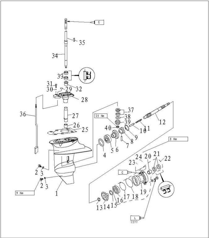
| SN. | PART NO. | DESCRIPTION | QTY | REMARKS |
|---|---|---|---|---|
| 35 | F15-06000013 | KEY,WOODRUFF | 1 | |
| 36 | F15-06030000 | CAM ASSY,SHIFT ROD | 1 | L |
| F15-06030000S | CAMASSY,SHIFT ROD | 1 | S | |
| 37 | F15-06000020 | BEARING | 1 | |
| 38 | F15-06000008 | t:1.13SHIMP1NIONt:1.13MM | 1 | |
| F15-06000009 | t:1.20SHIM,PINIONt:1.20MM | 1 | ||
| 39 | F15-06000011 | PINION | 1 | |
| 40 | F15-06000012 | M8X1NUTPINI0NM8X1 | 1 |
Disassembling and Inspection
- Drain oil, and remove the cotter pin.
- Put a piece of wood between propeller and anti-swirl baffle.Remove hexagon nut, anode and water inlet.
- Remove propeller assembly and cushion.
- Remove anode.
- Remove the lower casing cover. Remove reverse gear and shim. Remove oil seal.
- Remove propeller shaft assembly.
- 7.Remove shift plunger.
- Remove clutch ring, remove clutch pin and dog clutch. Remove clutch spring.
- 9.Remove the drive shaft by using female spline spanner. Remove forward gear.
- Remove drive shaft base.
- Remove shift rod cam assy.
- Remove rolling needle bearing from lower unit.
- Remove oil seal and barrel bearing with guard board from the drive shaft base.
Rolling needle bearing installer
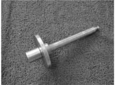
Propeller Shaft and Clutch Block
- Check dog clutch for crack or damage. Replace if necessary.
- Check propeller shaft for wear or crank.Replace if necessary.
- Check the run out of propeller shaft. If out of specification, replace.
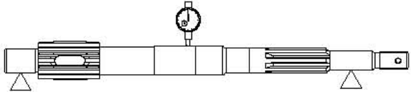
Run out limit: 0.05mm
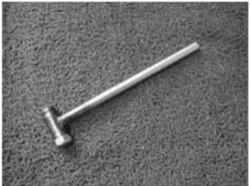
Female spline spanner
Dog Clutch Installation
- 1.Put clutch spring into the hole at the end of the propeller shaft.
- Install the dog clutch as shown.Make sure the "F" mark is toward the forward gear. Install clutch pin.
- Install clutch ring and shift plunger.
- Install oil seal.

- Install bearing.
NOTE:
Install oil seal and bearing by using special tools.
Take note of the direction and depth when installing the oil seal.
Make sure the manufacturer mark of the bearing is toward the reverse gear.
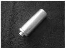
Lower casing cover bearing installer
Lower casing cover oil seal installer
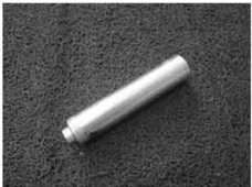
Lower casingcover barrel bearing installer
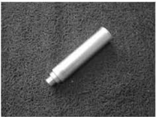
Lower Casing Cover
- Check bearing for rust or rumbling when run.Replace if necessarily.
- Remove bearing and oil seal by bearing puller.
NOTE:
Don't remove bearing unless changing it.
- 3.Remove rolling needle bearing by using special tool.
NOTE:
Use new parts when reinstalling the oil seal and rolling needle bearing.
- Clean casing cover by a soft brush and solvent.
- Check casing cover for crack or damage. Replace if necessary.
Lower Casing Cover Oil Seal and Bearing Installation
- Install reverse gear and shim.
NOTE:
Adjust the shim when install the new reverse gear and bearing.
Drive Shaft
- Inspect the drive shaft for crank or wear.Replace if necessary.
- 2.Check the run out of drive shaft.
Run out limit: 0.05 mm

Shift Rod Cam
Check the shift rod cam for wear or deform. Replace if necessary.
Gear
Inspect the forward gear, reverse gear and pinion for wear or damage. Replace if necessary.
Forward Gear Bearing
Inspect bearing for rust or rumbling when rotating. Replace if necessary.
NOTE:
Adjust the shim when install new bearing.
Lower Casing Inspection
Check lower casing for crack or damage, check cooling water inlet for clog. Replace if necessary.
Assembling Lower Casing
- Install the rolling needle bearing by using special tool.
- Install new taper roller bearing (if replace).
- Install barrel bearing with guard board. Align the notch on the bearing shoulder with the notch on the drive shaft base.
Rolling needle bearing installer
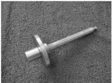
Bearing block copper sleeve installer
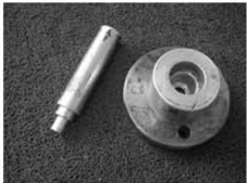
- Install oil seal. (unit: mm)
CAUTION:
Adjust shim when install new driveshaft base or drive shaft. Adjust shim when install new end thrust bearing.
- Tighten the pinion.
Specified torque:
25 Nm
- Install propeller shaft assy.
- Install lower casing cover.
- Check if gearshift works normally.
- Install water pump assy.
- 11.Install anode and water inlet.
- Install propeller and hexagon nut. Put a piece of wood between propeller and anti-swirl baffle. Tighten the nut according to specified torque.
Specified torque:
17Nm
NOTE:
If the nut slot is not aligned with the hole of the propeller shaft cotter pin, tighten the nut until aligned.
Lower Unit Installation
- Install dowel pin.
- Move the shift rod cam assy to reverse gear position. Install the lower unit to upper casing, tighten the bolt according to specified torque.
- Install nylon bushing, shift rod cam assy, gasket, and drive shaft base. Install forward gear, drive shaft, shim, end thrust bearing and pinion.
Bearing block oil seal installer
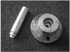
Forward gear bearing installer
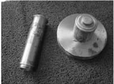
- 3.Connect the columned nut and shift rod cam assy. Change shift, and check if the operation is normal.Adjust the columned nut position if necessary.T Tighten the nut thoroughly.
- Add gear oil using thepressurefilling device.
Shim Selection
T1、T2、T3:Shim thickness
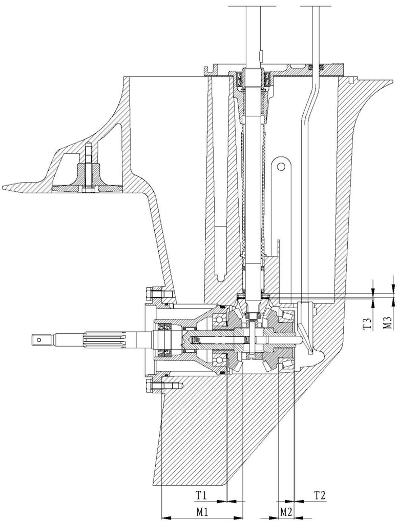
M1: Reverse gear thickness; M2: Forward gear thickness; M3: Thrust rolling needle bearing with flat seat thickness
Calculateformula:
T1=80.57-M1
T2=16.60-M2
T3=6.05-M1
NOTE:
Use three measuring points when measuring the thickness. Apply the average. For the optional shim specs, refer to page 11.
Common Troubles and Solutions
| Trouble type | Possible reason | Recovery action |
|---|---|---|
| Starter will not operate | Starter components arefaulty | Repair or replace |
| Starter will not operate | Shift lever is not in the neutral position | Move to the neutral position |
| Engine will not start | Fuel tank is empty | Fill tank with clean,fresh fuel |
| Engine will not start | Fuel is contaminated or stale | Fill tank with clean,fresh fuel |
| Engine will not start | Gasoline cleaner is obstructed | Replace |
| Engine will not start | Fuel pump is faulty | Inspect or replace |
| Engine will not start | Airvent screwnot loosened | Loosen air vent screw |
| Engine will not start | Spark plug(s) fouled or of incorrect type. | Inspect spark plug(s). Clean or replace withrecommended type |
| Engine will not start | Spark plug cap(s) fitted incorrectly | Check and re-fit cap(s) |
| Engine will not start | Ignition wiring is faulty | Check wires. Tighten all loose connections. Replace worn or broken wires |
| Engine will not start | Ignition parts are faulty | Replace |
| Engine will not start | Engine stop switch lanyard is not attached | Attach lanyard |
| Engine will not start | Engine inner parts are damaged | Repair |
| Engine idles irregularly or stalls | Spark plug(s) fouled or of incorrect type. | Inspect spark plug(s).Clean or replace with recommended type |
| Engine idles irregularly or stalls | Fuel system is obstructed | Checkforpinched orkinkedfuel line or other obstructions in fuel system |
| Engine idles irregularly or stalls | Fuel is contaminated or stale | Fill tank with clean, fresh fuel |
| Engine idles irregularly or stalls | Fuel cleaneris obstructed | Replace |
| Engine idles irregularly or stalls | Spark plug clearance is incorrect | Inspect and adjust as specified |
| Engine idles irregularly or stalls | Ignition wiring is faulty | Check wires.Tighten all loose connections. Replaceworn orbrokenwires |
| Engine idles irregularly or stalls | Specified engine oil is not being used | Check and replace oil as specified |
| Engine idles irregularly or stalls | Thermostat is faulty | Replace |
| Engine idles irregularly or stalls | Carburetor is faulty | Replace |
| Engine idles irregularly or stalls | Fuel pump is faulty | Replace |
| Engine idles irregularly or stalls | Airvent screw on fuel tank is not loosen | Loosen air vent screw |
| Engine idles irregularly or stalls | Fuel joint connection is incorrect | Connect correctly |
| Engine idles irregularly or stalls | Choke knob is pulled out | Return to home position |
| Engine idles irregularly or stalls | Motor angle is too high | Return tonormal operating position |
| Engine power loss | Propeller is damaged | Repair or replace propeller |
| Engine power loss | Trim angle is incorrect | Adjust trim angle to achieve most efficient angle |
| Engine power loss | Motorismountedatincorrect transom height | Adjust motor to proper transom height |
| Engine power loss | Boat bottom is fouledwith marine growth | Clean boat bottom |
| Engine power loss | Weeds or other foreign matter are tangled on gear housing | Remove foreign matter and clean lower unit |
| Engine power loss | Spark plug(s) fouled or of incorrect type. | Inspect spark plug(s). Clean or replace with recommended type |
| Engine power loss | Fuel system is obstructed | Check for pinched or kinked fuel line or other obstructions infuel system |
| Engine power loss | Fuel cleaner is obstructed | Replace |
| Engine power loss | Fuelis contaminated or stale | Fill tank with clean,fresh fuel |
| Engine power loss | Spark plug clearance is incorrect | Inspect and adjust as specified |
| Engine power loss | Ignition wiring is faulty | Check wires. Tighten all loose connections. Replace worn or broken wires |
| Engine power loss | Ignition parts have failed | Replace |
| Engine power loss | Specified engine oil is not being used or oil is added too much | Check and replace oil as specified, or adjust engine oil to specified position |
| Engine power loss | Thermostat is faulty | Replace |
| Engine power loss | Fuel pump is faulty | Replace |
| Engine power loss | Fuel joint connection is incorrect | Connect correctly |
| Engine power loss | Specified spark plug(s) are not being used | Check and replace spark plug(s) as specified |
| Engine vibrates excessively | Propeller is damaged | Repair or replace propeller |
| Engine vibrates excessively | Propeller shaft is damaged | Replace |
| Engine vibrates excessively | Weedsor other foreign matter are tangled on propeller | Remove and clean propeller |
| Engine vibrates excessively | Motor mountingbolt is loose | Tighten bolt |
| Engine vibrates excessively | Steering pivot is loose | Tighten steering pivot |
| Engine vibrates excessively | Steering pivot is damaged | Replace |