Parsun F50/F60 Outboard Motor Service Manual
Table of contents
- Overview
- Specifications
- Repair Information
- Dimensions
- Basic Maintenance
- Electrical System
- Fuel System
- Engine
- Upper Casing
- Upper casing unit and Brackets
- Lower Casing Part
- Decomposition Schematic Diagram (D/T model)
- Decomposition Schematic Diagram (CD/CT model)
- Disassembling and Check
- Propeller Shaft and Clutch Block
- Install the Claw Clutch
- Lower casing Unit Casing Cover
- Forward Gear Bearing
- Check the Lower casing Unit Casing
- Check the Water Pipe
- Assemble the Lower casing Device Casing
- Install the Lower casing Unit
- Selection of Shims
- Common Faults and Solutions
Overview
Identification Marks
The serial number of the outboard motor is printed on a label, which is attached to the port side of the clamp bracket or the upper part of the rotary bracket. The serial number is shown in the whitespace of the label to help you order spare parts from the dealer or for reference when the engine is stolen.
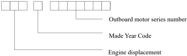
- SN of the outboard motor
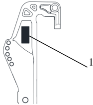
The SN indicates the following:
Propeller Selection
The performance of the outboard motor is seriously affected by the selection of propellers. Improper propeller may have adverse effects on the engine. When running with heavy load, the engine will run at low speed for a long time.
At this time, the propeller with smaller pitch should be selected, otherwise the pitch should be selected.
Larger propeller to maintain normal operation of the engine.
When the engine is running at full throttle, refer to the speed and fuel performance of the engine for the most suitable propeller. In this way the propeller can provide the highest performance.
| Model | Propeller Dimension | Material |
|---|---|---|
| C/D Model Gear ratio: 1.85:1 Gear box capacity:430cc | 3-11 " 8 3 ×12" | Aluminium alloy |
| C/D Model Gear ratio: 1.85:1 Gear box capacity:430cc | 3-11 " 8 1 ×13" | Aluminium alloy |
| CD/CT Model Gear ratio: 2.0:1 Gear box capacity:610cc | 3-13 " 4 1 ×17" | Aluminium alloy |
| CD/CT Model Gear ratio: 2.0:1 Gear box capacity:610cc | 3-13 " 8 5 ×13" | Aluminium alloy |
Protective Measure at Work
In order to prevent hazards or accidents during maintenance and improve work quality, please observe the following safety regulations.
- Fire control
Gasoline and various lubricating oils and greases are highly combustible, so please keep away from heat sources, sparks and open flames when working.
- Ventilation Gasoline steam and engine exhaust gas are highly toxic. Massive inhalation of them can

cause shock and even death. Maintain good ventilation conditions when debugging the engine indoors.
- Self-protection
Wear protective glasses when drilling, grinding or using air compressors. Wear protective gloves and safety shoes when necessary.
- Use of lubricants and sealants
When maintaining and repairing outboard motors, only products provided or recommended by Parsun can be used.
Under normal circumstances, the lubricants mentioned in this Manual will not damage your skin. However, please take protective measures before use to reduce risks.
○ 1 Apply protective cream to both hands before overhauling outboard motors;
○ 2 If clothes are contaminated by lubricant, replace and clean them as soon as possible.
○ 3 Avoid contact with skin;
○ 4 Please wash your hands and skin carefully with soap and hot water after touching lubricant.
○ 5 Use a clean, non-fuzzing rag to wipe off the spilled grease.
- Developing good working habits
○ 1 Tighten nuts, bolts and screws according to the specified torque from the center outward and from large ones to small ones.
○ 2 Use recommended special tools to avoid damage to parts. Use the right tools in the right way.
Disassembling and Assembling
When disassembling and assembling an outboard motor, please observe the following principles:
- Use special tools when disassembling and assembling parts;
- Remove dust and dirt before disassembling parts;
- Apply engine oil to the contact surface of moving parts before assembly;
- When installing the bearing, place the manufacturer's mark in the specified direction and lubricate it fully.
- Before installation, coat a thin layer of waterproof lubricating oil on the protruding part and periphery of the oil seal;
- After the assembling is completed, check whether the moving parts are working properly.
Disposable Parts
Parts such as gaskets, oil seals, O-rings, cotter pins and spring rings are disposable parts and must be replaced when reinstalling the outboard motor.
Inspection before Delivery
In order to ensure the normal use of the products by customers, please carry out the following inspections before delivery.
- Check the fuel system.
Check that the fuel hose is securely connected and that the fuel tank is full of fuel.
Attention:
This is a four-stroke engine and premixed fuel cannot be used.
- Check oil level.
- 1 Check engine oil level.
Pull out the oil dipstick and observe the oil level through the oil dipstick.
- Oil dipstick 2. High position mark 3. Low position mark
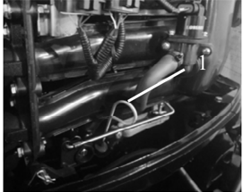
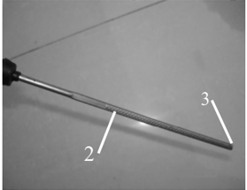
Ensure that the oil level is between the high position mark and the low position mark; Drain the oil when the oil level is higher than the high position mark, and add oil when it is lower than the low position mark.
○ 2 Check gear oil level
Unscrew the oil level hole plug and observe whether there is oil overflow from the oil level plug hole.
If yes, install the oil level hole plug and tighten it according to the specified torque. If not, fill in oil.
1.Oil level hole plug
- Check the steering system. Check whether the steering is smooth;
- Check shift and throttle operation. Check whether the gear shift operation is smooth; Check whether the throttle grip
operates smoothly from the fully closed position to the fully open position.
- Check the emergency stop switch assembly.
Check whether the engine stops when the emergency stop switch assembly is pressed or the motor stop safety rope is pulled out.
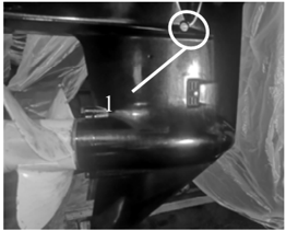
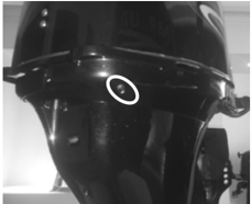
- Check the cooling water observation hole. When the engine is running, check whether the cooling
water is flowing out of the cooling water observation hole.
- Cooling water observation hole
- Running-in operation.
- ① The 1 st hour: Run the engine at 2000 rpm or at about half the throttle.
- ② The 2 nd hour: Run the engine at 3000 rpm or at about 3/4 of the throttle.
- ③ Next 8 hours: Avoid running the motor at full throttle for 5 consecutive minutes.
- Check after running-in operation
- ① Check the gear oil for water.
- ② Check the fuel oil pipeline for leaks.
- ③ After running-in operation, run the engine at idle speed and flush the cooling water channel with fresh water using flushing tools.
- After running-in operation, check the idle speed of the engine.
- ① Preheat the engine for 5 minutes.
- ② Use a tachometer to measure the idle speed of the engine.
Make corresponding adjustment if it does not conform to the specified value. Idle value: 750 ~ 850rpm.
- ③ Turn the throttle stop screw clockwise or counterclockwise until the specified idle speed is reached.
- ④ After adjusting the idle speed, speed up several times to check the stability of the engine.
Attention:
Idle speed adjustment needs to be carried out by qualified maintenance personnel using professional equipment; Random adjustment may cause starting difficulties, weakness, jitter and other faults of the engine.
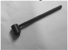
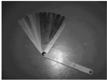
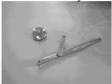
Special Tools and Testing Equipment
Various special tools and testing equipment will be used in the repair and maintenance of outboard motors. Skilled and correct use of these tools and equipment can help improve your work efficiency avoid damage to personnel and outboard motors. Special tools:
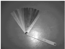
Clearance gauge Piston slideway Flywheel gripper and flywheel puller
Oil filter spanner Bearing puller Valve spring compressor kit
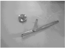
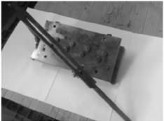

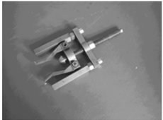
Bearing mounting tool Oil seal mounting tool Needle bearing mounting tool Lower unit Lower unit Lower unit
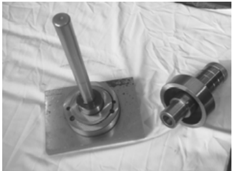

Shell cover tool Needle bearing tool Drive shaft bearing
Drive shaft bearing Drive shaft seat oil seal Forwarder gear bearing mounting tool mounting kit mounting tool kit
Lower unit Lower unit cover mounting tool
Drive shaft spline sleeve Pinion nut wrench
Testing equipment:
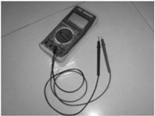
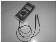
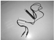
Digital tachometer Digital multimeter Peak voltage adapter
Decomposition Schematic Diagram and Symbolic Description
Decomposition schematic description
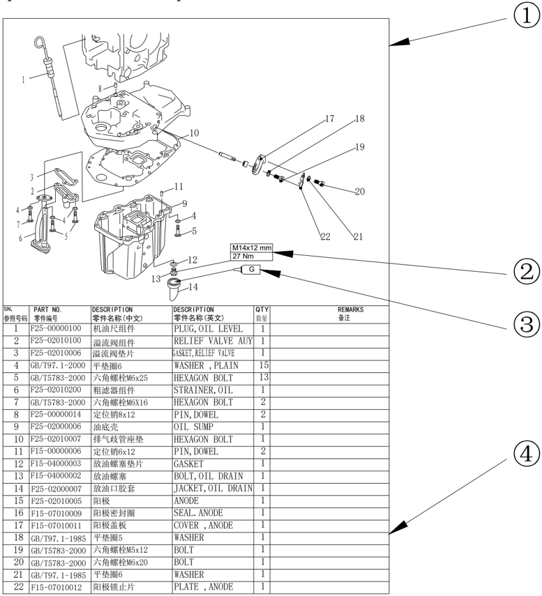
- 1 Decomposition schematic diagram of parts.
- 2 Thread specification and specified torque.
- 3 Application point of oil, sealant or locker.
- 4 Parts list
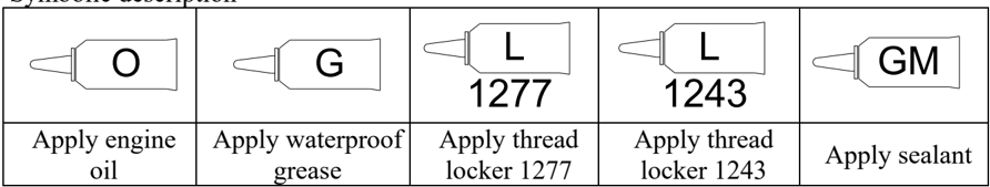
Symbolic description
O
G
L
1277
L
1243
GM
Apply engine oil
Apply waterproof grease
Apply thread locker 1277
Apply thread locker 1243
Apply sealant
Specifications
Parameters of Outboard Motor
| Category | Specification | Detail | Value | Category | Specification | Value |
|---|---|---|---|---|---|---|
| Dimension | Overall length (BE/FE) | Overall length (BE/FE) | 1383/713mm | Engine | Spark plug | DPR7EA-9 (NGK)) |
| Dimension | Overall width | Overall width | 427mm | Engine | Cooling system | Water cooling |
| Dimension | Overall height | D/T | 1435mm | Engine | Exhaust system | Through the propeller hub |
| Dimension | CD/CT | 1476mm | Engine | Lubrication system | Pressure lubrication | |
| Dimension | Height of stem board | Height of stem board | 508mm | Fuel type | Ordinary unleaded gasoline | |
| BEL-D/BEL-CD | BEL-D/BEL-CD | 113 kg/126.5 kg | Fuel grade | PON86 | ||
| BEL-T/BEL-CT | BEL-T/BEL-CT | 114.5 kg/128 kg | Engine oil type | Four-stroke engine oil | ||
| FEL-T/FEL-CT | FEL-T/FEL-CT | 113.5 kg/127 kg | Engine oil grade API SAE | SE, SF, SG, SH, SJ | ||
| Performance | Max. output | F50 | 36.8Kw@5500 r/min | Engine oil grade API SAE | 10W30, 10W40 | |
| Performance | Max. output | F60 | 44.1Kw@5500 r/min | Engine oil level | 2.2L (replace filter) | |
| Performance | Full throttle operating range | Full throttle operating range | 5000 ~ 6000 r/min | Engine oil level | 2.0L (do not replace filter) | |
| Performance | Max. fuel consumption | F50 | 18.5 L/h@6000 r/min | Gear oil type | Hypoid gear oil | |
| Performance | Max. fuel consumption | F60 | 20 L/h@6000 r/min | Gear oil grade API | GL-4 | |
| Performance | Idle (neutral) | Idle (neutral) | 800±50 r/min | SAE | 90 | |
| Engine | Engine type | Engine type | In-line four-stroke, overhead cam | Gear oil level D/T CD/CT | 0.43L | |
| Engine | Number of cylinder | Number of cylinder | 4 | Gear oil level D/T CD/CT | 0.61L | |
| Engine | Displacement | Displacement | 996 cm³ | Bracket | Tilt raise angle | 69° |
| Engine | Bore×Stroke | Bore×Stroke | 65 mm×75mm | Bracket | Steering angle | 40°+40° |
| Engine | Compression ratio | Compression ratio | 9.3 | Bracket | Trim angle | -4° ~ 20° (when stem board is 12°) |
| Engine | Oil supply mode | Oil supply mode | Electronically controlled fuel injection | Drive device | Gear | F-N-R |
| Engine | Control mode | BE | Steering handle | Drive device | Transmission ratio D/T | 2.08 |
| Engine | Control mode | FE | Remote control | Drive device | CD/CT | 2.0 |
| Engine | Starting mode | Starting mode | Electrical starting | Drive device | Gear type | Spiral bevel gear |
| Engine | Ignition system | Ignition system | ECU | Drive device | Clutch type | Claw clutch |
| Engine | Ignition timing | TDC | 2°±0.5° | Drive device | Propeller shaft type | Spline |
| Engine | Ignition timing | BTDC | 25°±0.5° | Drive device | Propeller direction | Clockwise (rear view) |
Repair Information
Engine
| Category | Item | Detail | Data | Category | Item | Detail | Data |
|---|---|---|---|---|---|---|---|
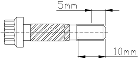
| Min. compression pressure | Min. compression pressure | 840 kPa | Diameter of piston | Diameter of piston | Diameter of piston | 64.950~64.965mm 5mm (from | |
| Lubricating oil pressure | Lubricating oil pressure | 100 kPa | Height of measuring point | Height of measuring point | Height of measuring point | bottom of piston) | |
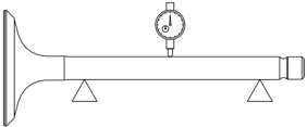
| Bending limit | Bending limit | 0.03mm | Piston-to-cylinder clearance | Piston-to-cylinder clearance | Piston-to-cylinder clearance | 0.035~0.065mm | |
| Inside diameter of camshaft bore | Inside diameter of camshaft bore | 37.00~37.02mm | Piston pin hole aperture | Piston pin hole aperture | Piston pin hole aperture | 15.974~15.985mm | |
| Inner diameter of shaft hole of rocker arm | Inner diameter of shaft hole of rocker arm | 16.000~16.01mm | Piston pin outer diameter | Piston pin outer diameter | Piston pin outer diameter | 15.965~15.970mm | |
| Cylinder bore | Cylinder bore | 65.00~65.013mm | Piston ring | Top ring | Thickness | 1.17~1.19mm | |
| Wear limit | Wear limit | 65.1mm | Piston ring | Top ring | Width of end face | 2.25~2.4mm | |
| Taper limit | Taper limit | 0.08mm | Piston ring | Top ring | End gap | 0.15~0.30mm | |
| Roundness limit | Roundness limit | 0.05mm | Piston ring | Backlash | Backlash | 0.02~0.06mm | |
| Second ring | Thickness | 1.47~1.49mm | Free length | Free length | 40.0mm | ||
| Second ring | Width of end face | 2.60~2.80mm | Min. free length | Min. free length | 38.4mm | ||
| Second ring | End gap | 0.30~0.50mm | Tilt limit | Tilt limit | 1.7mm | ||
| Second ring | Backlash | 0.02~0.06mm | Inner diameter of small end | Inner diameter of small end | 15.985~15.998mm | ||
| Oil ring | Thickness | 2.36~2.48mm | Inner diameter of big end | Inner diameter of big end | 36.000~36.016mm | ||
| Oil ring | Width of end face | 2.75mm | Large head oil clearance | Large head oil clearance | 0.020~0.052mm | ||
| Oil ring | End gap | 0.20~0.70mm | Thickness of big-end | Ablack | 1.496~1.490mm | ||
| Oil ring | Backlash | 0.04~0.18mm | Thickness of big-end | B brown | 1.490~1.484mm | ||
| Height | Intake cam | 30.83~31.03mm | Type | Type | Cycloid pump | ||
| Height | Exhaust cam | 30.83~31.03mm | Pressure relief valve opening pressure | Pressure relief valve opening pressure | 382~442 kPa | ||
| Diameter of base circle | Diameter of base circle | 25.90~26.10mm | Clearance between outer rotor and casing | Clearance between outer rotor and casing | 0.09~0.15mm | ||
| Journal diameter | Journal diameter | 36.935~36.955 mm | Clearance between outer rotor and inner rotor | Clearance between outer rotor and inner rotor | 0.12mm | ||
| Roundness limit | Roundness limit | 0.03mm | Clearance between rotor and cover | Clearance between rotor and cover | 0.03~0.08mm | ||
| Clearance between journal and oil | Clearance between journal and oil | 0.045~0.085mm | Diameter of crankshaft main journal | Diameter of crankshaft main journal | 42.984~43.000 mm | ||
| Valve clearance (Cold state) | Intake valve | 0.15~0.25mm | Crank pin diameter | Crank pin diameter | 32.984~33.000 mm | ||
| Valve clearance (Cold state) | Exhaust valve | 0.25~0.35mm | Crank pin width | Crank pin width | 21.00~21.07mm | ||
| Valve cone width | Intake valve | 1.84~2.97mm | Crankshaft big-end backlash | Crankshaft big-end backlash | 0.05~0.22mm | ||
| Valve cone width | Exhaust valve | 1.98~3.11mm | Roundness limit | Roundness limit | 0.05mm | ||
| Width of contact with race | Intake valve | 0.9~1.1mm | Opening temperature | Opening temperature | 58~62ºC | ||
| Intake valve | 0.8mm | Full open temperature | Full open temperature | 70ºC | |||
| Edge thickness | Exhaust valve | 0.9mm | Mini. opening height of valve | Mini. opening height of valve | 3mm | ||
| Head diameter | Intake valve | 31.9~32.1mm | Displacement | Displacement | 70 L@6000 r/min | ||
| Exhaust valve | 25.9~26.1mm | Pressure | Pressure | 49kPa | |||
| Intake valve | 5.475~5.490mm | Plunger stroke | Plunger stroke | 5.85~9.65mm | |||
| Rod diameter | Exhaust valve | 5.460~5.475mm | Inner diameter of crankshaft main journal | Inner diameter of crankshaft main journal | 46.000~46.024mm | ||
| Inner diameter of guide pipe | Inner diameter of guide pipe | 5.500~5.512mm | Clearance between crankshaft main journal and oil clearance | Clearance between crankshaft main journal and oil clearance | 0.012~0.044mm | ||
| Clearance between pipe and valve stem | Clearance between pipe and valve stem | 0.025~0.052mm | Thickness of crankshaft bearing bush | A black | 1.500~1.494mm | ||
| Valve stem roundness limit | Valve stem roundness limit | 0.03mm | Thickness of crankshaft bearing bush | B brown | 1.494~1.488mm |
Measurement conditions:
Ambient temperature 20 ℃.
- Data for information only
Lower casing Installation
| Category | Item | Data | Item | Data |
|---|---|---|---|---|
| Backlash | Pinion to spur gear | 0.18~0.54mm | Optional gear shim | 0.10,0.12,0.15,0.18, 0.30,0.40,0.50 mm |
| Backlash | Pinion to reverse gear | 0.71 ~ 1.07mm | Optional gear shim |
Electrical System
Ignition and Ignition Control System
| Category | Item | Data | Category | Item | Data |
|---|---|---|---|---|---|
| Ignition timing | At idle speed | TDC 2º±0.5° | Magneto resistance (Green-Green) | Magneto resistance (Green-Green) | 0.59±0.1Ω |
| Ignition timing | Optional gear filler plate | BTDC 25°±0.5º | Peak output of electronic igniter Voltage Rectifier regulator | Secondary output voltage | ≥ 34KV |
| Spark plug clearance | Spark plug clearance | 0.8~0.9mm | Peak output of electronic igniter Voltage Rectifier regulator | Primary resistance | 2.2±0.22Ω |
| Trigger coil | Peak voltage | ≥13 V@1000 r/min | Peak output of electronic igniter Voltage Rectifier regulator | Secondary resistance | 9.84±0.98KΩ |
| Trigger coil | Resistance* | 260 ~ 290 Ω | output peak voltmeter | 1500 r/min (no load) | 41.9V |
| Magneto output peak voltage | 1500 r/min (no load) | 47.2V | output peak voltmeter | 3500 r/min (no load) | 99.8V |
| Magneto output peak voltage | 3500 r/min (no load) | 106V |
Locking Torque
Specified Torque
| Position | Detail | Name | Thread specification | Torque |
|---|---|---|---|---|
| Spark plug | - | - | - | 18 Nm |
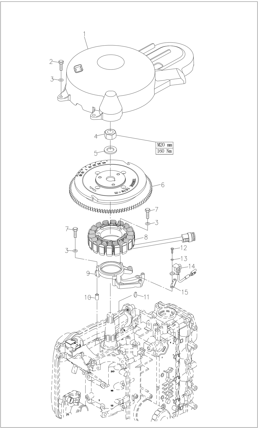
| Flywheel | - | Nut | M20 | 160 Nm |
| Cylinder head | 1st tightening | Bolt | M9 | 23 Nm |
| Cylinder head | 2nd tightening | Bolt | M9 | 47 Nm |
| Cylinder head | 1st tightening | Bolt | M6 | 6 Nm |
| Cylinder head | 2nd tightening | Bolt | M6 | 12 Nm |
| Oil filter | - | - | - | 18 Nm |
| Oil filter stud | - | - | - | 40 Nm |
| Lock nut (rocker arm) | - | Nut | M6x0.75 | 14 Nm |
| Engine assembly | - | Bolt | M8 | 21 Nm |
| Exhaust cover plate | 1st tightening | Bolt | M6 | 6 Nm |
| Exhaust cover plate | 2nd tightening | Bolt | M6 | 12 Nm |
| Thermostat cover | - | Bolt | M6 | 7 Nm |
| Crankcase | 1st tightening | Bolt | M8 | 15 Nm |
| Crankcase | 2nd tightening | Bolt | M8 | 30 Nm |
| Crankcase | 1st tightening | Bolt | M6 | 6 Nm |
| Crankcase | 2nd tightening | Bolt | M6 | 12 Nm |
| Connecting rod | 1st tightening | Bolt | M6 | 6 Nm |
| Connecting rod | 2nd tightening | Bolt | M6 | 17 Nm |
| Driven pulley | Driven pulley | Bolt | M10 | 38 Nm |
| Lower casing assembly | Lower casing assembly | Bolt | M10 | 40Nm |
| Ring nut | Ring nut | - | - | 105Nm |
| Water inlet | Water inlet | Screw | M5 | 5 Nm |
| Oil drain bolt | Oil drain bolt | Bolt | - | 7Nm |
| Oil check hole | Oil check hole | Bolt | - | 7 Nm |
| Pinion gear | Pinion gear | Nut | M22 | 95 Nm |
| Propeller nut | Propeller nut | Nut | M14 | 35 Nm |
| Steering handle | Steering handle | Nut | M10 | 10 Nm |
| Steering handle | Steering handle | Self-locking nut | M10 | 22 Nm |
| Exhaust manifold | Exhaust manifold | Bolt | M6 | 10 Nm |
| Throttle grip | Throttle grip | Screw | M5 | 3 Nm |
| Shift linkage bracket | Shift linkage bracket | Bolt | M6 | 10 Nm |
| Gear spring piece | Gear spring piece | Bolt | M6 | 10 Nm |
| Bottom cover flat | Bottom cover flat | Bolt | M6 | 10 Nm |
| Clamp bracket | Clamp bracket | Self-locking nut | - | 45 Nm |
| Oil drain bolt | Oil drain bolt | Bolt | M14 | 27 Nm |
| Inclined cylinder end | Inclined cylinder end | Screw | - | 90 Nm |
| Tilting motor | Tilting motor | Screw | M5 | 4 Nm |
| Fuel tank cap | Fuel tank cap | - | - | 6.5 Nm |
| Trim cylinder end | Trim cylinder end | Screw | - | 80 Nm |
| Tilt piston | Tilt piston | Bolt | M12 | 61 Nm |
| Pressure relief valve bracket | Pressure relief valve bracket | Bolt | M5 | 5.3 Nm |
| Gear pump assembly | Gear pump assembly | Bolt | M6 | 6.5 Nm |
| Gear pump bracket | Gear pump bracket | Bolt | M5 | 5.3 Nm |
| Trigger coil | Trigger coil | Screw | - | 4 Nm |
| Nut | - | 30 Nm | ||
| Starter motor | Starter motor | Bolt | M8 | 30 Nm |
| Starter motor terminal | Starter motor terminal | Nut | - | 7 Nm |
| Magneto coil | Magneto coil | Bolt | M6 | 7 Nm |
General Torque
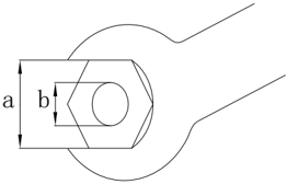
| Nut a | Bolt b | Torque |
|---|---|---|
| 8mm | M5 | 5Nm |
| 10mm | M6 | 8 Nm |
| 12mm | M8 | 18 Nm |
| 14mm | M10 | 36 Nm |
| 17mm | M12 | 43 Nm |
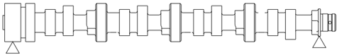
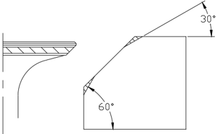
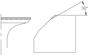
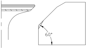
Dimensions
Outline Dimension (D/T model)
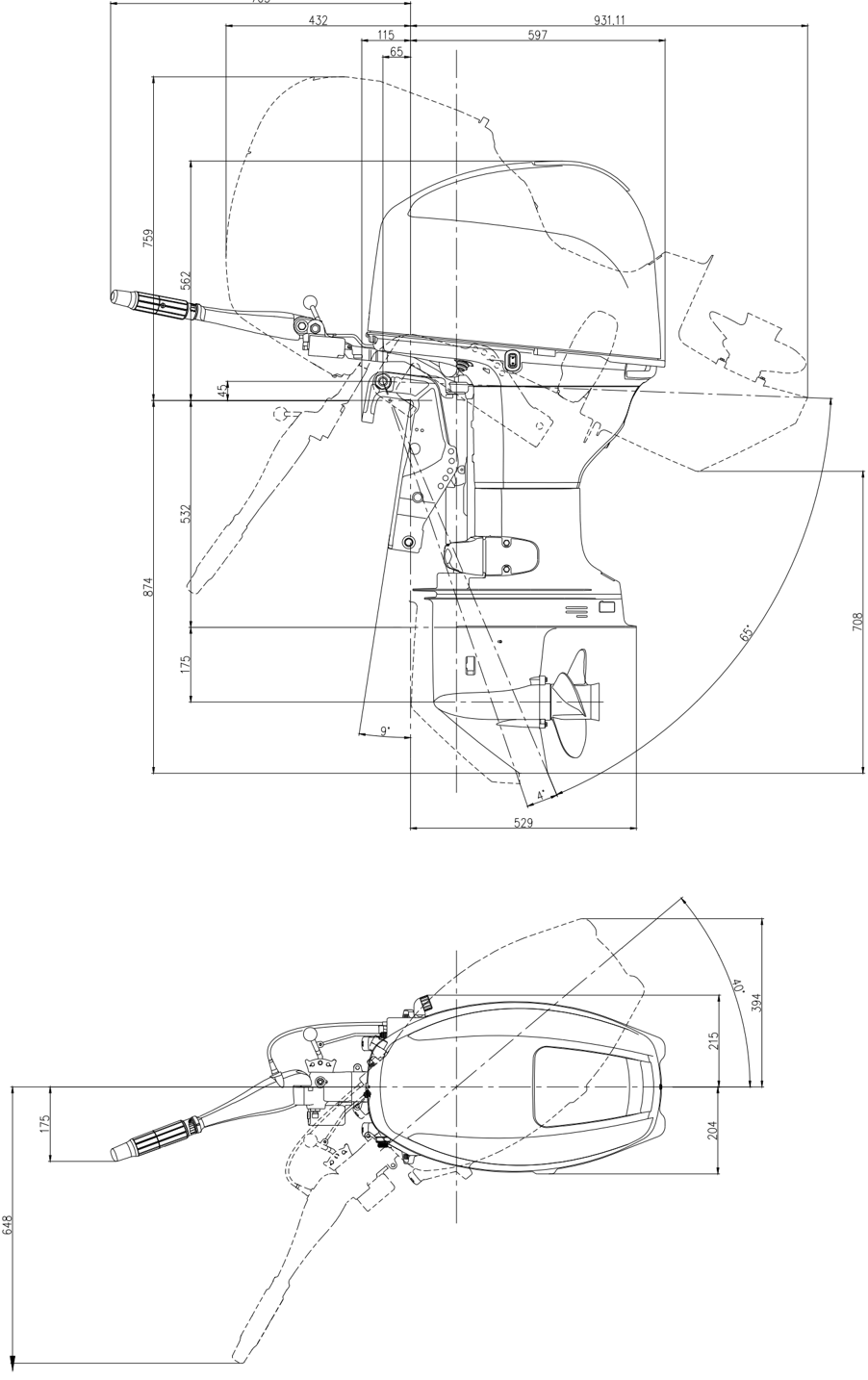
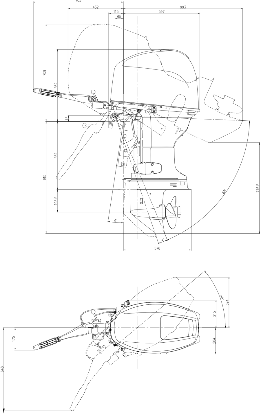
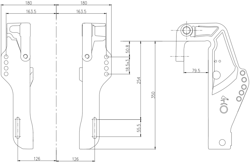
Mounting dimensions of clamp bracket
Basic Maintenance
Maintenance Interval Chart
| Initial maintenance | Initial maintenance | General maintenance interval | General maintenance interval | ||
|---|---|---|---|---|---|
| Item | Content | 10 hours (1 month) | 50 hours (3 month) | 100 hours (6 month) | 200 hours (1 year) |
| Anode | Check/replace | ○ | ○ | ||
| Anode (internal) | Check/replace | ○ | |||
| Cooling water channel | Clean | ○ | ○ | ||
| Spark plug | Clean/adjust/replace | ○ | ○ | ||
| Grease filling point | Add grease | ○ | |||
| Fuel filter | Check/replace | ○ | ○ | ○ | |
| Fuel system | Check | ○ | ○ | ○ | |
| Fuel tank | Check/clean | ○ | |||
| Idle speed | Check/adjust | ○ | ○ | ||
| Engine oil | Replace | ○ | ○ | ||
| Oil filter | Replace | ○ | |||
| Valve clearance (OHC) | Check/adjust | ○ | ○ | ||
| Ignition timing | Check | ○ | ○ | ||
| Thermostat | Check | ○ | |||
| Gear oil | Replace | ○ | ○ | ||
| Water pump | Check | ○ | |||
| Propeller and cotter pin | Check/replace | ○ | ○ | ||
| Timing band | Check/replace | ○ | ○ | ||
| Throttle cable | Check/adjust | ○ | |||
| Shift lever/shift cable | Check/adjust | ○ |
Attention:
Flush the outboard motor with fresh water immediately after operation in brine, sewage or muddy water.
If leaded petrol is frequently used, check valve and related parts every 100 hours.
Replace the timing band every 1000 hours (5 years).
Fuel System
- Check the fuel tank, fuel pump and fuel pipe.
Check the fuel tank, fuel pump and fuel pipe for leaks or damage and replace it if necessary.
Check the fuel oil filter core on the oil tank for any dirt, and clean or replace it if necessary.
- Check the fuel joint.
Check the fuel joint for cracks, leaks or damage. Replace it if necessary.
- Check the fuel filter.
Check whether the fuel filter is cracked or damaged, and check whether there is any dirt in the fuel filter.
If yes, replace the fuel filter.
Attention:
Wipe up the spilled fuel.
Attention:
Turn off the engine after running it and let it stand for several minutes. Check the oil level again with the oil dipstick.
If the oil level is not within the specified range, add/drain oil to the specified value.
Replace Engine Oil
- Remove the oil cap, oil drain bolt and bolt gasket; Drain the oil out.
- Install a new bolt pad and install the oil drain bolt.
- Add engine oil through the oil port.
- Install oil filter cap.
- Check oil level.
Engine oil level: 2.0 L (The oil filter is not replaced)
2.2 L (oil filter is changed)
Oil type: API SE, SF, SG, SH, SJ or SAE: 10W30, 10W40
Engine
Engine Oil Level
- Remove the oil dipstick and check whether the oil level is between the upper and lower marks of the oil dipstick.
- Drain the oil if it is above the high position mark, and add oil if it is below the low position mark.
- Oil dipstick 2. High position mark 3. Low position mark
Valve Clearance
- Remove the engine stop safety cable from the emergency stop switch assembly and remove the spark plug cap from the spark plug.
- Remove belt cover.
- Remove the fuel pump and cylinder head cover.
- Check the timing band for slack, aging, or damage. Replace it if necessary.
- Turn the flywheel clockwise. Align "1" on the driven pulley with "▼" on the cylinder head.
Check the intake valve clearance of cylinder 1# and 2# and the exhaust valve clearance of cylinder 1# and 3#. Correct it if necessary.
- Turn the flywheel 180° clockwise; Align "●" on the driven pulley with "▼" on the cylinder head.
- Check the intake valve clearance of cylinder 3# and 4# and the exhaust valve clearance of cylinder 2# and 4#. Correct it if necessary.
Attention:
It is strictly prohibited to turn the flywheel counterclockwise to avoid damage to the valve system.
Note:
Adjust valve clearance when the engine is cold.
| Valve clearance (Cold state) | Intake valve | 0.15~0.25mm |
|---|---|---|
| Exhaust valve | 0.25~0.35mm |
- Loosen the lock nut and turn the adjusting screw until the specified valve clearance is reached.
Note:
Turn the adjusting screw clockwise to reduce the valve clearance.
Turn the adjusting screw counterclockwise to increase the valve clearance.
- Reinstall the removed parts.
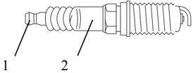
Spark Plug
- Remove the spark plug cap and then remove the spark plug.
- Remove carbon deposits from the spark plug electrodes.
- Check whether the electrodes are corroded, whether there is deposit, and whether the gasket is damaged. Replace the spark plugs if necessary.
Spark plug model: DPR7EA-9
- Check whether the electrode gap meets the specified value; Replace the spark plugs if necessary.
- Install the spark plug and tighten it with a spark plug wrench according to the specified torque.
Specified torque: 18 Nm
Control System
Throttle Cable
- Place the throttle grip in the closed position; Put the shift lever to the neutral position for the front operation model.
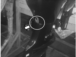
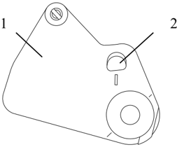
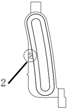
- Check whether the roller on the driven pulley of the throttle actuator can be observed in the observation window on the driving pulley of the throttle actuator; If the roller cannot be observed, adjust the length of the cable joint.
- Driving pulley of throttle actuator; 2. Observation window.
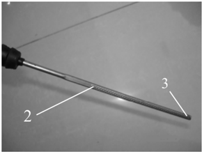
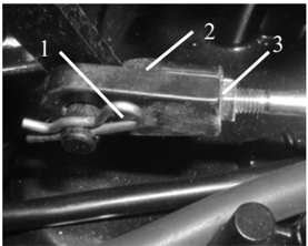
- Remove the cotter pin, remove the cable connector and loosen the lock nut of the cable joint.
- 4.Adjust the screw-in depth of the joint so that the joint hole is aligned with the pin of the throttle actuator driving pulley.
- Cotter pin 2. Cable joint 3. Lock nut
Attention:
Cable joints must be screwed in more than 8mm.
- 5.Fit the cotter pin and screw the lock nut.
Shift Operation
- Check whether the gear shifting operation is smooth;
- Place the shift lever in neutral position.
- Observe that the pin on the swing rod is aligned with the mark on the swing rod seat of throttle.
- If the pin is not aligned with the mark, adjust the screw-in depth of the cable joint. (Refer to the adjustment method of cable joint of throttle)
- Swing rod seat of throttle; 2. Mark.
Note:
Check the drained gear oil. If gear oil is emulsified, check the seal and replace it if necessary. If there are metal debris in the gear oil, check the gears and bearings.
Attention:
A new drain screw gasket must be replaced every time .
Air tightness Inspection of Lower casing Unit
Connect the leak detection device to the oil level plug hole to check the air tightness of the Lower casing unit. If the pressure drops (the pressure is 1kg/cm 3 ), check the oil seal and other components.
General maintenance
Anode
Check the anodes of the Lower casing unit and the engine (installed on the thermostat cover); Remove oil and scale; If damage or corrosion exceeds 1/2, replace the anode.
Attention:
Do not apply oil or paint to the anode to avoid failure of the anode.
Check gear oil level
Remove the oil level plug screw. If there is oil spill, the oil level is correct. If there is no oil spill, add oil to it.
- Oil level plug screw
Change gear oil
- Place the outboard motor upright.
- Place a container with sufficient capacity under the outboard motor.
- Remove the oil drain screw, and then remove the oil level plug screw to drain the gear oil.
- Inject gear oil into the oil drain screw hole using the pressure filling device.
- When gear oil spills out of the oil level plug hole, install the oil level plug screw.
- Install the oil drain screw; Wipe off the spilled gear oil.
- Oil level plug screw 2. Oil drain screw
Lower Casing Unit
Gear Oil
Lubrication Point
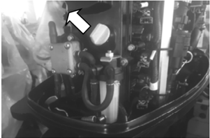
- Fill or apply waterproof grease to the parts shown in the figure with an oil gun.
- Apply anti-corrosion lubricating oil to the propeller shaft.
Cooling Water Channel
- Check the inlet of the cooling water channel for blockage. Clean it if necessary.
- Place the outboard motor in the water to ensure that the water level is above the anti-swirl plate and start the engine.
- Check whether there is cooling water flowing out from the observation hole. If there is no water or the water flow is intermittent, check the cooling water channel in the outboard motor.
- Cooling water observation hole
- Thermostat
- Remove the thermostat cover, and then remove the thermostat.
- Inlet of cooling water channel
- Hang the thermostat in a container with water.
- Heat the container.
- Check the opening of thermostat valve at the specified water temperature; If it does not conform to the specifications, replace it.
- Install the thermostat and thermostat cover and tighten the bolts to the specified values.
| Water temperature | Opening height of valve |
|---|---|
| Below 60℃ | Not open |
| Above 70℃ | More than 3mm |
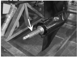
Propeller
Inspect the propeller blades and internal splines for rupture, damage or wear. Replace it if necessary.
Electrical System
Attention:
Please be careful when monitoring and repairing the ignition system Do not place your hands, clothes, hair or accessories close to the running flywheel.
Test the ignition coil on an insulated workbench to prevent electric leakage and electric shock. When the engine is running, do not touch the ignition coil or spark plug to avoid electric shock. Make sure that the wire is away from the running flywheel to prevent the wire from being cut off or the wire insulation from being worn.
When replacing fasteners (nuts and bolts), pelase use the parts provided by the manufacturer or of the same material and strength and tighten them with specified torque.
Front-operation electrical starting
Spark Plug Ignition
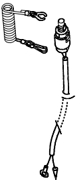
- Remove the spark plug cap from the spark plug.
- Connect the ignition detector to the spark plug cap.
- Start the engine and observe the spark through the discharge window of the detector.
- Spark plug cap; 2. Spark plug
Do not touch any joint of the detector lead.
Warning:
Stay away from combustible gases or liquids to avoid accidents caused by spark ignition.
Spark Plug Cap
- Unscrew spark plug cap. Check the spark plug cap for damage. Replace it if necessary.
- Install spark plug cap.
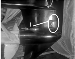
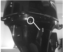
Flywheel Maintenance
- Remove the flywheel nut using the flywheel gripper; Remove the flywheel using the flywheel puller.
- Check whether the flywheel is damaged and whether the permanent magnet is firm. Replace it if necessary.
Check the Ignition Coil
- Remove the ignition coil and the spark plug cap.
- Measure the resistance of the ignition coil. If the specified value is not met, replace it. Primary resistance: 2.2±0.22Ω Secondary resistance 9.84±0.98kΩ
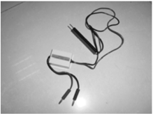
Check the trigger coil
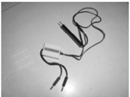
- Trigger coil peak voltage
Use a digital multimeter and a peak voltage adapter to measure the coil output peak voltage. If it is below the specified value, check the trigger coil resistance.
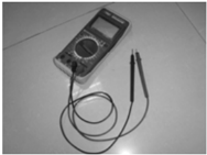
Digital multimeter Peak voltage adapter Pulse coil peak voltage: ≥13 V@1000 r/min (load)
- Trigger coil resistance
Measure coil resistance. If the specified value is not met, replace it.
Resistance: 260 ~ 290 (the positive electrode of the detector is connected with red/white line and the negative electrode is connected with black line)
Note:
The data are for reference only.
Check the Engine Start Switch
Check the conductivity of the engine start switch. If it is not conductive, replace it.
Note:
See wiring diagram for starting switch status table,
Check the Engine Stop Switch
Check the conductivity of the engine stop switch. If it is not conductive, replace it.
Remove locking plate: Conductive
Install locking plate: Not conductive
Press the button: Conductive
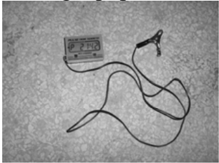
Check the Starting Relay
- Connect the brown lead to the positive electrode of the battery.
- Connect the black lead to the negative electrode of the battery.
- Check the conductivity between relay terminals. If it is not conductive, replace the relay.
- Disconnect the lead connection to the battery and check the conductivity between relay terminals. If it is conductive, replace the relay.
Check the Magneto Coil
Measure the peak voltage of the magneto coil (between the green lines).
Use a digital multimeter and a peak voltage adapter to measure the coil output peak voltage. If it is below the specified value, replace the magneto coil.
| Magneto coil peak voltage | 1500 r/min (no load) | 47.2V |
|---|---|---|
| 3500 r/min (no load) | 106V |
Check the Rectifier Regulator
Measure the rectifier regulator peak voltage (dc).
Open the circuit of rectifier output (red line and black line) and use a digital multimeter to measure the voltage between the red line and black line at the rectifier regulator output.
If it is below the specified value, check the magneto coil output peak voltage. If the peak output voltage of the magneto coil is higher than the specified value, replace the rectifier regulator.
| Rectifier regulator peak voltage | 1500 r/min (no load) | 41.9V |
|---|---|---|
| Rectifier regulator peak voltage | 3500 r/min (no load) | 99.8V |
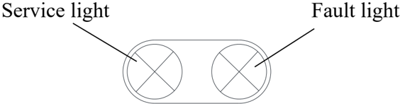
How to Use the Diagnostic Scan Tool
When the engine is running, if the fault light on the bottom cover is always on or the service light is always on/the buzzer is always ringing, it means that there is a fault in the engine. At this time, connect the scan tool with the corresponding detection port on the engine. Through the APP software downloaded in the mobile phone, the operating parameters and fault codes of the engine can be displayed on the mobile phone. Then check the fault code table to determine the fault of the engine and replace the faulty electrical components.
Fault Code Table
| Failure type | Failure item | Code |
|---|---|---|
| Intake pressure failure | Short circuit to ground or open circuit in intake pressure sensor line | 107 |
| Intake pressure failure | Short circuit to high level in intake pressure sensor line | 108 |
| Intake air temperature failure | Short circuit to high level in intake air temperature sensor line | 112 |
| Intake air temperature failure | Short circuit to ground or open circuit in intake air temperature sensor line | 113 |
| Water temperature failure | Short circuit to ground in coolant temperature sensor line | 117 |
| Water temperature failure | Short circuit to high level in coolant temperature sensor line | 118 |
| Throttle failure | Short circuit to ground in throttle position sensor line | 122 |
| Throttle failure | Short circuit to high level in throttle position sensor line | 123 |
| Oxygen sensor failure | Short circuit to ground in oxygen sensor | 131 |
| Oxygen sensor failure | Short circuit to high level in oxygen sensor | 132 |
| Oxygen sensor heating failure | Oxygen heater failure | 135 |
| Fuel injector failure | Nozzle line failure of cylinder 1 | 201 |
| Fuel injector failure | Nozzle line failure of cylinder 2 | 202 |
| Fuel injector failure | Nozzle line failure of cylinder 3 | 203 |
| Fuel injector failure | Nozzle line failure of cylinder 4 | 204 |
| Fuel pump failure | Oil pump relay failure | 230 |
| Crankshaft position sensor failure | Crankshaft position sensor line signal interference | 336 |
| Crankshaft position sensor failure | Crankshaft position sensor line no signal | 337 |
| Ignition coil failure | Ignition coil failure of cylinder 1 | 351 |
| Ignition coil failure | Ignition coil failure of cylinder 2 | 352 |
| Idle speed failure | Excessive idle speed | 507 |
| Idle speed failure | Low idle speed | 506 |
| System voltage failure | Low system voltage | 562 |
| System voltage failure | High system voltage | 563 |
| Fault light | Fault indicator lamp failure | 650 |
| Oil pressure failure | Short circuit to ground in oil pressure sensor line | 523 |
| Oil pressure failure | Short circuit to high level in oil pressure sensor line | 522 |
| Carbon canister solenoid valve failure | Short circuit to ground in carbon canister solenoid valve | 443 |
| Main relay failure | Main relay failure | 685 |
Attention:
Fuel is a highly flammable and volatile liquid. Fuel leakage can cause fire and explosion.
Do not attempt to start the engine before determining that the components of the fuel system are connected or installed. After completing all repair steps, apply pressure to the fuel system for a short period of time to check for leaks.
Fuel System
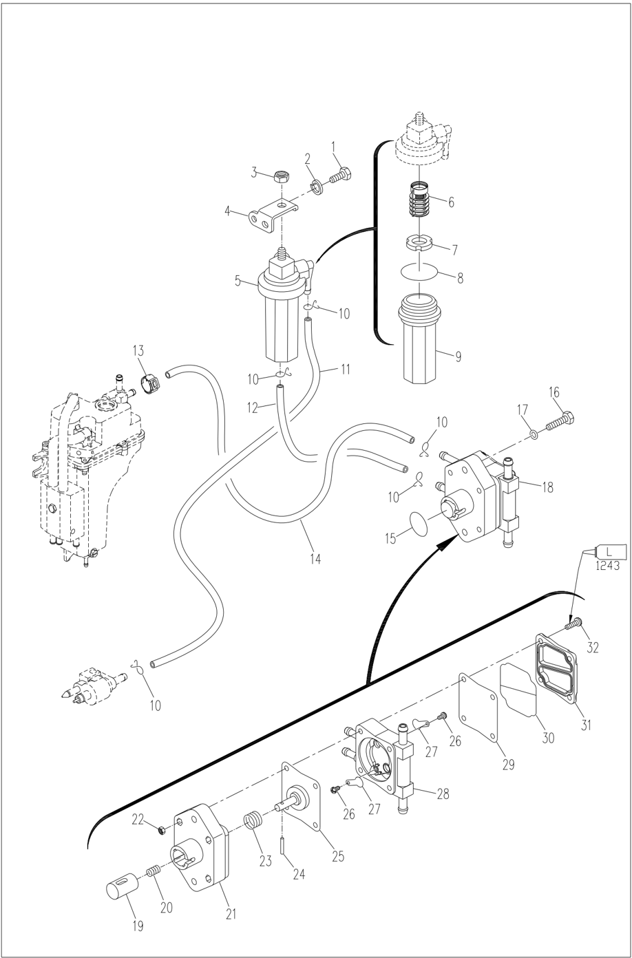
Relieve the Fuel Pressure in the Fuel Lines
Before carrying out maintenance and inspection of the fuel system, the fuel pressure in the fuel pipeline shall be released. Avoid accidents caused by high-pressure fuel injection during maintenance.
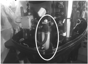
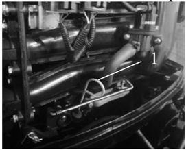
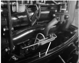
- Connect the pressure gauge with the pressure relief pipe to the oil pump check valve of the electric fuel pump;
- Fuel pump check valve.
- Insert the pressure relief pipe into a suitable container;
Attention:
Do not release the pressure directly, and the fuel will be discharged while the pressure is released. Fuel spraying can cause accidents and violate local emission regulations.
- Press the pressure release button to release the pressure until the pressure inside the electric fuel pump is balanced with the outside world.
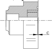
Remove and Check the Fuel Joint
- Remove the bolt securing the fuel joint.
- Remove fuel joint.
- Check the fuel joint for cracks, leaks or damage.
- Connect the outlet of the fuel joint to the vacuummanometer.
- Detect whether the negative pressure can be maintained for more than 10 seconds under the specified pressure. Replace it if necessary. Specified pressure: 50kPa
Remove and Check the Fuel Pump
- Remove the bolt securing the fuel pump.
- Remove the fuel pump.
- Connect a vacuummanometer to the inlet of the fuel pump.
- Block the outlet of the oil pump with your fingers and apply the specified positive pressure. Check for air leaks. Specified pressure: 50kPa
- Apply a prescribed negative pressure. Check for air leaks. Specified pressure: 30kPa
- Connect a vacuummanometer to the outlet of the fuel pump.
- Block the inlet of the oil pump with your fingers and apply the specified negative pressure. Check for air leaks. If necessary, disassemble the oil pump and check it. Specified pressure: 50kPa
- Remove the 4 bolts and separate the fuel pump cover from the fuel pump seat.
- Remove the valve plate screw from the fuel pump body and remove the valve plate.
- Press the plunger and diaphragm, rotate the fuel pump seat and align the notch with the groove on the plunger. Remove needle roller.
- Check whether there are cracks on the diaphragm, whether the riveting is loose, and whether the valve plate is damaged. Replace it if necessary.
- Follow steps 8-10 in reverse sequence and assemble the oil pump.
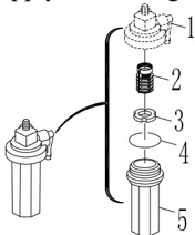
Check the Fuel Filter
Check whether the filter screen of the filter is blocked or there are sundries, and check whether the filter cup is damaged or leaked.
If necessary, clean with gasoline or replace the filter screen.
Note:
Apply lubricating oil to the O-ring before reassembling the filter cup.
- Filter cup lid
- Filter screen
- Float
- O-ring
- Filter cup
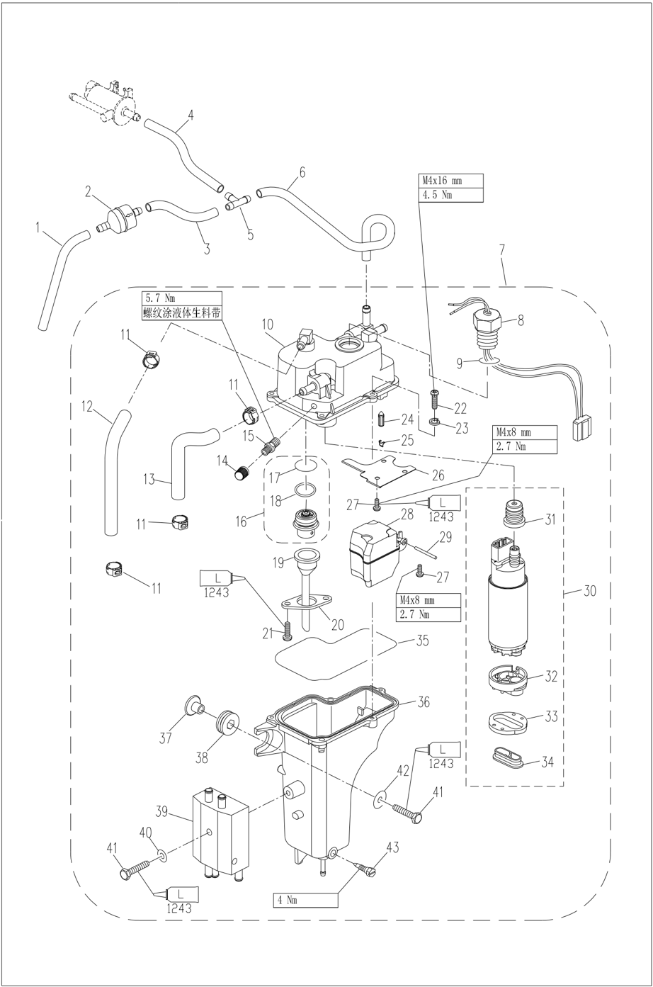
Remove and Check the Electric Fuel Pump
Disassembly of Electric Fuel Pump
- Loosen the oil drain screw of the oil cup and drain the fuel in the oil cup into a suitable container.
- Remove fuel line and cooling water line and disconnect the wiring harness connection.
- Remove the mounting screws of the electric fuel pump and remove the electric fuel pump from the engine.
- Disconnect the line connection between the fuel cooler and the electric fuel pump and remove the fuel cooler.
- Remove the 5 cross-recessed pan-head screws (M4×16) and remove the electric fuel pump body assembly.
- Pull off the oil pump assembly and disconnect the oil pump connector assembly;
- Check and clean the oil pump filter screen on the oil pump assembly;
- Check the rubber sleeve at the oil pump nozzle and replace it if it is aged, damaged or cracked.
- Loosen the screw fixing the float pin and remove the float;
- Remove the baffle; (if necessary)
- Check and clean the oil cup assembly of the electric fuel pump;
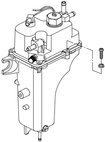
- Loosen the fixing screw of the pressure valve pressure plate and remove the pressure regulating valve;
- Check the O-ring of the pressure regulating valve; Replace it if necessary;
- After the check, clean the parts and install the electric fuel pump in the reverse order. Attention: A new oil cup sealing ring is required; The screws shall be tightened to the specified torque!
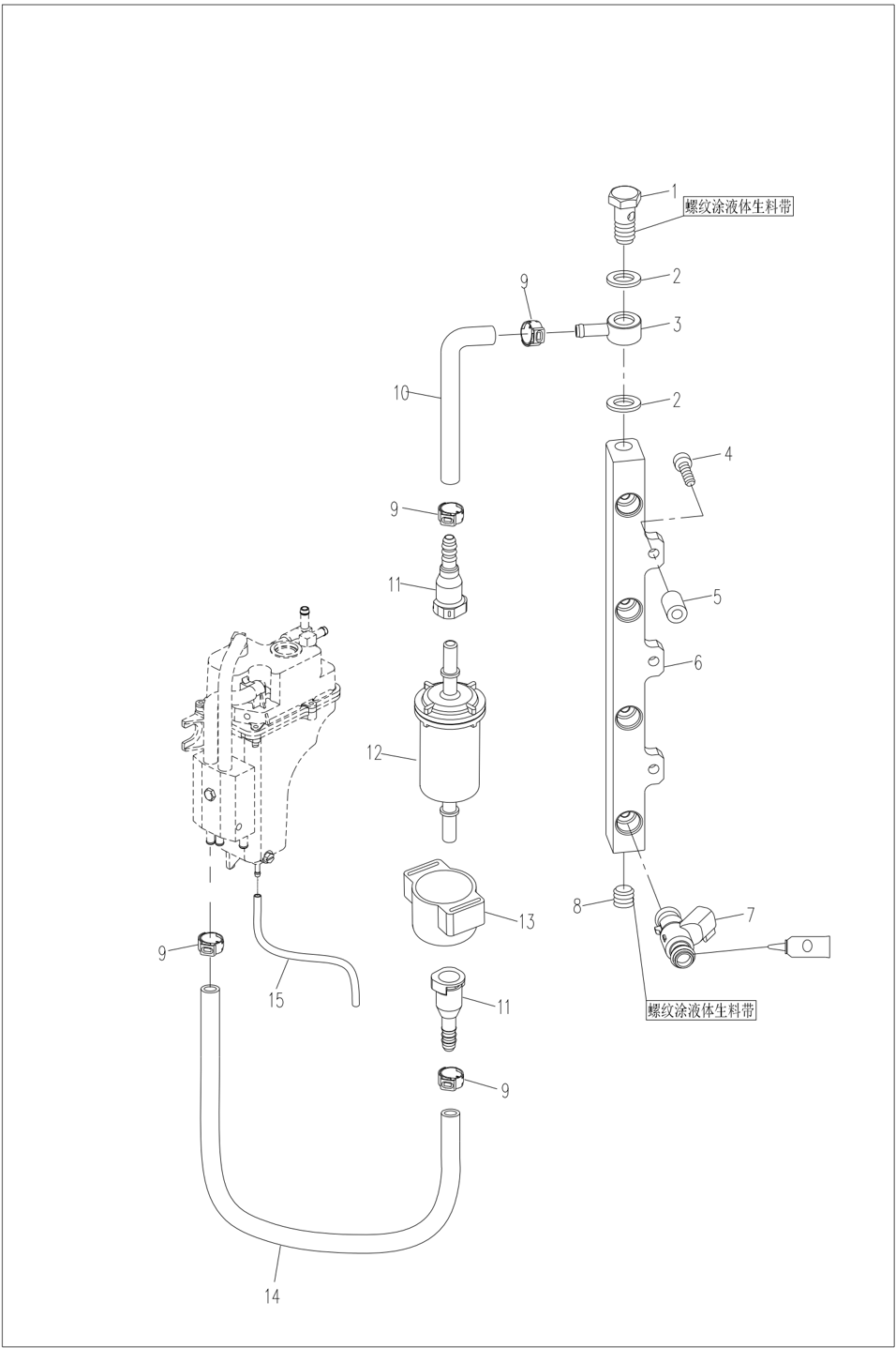
Check the Fuel Pipe and Fuel Filter
- Check the fuel pipe for damage.
- Check whether the high-pressure fuel filter is cracked and whether the fuel flows smoothly. Replace it if necessary.
Check the Fuel Common Rail
Check the fuel common rail for leaks or cracks and damage, and replace it if necessary.
Engine
Attention:
In order to avoid accidental starting when repairing the engine, adequate protective measures should be taken to disconnect the ignition system. For example:
Remove the engine stop safety cable from the emergency stop switch assembly and remove the spark plug cap from the spark plug.
Note:
If the cylinder pressure continues to increase, check the piston and piston ring for damage. Replace it if necessary.
If the cylinder pressure does not increase, check the valve clearance, valve, valve seat, cylinder liner, cylinder head and cylinder head gasket.
Adjust or replace it if necessary.
The outboard motor is equipped with automatic pressure relief device, and the data cannot be very accurate.
Check the Oil Pressure
- Start the engine, warm it up for 5 minutes, then shut it down.
- Remove oil pressure switch and connect pressure gauge.
Note:
Use a manometer with a 1/8 pitch thread adapter.
Special Tools
Piston slideway Flywheel gripper Valve spring compressor kit
Clearance gauge Oil filter spanner
and flywheel puller
Check the Compression Pressure
- Start the engine, warm it up for 5 minutes, then shut it down.
- Remove engine stop safety line.
- Remove the spark plug and connect the pressure gauge to the spark plug hole.
Attention:
Before removing the spark plug, clean the pit where the spark plug is installed with compressed air to prevent dust or other sundries from entering the cylinder.
- Fully open the throttle, turn the crankshaft with the starter or starting motor, and check the cylinder pressure when the reading on the pressure gauge is stable.
Note:
For models using the control box, remove the throttle linkage, fully open the carburetor throttle lever by hand, and then detect the pressure.
Compression pressure: 840 kPa
- Check oil pressure Oil pressure (reference data): 100kpa (800±50 r/min)
Disassemble the Engine
- Open the top cover.
- Remove the flywheel cover.
- Remove the throttle cable.
- Remove the carburetor.
- Remove the flywheel with special tools.
- Remove the semicircle key.
- Disconnect the engine stop switch line and the ground wire.
- Remove the cable joint.
- Remove the magneto coil.
- Disconnect the wires of electrical components such as storage battery, starting motor, starting relay, tilting relay and control box connector, Disconnect the ground wire and the water pipe.
- Remove the ignition coil, ECU device, ignition coil and spark plug.
- Remove the bolts connecting the engine to the water unit.
- Lift the engine and remove the locating pin.
Flywheel gripper and flywheel puller
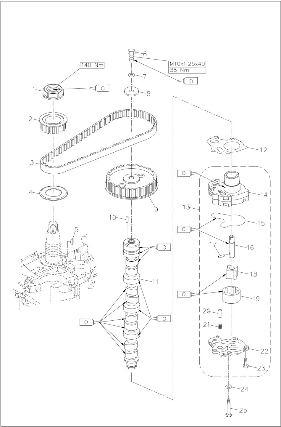
Pulley and Timing Belt
- Turn the flywheel clockwise. Align "1" on the driven pulley with "▼" on the cylinder head.
Attention:
Do not turn the flywheel counterclockwise, otherwise the valve system will be damaged.
- Remove timing belt from the driven pulley side.
Attention:
When the timing belt is not installed, do not turn the pulley, otherwise the valve system will be damaged.
- Remove the driven pulley bolt, remove the driven pulley and the semicircular key.
Note:
Remove the driven pulley bolt with the flywheel gripper.
Do not turn the camshafts when loosening the timing pulley.
Note:
Before removing the rocker shaft, loosen the lock nut and adjust the screw to the relaxed state.
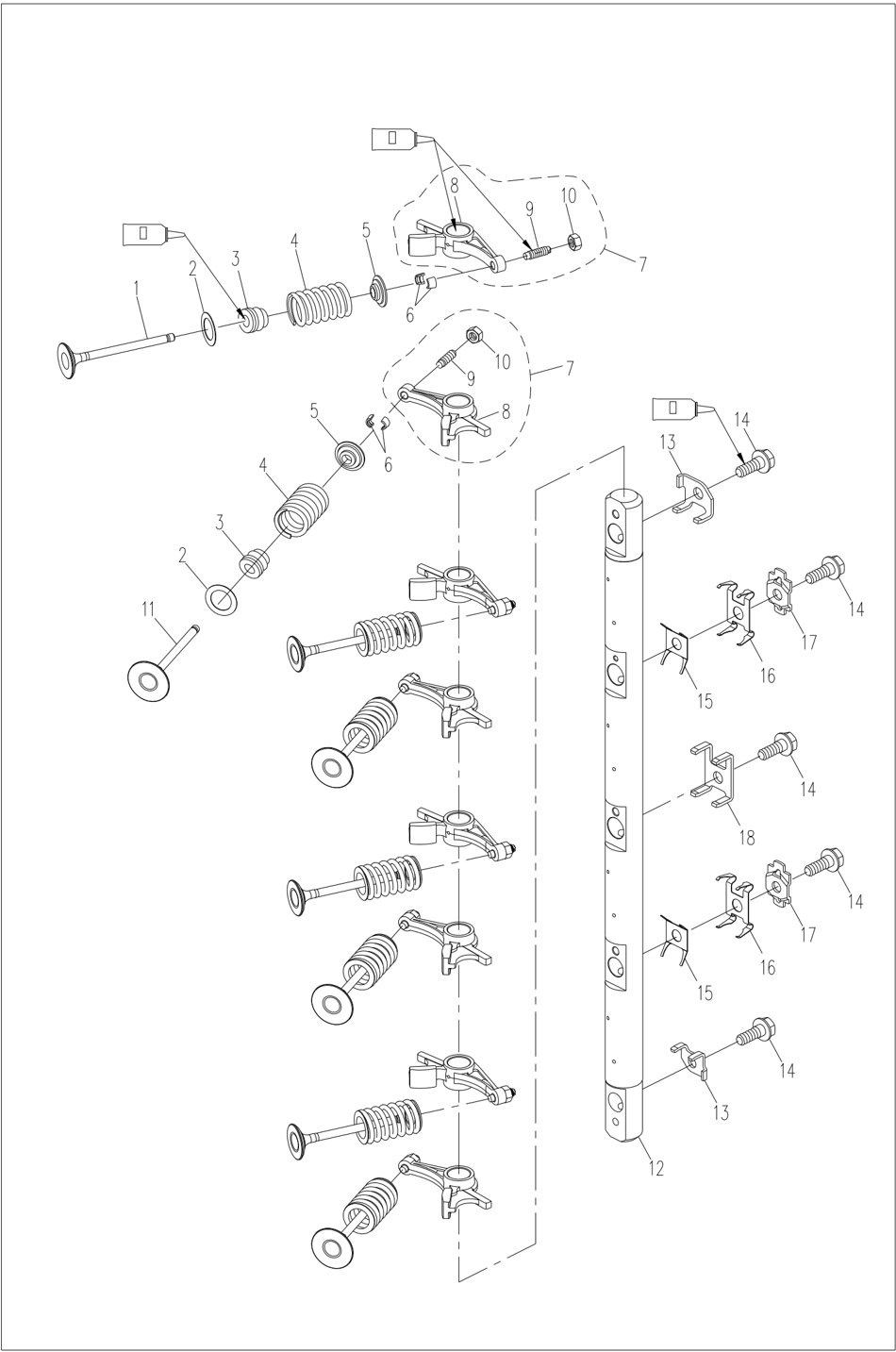
- Remove intake and exhaust valve using the valve spring compressor.
Valve and valve guides
- Remove the timing pulley washer, timing pulley and semicircular key.
- Check the pulley and timing belt for cracks, damage or wear. Replace it if necessary.
- Install the semicircular key and the driven pulley.
Align "1" on the driven pulley with "▼" on the cylinder head. Then temporarily tighten the driven pulley bolts.
Attention:
When the timing belt is not installed, do not turn the pulley, otherwise the valve system will be damaged.
- Install the semicircular key and timing pulley. Align the notch mark on the timing pulley with the mark "▼" on the body.
- Install the new timing belt with the part number of the timing belt upright.
Attention:
Do not twist, rotate or bend the timing belt, otherwise the timing belt will be damaged.
Do not put oil or lubricating oil on the timing belt.
Do not turn the pulley counterclockwise, otherwise the valve system will be damaged.
- Install the timing pulley cover plate and temporarily tighten the timing pulley nut.
- Turn the timing pulley clockwise for 2 turns to eliminate the slackness of the timing belt.
Check if the alignment marks are aligned.
- Tighten the bolts and nuts.
Locking torque: Driven pulley bolt 38 Nm
Note:
Remove the driven pulley bolt with the flywheel gripper.
Tighten timing pulley nuts with a special socket wrench for timing pulley nuts.
Disassembling and Check
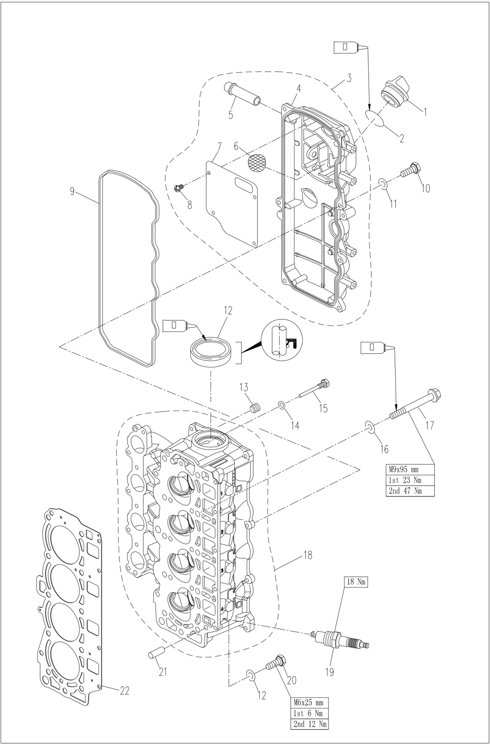
Cylinder Head
Disassembling
- Remove cylinder head cover bolts.
- Remove the cylinder head bolts in reverse order according to the numeric markings on the cylinder head.
- Remove the cylinder head and then remove the oil pump.
- Remove the rocker shaft, spring and rocker assembly.
- Check the width of the valve sealing surface if it is not within the specified scope. Trim the valve seat ring.
Width of sealing surface:
| Intake valve | 1.84 ~ 2.97mm |
|---|---|
| Exhaust valve | 1.98 ~ 3.11mm |
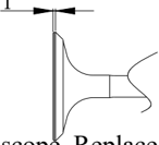
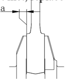
- Check the valve edge thickness T; If the specified value is not met, replace the valve. Valve edge thickness: T
- Check valve stem diameter. If it is not within the specified scope. Replace the valve. Valve stem diameter.
- Check the roundness of the valve stem. If it exceeds the limit, replace the valve. Valve stem roundness limit 0.03mm
- Check the inner diameter of the valve guide. Inner diameter of the valve guide. 5.50 ~ 5.51 mm
| Intake valve | 0.6 ~ 1.0mm |
|---|---|
| Exhaust valve | 0.7 ~ 1.1mm |
| Intake valve | 5.48 ~ 5.49mm |
|---|---|
| Exhaust valve | 5.46 ~ 5.47mm |
Attention:
When replacing valve, be sure to use new valve guides and valve seal.
Valve spring
- Check the free length of the valve spring; If it is less than the specified value, replace it. Free length: 39.85 mm
- Check the inclination of the valve spring; If it exceeds the limit, replace the valve.
Min. free length: 37.85 mm
Inclination limit: 1.7 mm
Valve rocker and rocker shaft
- Check the contact surface of the valve rocker and rocker shaft for wear. Replace it if necessary.
- Measure whether the inner diameter of the valve rocker and the outer diameter of the rocker shaft conform to the specified values. Replace it if necessary. Inner diameter of the valve rocker: 16.000 ~ 16.01 mm
Outer diameter of rocker shaft: 15.97
~ 15.99 mm
Camshaft
- Check cam size.
Replace the camshaft if necessary.
| Height of cam | Intake | 30.89~30.99mm |
|---|---|---|
| Height of cam | Exhaust | 30.82~30.92mm |
| Diameter of base circle | Diameter of base circle | 25.95~26.05mm |
- Check camshaft roundness. Replace it if necessary. Roundness limit : 0.03mm
Note:
Apply oil to the surface of the guide before installation.
- Hinge the inner diameter of the conduit to the specified value with a reamer. Inner diameter of the valve guide. 5.50 ~ 5.51 mm
Note:
Do not rotate the reamer counterclockwise when taking it out.
Check the valve seat ring.
- Remove carbon deposits from the valve.
- Apply a thin layer of dye evenly to the sealing surface of the valve seat ring.
- Grind the valve on the valve seat with a valve grinding tool.
- Measure the width of the valve sealing surface.
Dye will stick to the valve sealing surface.
If the valve and valve seat ring are not properly matched or the width of the sealing surface does not conform to the specified value, trim the valve seat.
- Check camshaft journal diameter and cylinder head shaft hole inner diameter. Replace it if necessary.
Camshaft journal top diameter a1 (driven pulley mounting end): 36.9336.94 mm Camshaft journal centre and rear diametera2: 36.9436.95 mm Cylinder head shaft hole inner diameter b: 37.00~37.02 mm
- Calculate camshaft oil clearance c (c=b-a), If the specified value is not met, replace it. Top of camshaft: 0.06~0.10 mm
Centre and rear of camshaft: 0.05~0.09 mm
Attention:
The camshaft and cylinder head need to be replaced together.
Check the oil pump
- Remove the screws securing the oil pump and remove the oil pump.
- Open the oil pump cover and check the oil pump rotor clearance as shown If the specified value is not met, replace it. a
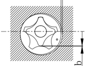
| Clearance between outer rotor and casing a | 0.09~0.15mm |
|---|---|
| Clearance between outer rotor and inner rotor b | 0.01~0.10mm |
| Clearance between rotor and cover c | 0.03~0.08mm |
Joint surface of cylinder head and body
- Remove carbon deposits from the combustion chamber and check for damage.
- Use a ruler and gap gauge to check the bending of the joint surface. If the specified value is not met, replace it.
Cylinder head bending limit: 0.03 mm
Replace valve guide
- Knock off the valve guide from the direction of the combustion chamber.
- Knock in a new valve guide from the top surface of the cylinder head.
If the contact is uneven, replace the valve guide. Width of inlet and exhaust valve sealing surface: 0.9 ~ 1.1mm
Trim the valve seat ring
- Trim the valve with a 45° valve seat ring cutter and adjust the width of the sealing surface.
Turn the cutter clockwise until the surface of the seat ring is smooth.
- If the valve sealing surface is too wide and in the middle of the valve surface, trim the top edge of the seat ring with a 30° cutter and the bottom edge of the seat ring with a 60° cutter and adjust the width of the sealing surface.
- If the valve sealing surface is too narrow and at the top edge of the valve surface, trim the top edge of the seat ring with a 30° cutter, if so, adjust the width of the sealing surface with a 45° cutter.
- If the valve sealing surface is too narrow and at the bottom edge of the valve surface, trim the bottom edge of the seat ring with a 60° cutter, and if so, adjust the width of the sealing surface with a 45° cutter.
- Apply a thin layer of abrasive evenly on the valve seat ring and grind the valve with a valve grinding tool.
- Remove the residual abrasive.
- Check the valve sealing surface width again.
Attention:
Don't cut the valve too much, turn the cutter evenly with a downward force of 40 ~ 50N. Do not attach the abrasive to the valve stem and valve guide.
Note:
Ensure that the mark on the outer rotor face the oil pump cover
- Fit oil pump by aligning oil pump drive shaft and camshaft pin.
Attention:
Before installing the oil pump, make sure that the oil circuit is smooth and fill the oil pump with oil.
Install valve
- Install a new valve oil seal and coat the valve guide with engine oil.
- Install the valve, valve spring pad, valve spring and spring seat in sequence.
- Compress the valve spring with a valve spring compressor and install the valve spring retainer.
- Tap the valve spring seat lightly with a plastic or rubber hammer to secure the retainer.
Assemble cylinder head
- Install the new oil seal with special tools.
- Fit the camshaft into the cylinder head from the direction of the oil pump.
- Check that the camshaft head locating pin hole is positioned in the direction of the cylinder head cover (rocker side). If necessary, make adjustments.
- Install the rocker assembly, spring and rocker shaft.
- Assemble the oil pump.
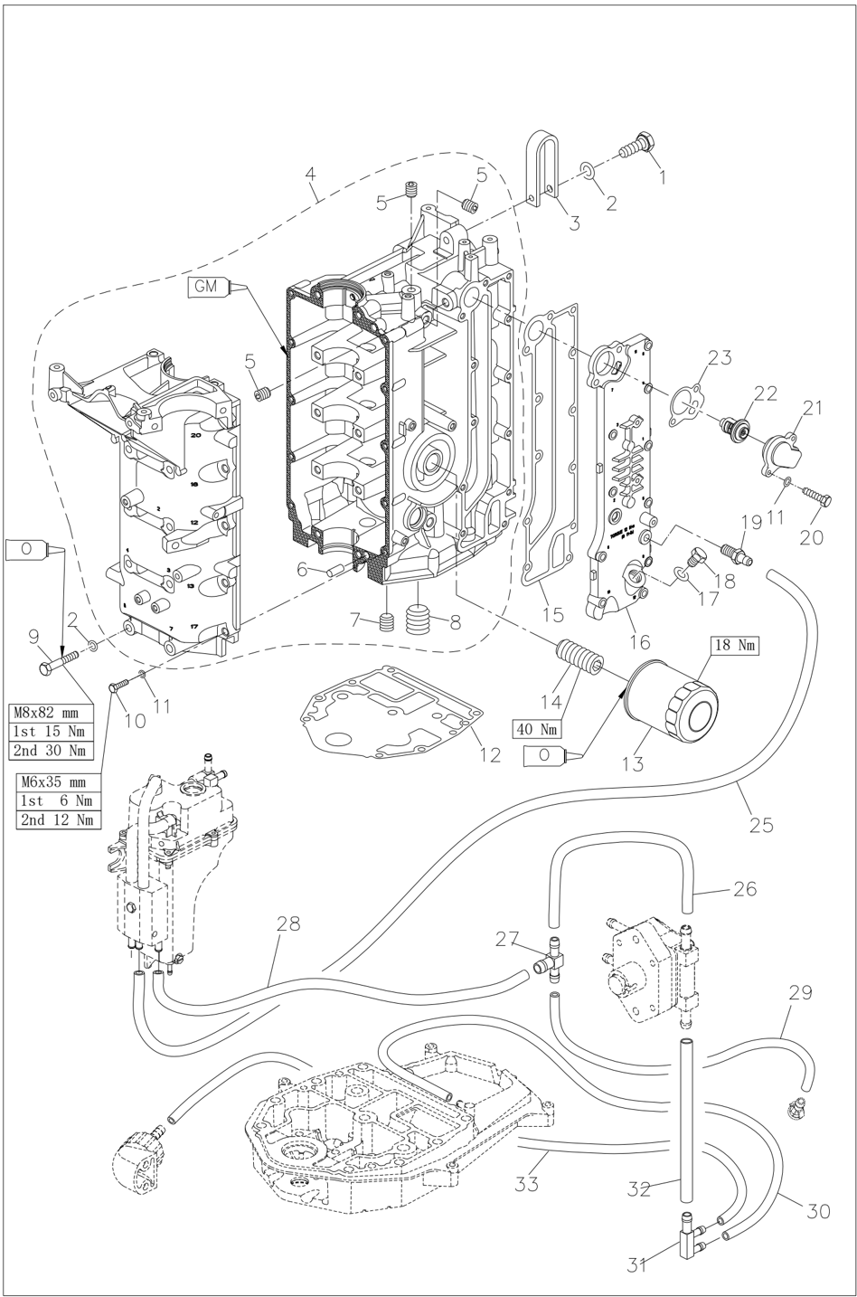
Crankcase
Disassembling
- Remove the oil filter with special tools.
Note:
Put a cloth under the oil filter.
Filter wrench
- Remove the bolts in reverse order according to the serial number on the edge of the screw hole on the exhaust cover plate.
- Remove thermostat cover, exhaust cover, gasket and locating pin.
Clean the anode surface, check the anode, and replace the anode if the corrosion exceeds half of the surface.
Check the exhaust cover plate for cracks, deformation or corrosion. Replace it if necessary.
- Remove the box bolts in reverse order according to the serial number on the edge fo the screw hole of the engine base, and remove the engine base.
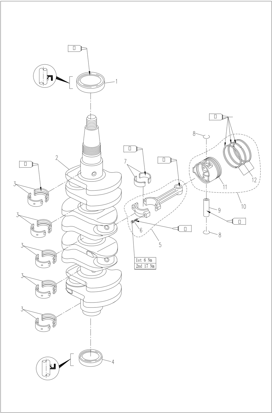
- Remove the connecting rod bolt and connecting rod cover, remove the crankshaft, and then remove the connecting rod and piston assembly.
- Remove the piston pin circlip with pliers, then remove the piston pin and the piston.
- Remove the oil seal, locating pin and bearing bush.
Piston
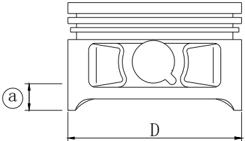
- Measure the piston outer diameter at the specified measuring point.
If the specified value is not met, replace it.
Diameter of piston: 64.950
~ 64.965 mm
Measuring point○
a : 5mm
- Check the inner diameter of piston pin bore.
If the specified value is not met, replace it.
Inner diameter of piston pin bore: 15.974~15.985mm
Cylinder bore
- Measure the piston outer diameter ○ 1 , ○ 2 and ○ 3 at the specified measuring point. At each measure point, six diameters parallel to the crankshaft direction D1, D3, D5 and perpendicular to the crankshaft direction D2, D4, D6 are measure respectively.
- Calculate the taper limit and roundness limit. If the specified value is exceeded, replace the crankcase.
Height of measuring point ○ 1 20 mm;
○ 260 mm;
○ 3100 mm
Cylinder bore: 65.000
~ 65.013 mm
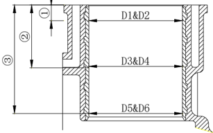
taper limit: 0.08 mm (D1-D5, D2-D6)
Roundness limit :
0.05 mm (D2-D1, D6-D5)
Piston pin outer diameter
Check the piston pin outer diameter; If it does not conform to the specified value, replace it.
Piston pin outer diameter: 15.965
~ 15.970 mm
Piston ring
- Check the piston ring cross-sectional dimensions. If the specified value is not met, replace it.
- Push the piston ring parallel into the cylinder with the piston to the specified measuring point (20mm from the joint surface).
- Measure the end clearance of piston ring with clearance gauge; If it does not conform to the specified value, replace it.
| Thickness | Section width | |
|---|---|---|
| Top ring | 1.17 ~ 1.19mm | 2.39 ~ 2.41mm |
| 2 nd ring | 1.47~1.49mm | 2.49 ~ 2.51mm |
| Oil ring | 2.34 ~ 2.46mm | 2.75mm |
End clearance (when installing) Top ring 0.15 ~ 0.30 mm
2 nd
ring 0.30 ~ 0.50 mm
Oil ring 0.20 ~ 0.70 mm
- Install the piston ring on the piston and measure the clearance between the piston ring and the piston ring groove with clearance gauge. If it does not conform to the specified value, replace it.
Specified clearance: Top ring 0.02 ~ 0.06 mm
2 nd
ring 0.02 ~ 0.06 mm
Oil ring 0.04 ~ 0.18 mm
Inner diameter of connecting rod small end Measure the inner diameter of small end. If the specified value is not met, replace it.
Inner diameter of small end: 15.985
~ 15.998 mm
Connecting rod big-end backlash
Measure big-end backlash.If the specified value is not met, replace the connecting rod or crankshaft or both. a
Big-end backlash: 0.05
~ 0.22 mm
Check the connecting rod bolts
- Check the thread diameter of the connecting rod bolt at the position shown.
- Calculate the difference between the diameters of the two threads; If it does not conform to the specified value, replace it.
Diameter difference of connecting rod bolt threads: 0 ~ 0.1 mm
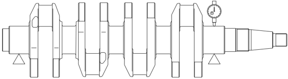
Crankshaft
- Measure the crankshaft journal diameter, crank pin diameter and crank pin width. If the specified value is not met, replace the crankshaft.
- Check crankshaft runout; If the specified value is exceeded, replace it.
| Crankshaft journal diameter | 42.984~43.000mm |
|---|---|
| Crank pin diameter | 32.984~33.000mm |
| Crank pin width | 21.000~21.070mm |
Crankshaft runout limit: 0.04mm
Clearance between crank pin and oil
- Place a plastic clearance gauge on the crank pin and make it parallel to the crankshaft.
- Fit the connecting rod and bearing bush on the crank pin.
- Tighten the connecting rod bolts according to the specified torque.
Note:
Do not turn the connecting rod until the measurement is completed .
Clearance between main journal and oil
- Clean the mounting surface of bearing bush, main journal, motor body and engine base.
- Install the bearing bush and crankshaft to the body.
- Place a plastic clearance gauge on the main journal and make it parallel to the crankshaft.
Note:
Do not place the plastic clearance gauge on the oil hole of the main journal .
- Install the bearing bush on the engine base and install the engine base on the body.
- Tighten the bolts with the specified torque in the order of the numeric marks on the engine base.
Locking torque:
| 1 st tightening | M8 | 15 Nm |
|---|---|---|
| 2 nd tightening | M8 | 30 Nm |
| 1 st tightening | M6 | 6 Nm |
| 2 nd tightening | M6 | 12 Nm |
- Remove the engine base and measure the width of each plastic clearance gauge after being compressed. If the specified value is exceeded, replace the bearing bush.
Oil clearance: 0.012
~ 0.044mm
Note:
Do not turn the crankshaft until the measurement is completed .
Engine body and base
- Check the engine body and base for cracking, damage and corrosion; If any, replace it.
- Check the cooling water channel for dirt or blockage; If any, clean it.
- Remove the connecting rod and measure the width of the plastic clearance gauge after being compressed. If the specified value is exceeded, replace the connecting rod bearing bush.
Locking torque: First time 6 Nm
Second time 17 Nm
Oil clearance: 0.020~0.052mm
Note:
Insert the raised part on the bearing bush into the groove of the corresponding part of the body.
- Install the crankshaft to the body and install the oil seal.
Note:
Apply oil to the inner side of the oil seal before installation.
- Install the connecting rod cover to the connecting rod and tighten the bolts to the specified torque in two steps.
Locking torque: First time 6 Nm
Second time 17 Nm
Note:
Align the connecting rod cover with the mark on the connecting rod.
Apply oil to the connecting rod bolts before installation.
Assemble the Engine
- Apply sealant to the joint surface of the base, and install the positioning pin and the base. Tighten the bolts twice according to the order marked on the base.
Locking torque:
Note:
Apply oil to the moving surface before installation.
| 1 st tightening | M8 | 15 Nm |
|---|---|---|
| 2 nd tightening | M8 | 30 Nm |
| 1 st tightening | M6 | 6 Nm |
| 2 nd tightening | M6 | 12 Nm |
Reinstall
Assemble Piston Connecting Rod
Install the piston, connecting rod, piston pin and piston pin clip clutch.
Note:
When installing, make sure that the mark on the connecting rod is on the same side as that on the top of the piston.
Install Piston Ring
- Install the piston ring in the order of oil ring, second ring and top ring.
Note:
When installing the second ring, make sure that the mark faces the top of the piston.
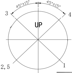
- Position of the piston ring notch.
Oil ring lower retainer 1 Oil ring elastic ring 2 Oil ring upper retainer 3 Second ring 4 Top ring 5
Install Piston
Install the piston using the piston slide rail,
Ensure that the "UP" sign on the top of the piston faces the flywheel.
Note:
When installing, apply oil to the sides of the piston and piston ring.
Install Crankshaft
- 1.Install the bearing bush to the body.
Note:
Before installation, inject oil into the oil channel.
- Install the exhaust cover, thermostat and thermostat cover.
Tighten them at the specified torque twice in the order indicated on the exhaust cover plate.
Locking torque: First time 6 Nm
First time 12 Nm
- Install the locating pin, cylinder gasket and cylinder head assembly.
- Check the keyway position of semicircular key on camshaft
- Tighten the cylinder head bolts to the specified values in 2 steps according to the sequence marked on the cylinder head.
Specified torque:
| 1 st tightening | M9 | 23 Nm |
|---|---|---|
| 2 nd tightening | M9 | 46 Nm |
| 1 st tightening | M6 | 6 Nm |
| 2 nd tightening | M6 | 12 Nm |
Attention:
Do not use old cylinder gaskets.
- Install the timing pulley, driven pulley, timing belt and breather pipe.
Attention:
When installing the timing belt, ensure that the mark on the driven pulley is aligned with the "▼" on the cylinder head; Ensure that the mark on the timing pulley is aligned with the "▼" on the body.
- Adjust valve clearance.
- Install the cylinder head cover and tighten the bolts in the order indicated on the cylinder head cover.
- Install electrical system components in reverse order according to the removal sequence
- Connect the wire of the electrical system.
- Install the fuel system.
Apply oil to the bolts before installation.
- Install oil filter using special tools and tighten it to the specified torque.
- Locking torque: 18 Nm
Upper Casing
Top Cowling
Decomposition Schematic Diagram
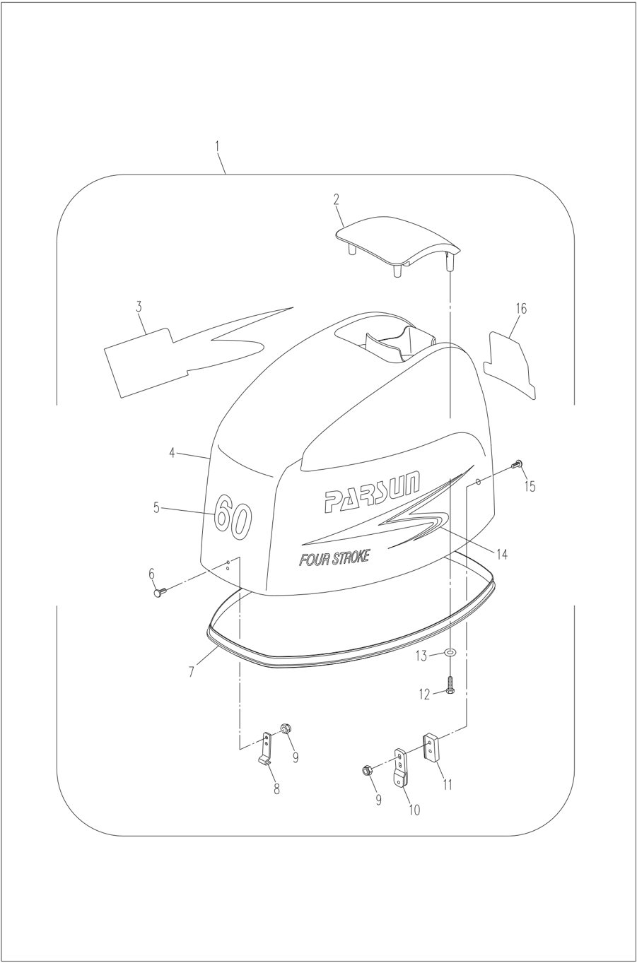
Disassembling and Check
- Remove sealing rubber strip.
- Remove the top cover screws.
- Remove top cover.
- Remove the locking hook and hook.
- Check the top cover for cracks, damage or wear. Replace it if necessary.
- Check the sealing rubber strip for cracks or damage. Replace it if necessary.
- Check the top cover silencer for cracks or damage. Replace it if necessary.
- Check the locking hook and hook for cracks, deformation or damage. Replace it if necessary.
Bottom Cowling
Decomposition Schematic Diagram
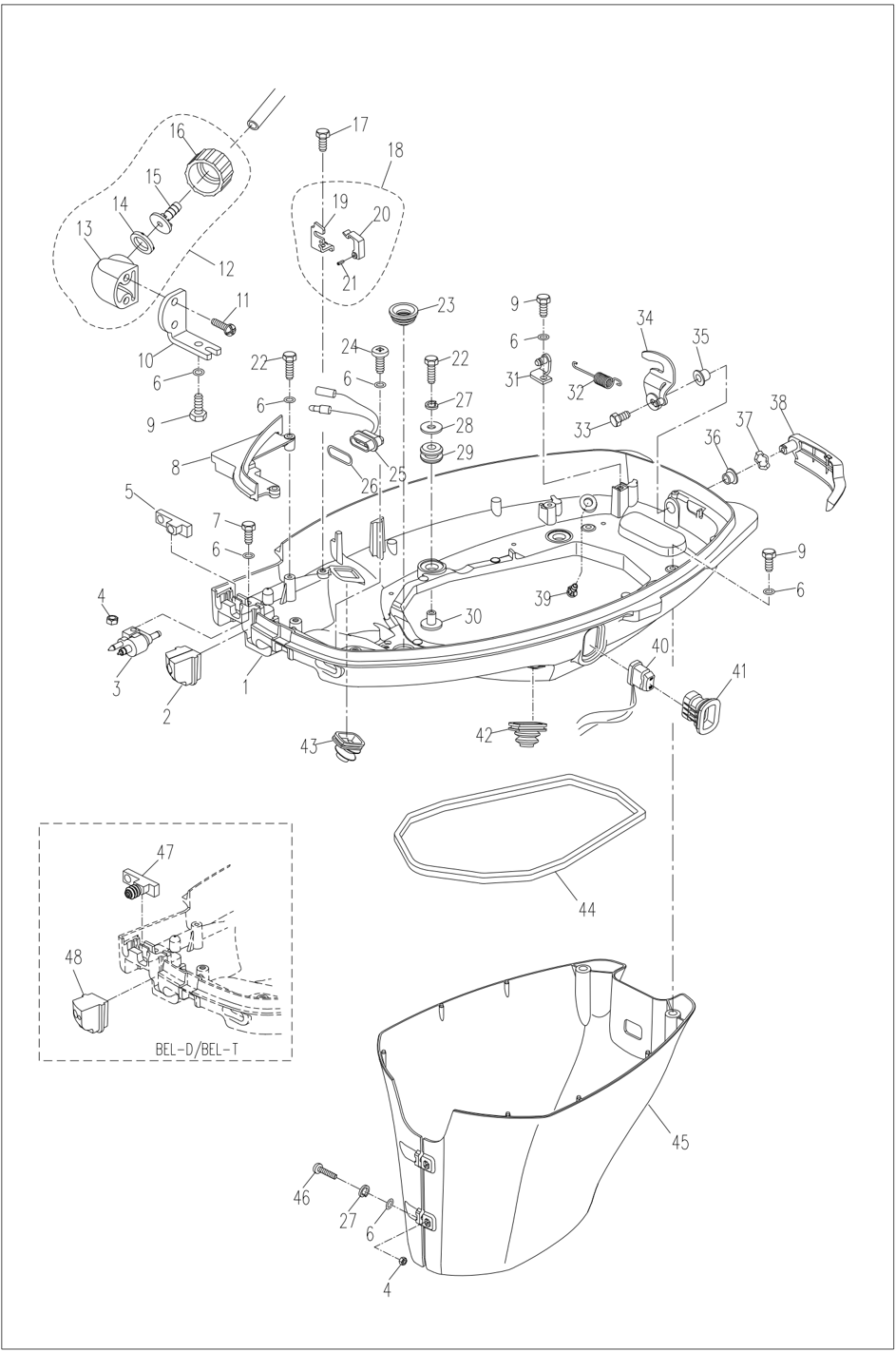
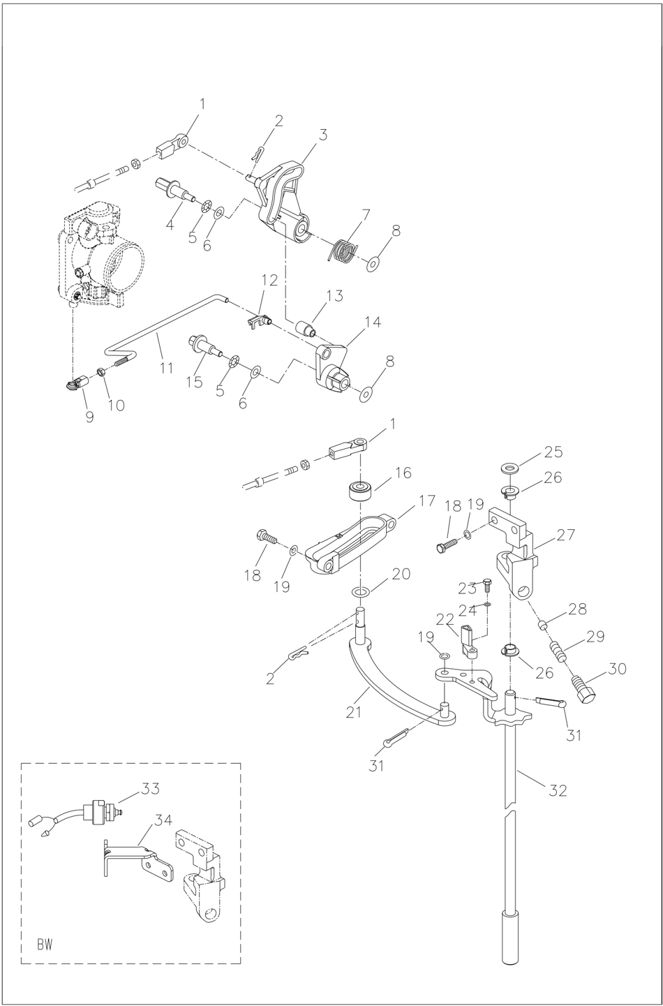
Disassembling and Check
- Remove the rubber plug, corrugated rubber sleeve and throttle cable sheath. Remove the ignition line assembly.
- Remove the bolts securing the small cover plate of the bottom cover, remove the small cover plate of the bottom cover, and remove the square rubber sealing strip. Remove the opening stop plate and the rectangular rubber plug.
- Remove the top cover locking handle screw, remove the top cover locking handle and the top cover locking block.
- Remove the top cover locking handle nylon sleeve A and top cover locking handle nylon sleeve B.
- Remove corrugated washer.
- Remove the control cable connector A and remove the bolts of the throttle swing rod seat.
- Remove the throttle swing rod seat and remove the cotter pin on the throttle swing rod assembly.
- Remove the shift support, remove the shift linkage assembly, and remove the brake rocker.
- Check the top cover for cracks, damage or wear. Replace it if necessary.
- Check the top cover locking handle and the top cover locking block for cracking or damage. Replace it if necessary.
- Check the corrugated washer and lock handle nylon sleeve A for cracks or damage. Replace it if necessary.
- Check the throttle swing rod seat and throttle swing for cracks or damage. Replace it if necessary.
- Check the shift linkage assembly for bending deformation or damage. Replace it if necessary.
- Check whether the shift cam plunger in the shift support slides flexibly. Replace it if necessary.
- For back-operation models, check whether the rocker of the micro switch is worn. Check micro switch conductivity. Replace it if necessary.
Steering Handle
Decomposition Schematic Diagram
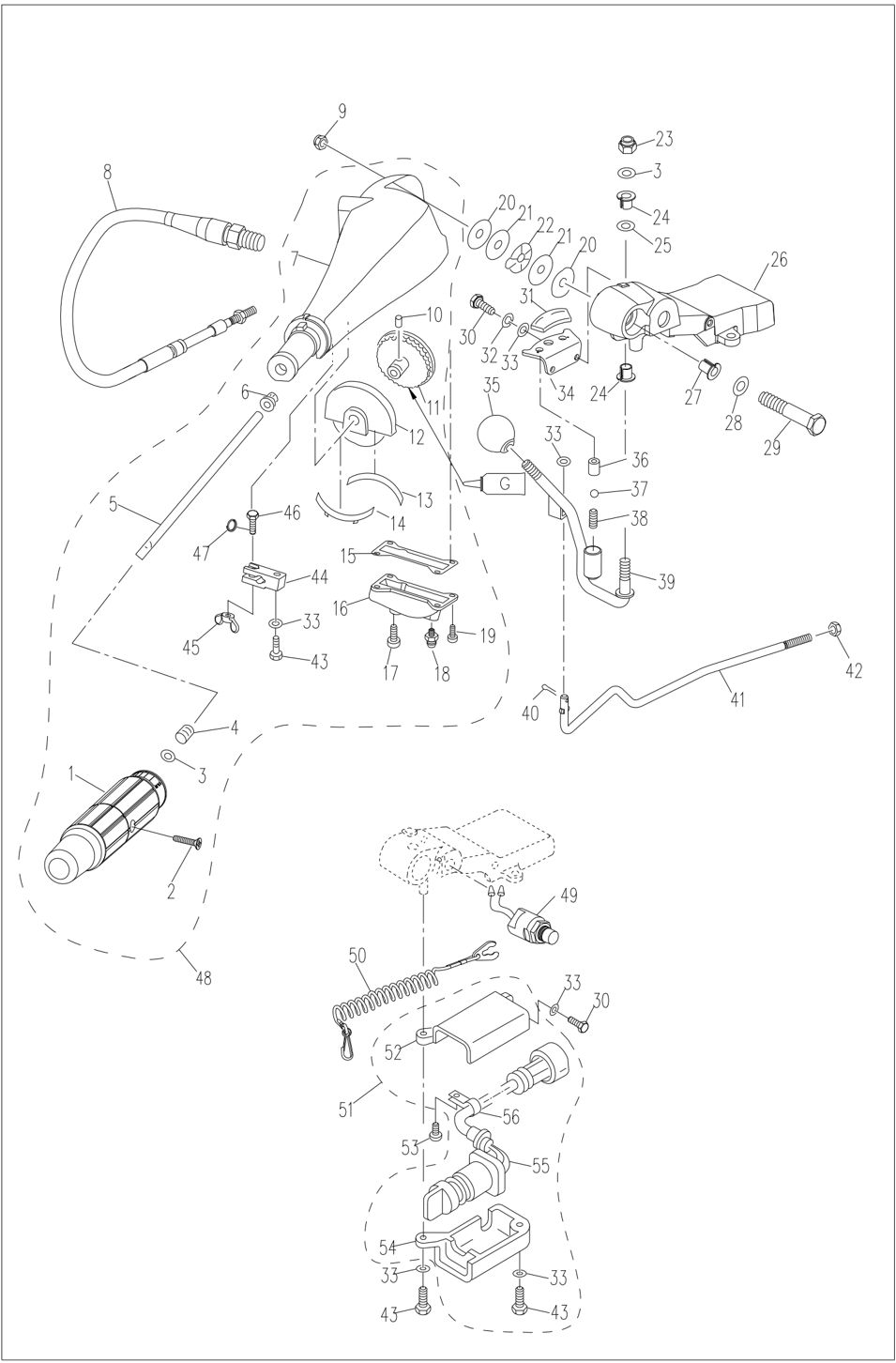
Disassembling and Check
- Remove the handle bracket, remove the shift handle and remove the Steering handle.
- Remove the throttle cable assembly.
- Remove the cotter pin and remove the resistance adjustment knob.
- Remove the throttle grip.
- Remove the throttle cover and throttle lever.
- Remove the engine emergency stop switch.
- Check the steel ball 12 on the shift handle assembly and the shift handle spring for wear, fracture and sticking. Replace it if necessary.
- Check the Steering handle for cracks or damage. Replace it if necessary.
- Check the handle anti-wear ring and waveform washer for cracks or damage. Replace it if necessary.
- Check the cable in the throttle cable assembly for wear or fracture. Replace it if necessary.
- Check the teeth on the throttle lever gear assembly for wear or missing. If yes, replace it.
- Check the conductivity of the engine emergency stop switch; If it does not conform to the regulations, replace it.
Remove locking plate: Conductive
Install locking plate: Not conductive
Press the switch button: Conductive
Upper casing unit and Bracket
Disassembling and Check of Bracket
- Remove the outer cover of the left and right absorbers, remove the left and right absorbers and the retaining nuts of the double-hole absorbers.
- Remove the water unit, oil pan and outlet manifold socket completely from the bracket
- Remove the bracket clamp nut and clamp the bracket double-headed screw tube.
- Disconnect the ground cable A and remove clamping bracket.
- Remove support frame assembly A & B, remove the nylon bushing.
- Remove fixed block limit circlip of the absorber, remove fixed block of the absorber.
Attention:
The absorber fixed block and the steering bracket assembly are splined and tightly connected. Please be careful when disassembling and installing it.
Avoid accidental injuries; Do not disassemble unless necessary.
- Pull out the steering bracket assembly and remove the liner, bushing and O-ring.
- Check the rotary bracket and clamping bracket for cracks or damage. Replace it if necessary.
- Check the bushing and liner; If damaged or cracked, replace it.
- Check the support frame assembly A&B for deformation or damage. Replace it if necessary.
- Check the rubber of the left and right absorbers for aging, cracking or degumming. Replace it if necessary.
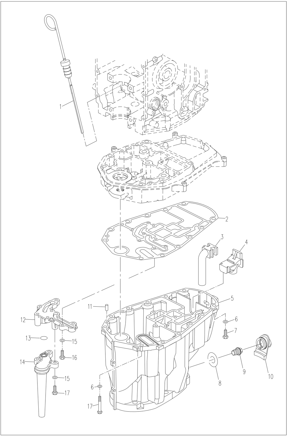
Disassembling and Check of Water Unit
- Drain the oil.
- Remove the mounting bolts on and under the water, and remove the water unit.
- Remove outlet manifold socket, remove the oil pan.
- Remove coarse filter assembly and coarse filter support from the outlet manifold seat.
- Remove the exhaust pipe, oil drain screw, oil drain rubber sleeve and rubber conduit A&B and the outlet manifold from the oil pan
- Remove the exhaust partition and exhaust duct from the oil pan.
- Remove the double-hole absorber, exhaust partition, round rubber ring for water pipe and the water pipe.
- Check the water unit casing and oil pan for cracks or damage. Replace it if necessary.
- Check the exhaust partition for damage or cracks. Replace it if necessary.
- Check the exhaust duct and manifold for cracks or damage. Replace it if necessary.
- Check the exhaust duct sealing ring and the outlet manifold sealing ring for aging or cracking. Replace it if necessary.
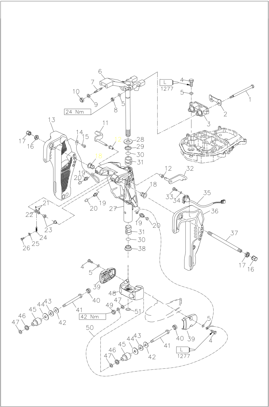
Manual Tilting Device
Disassembly Schematic Diagram
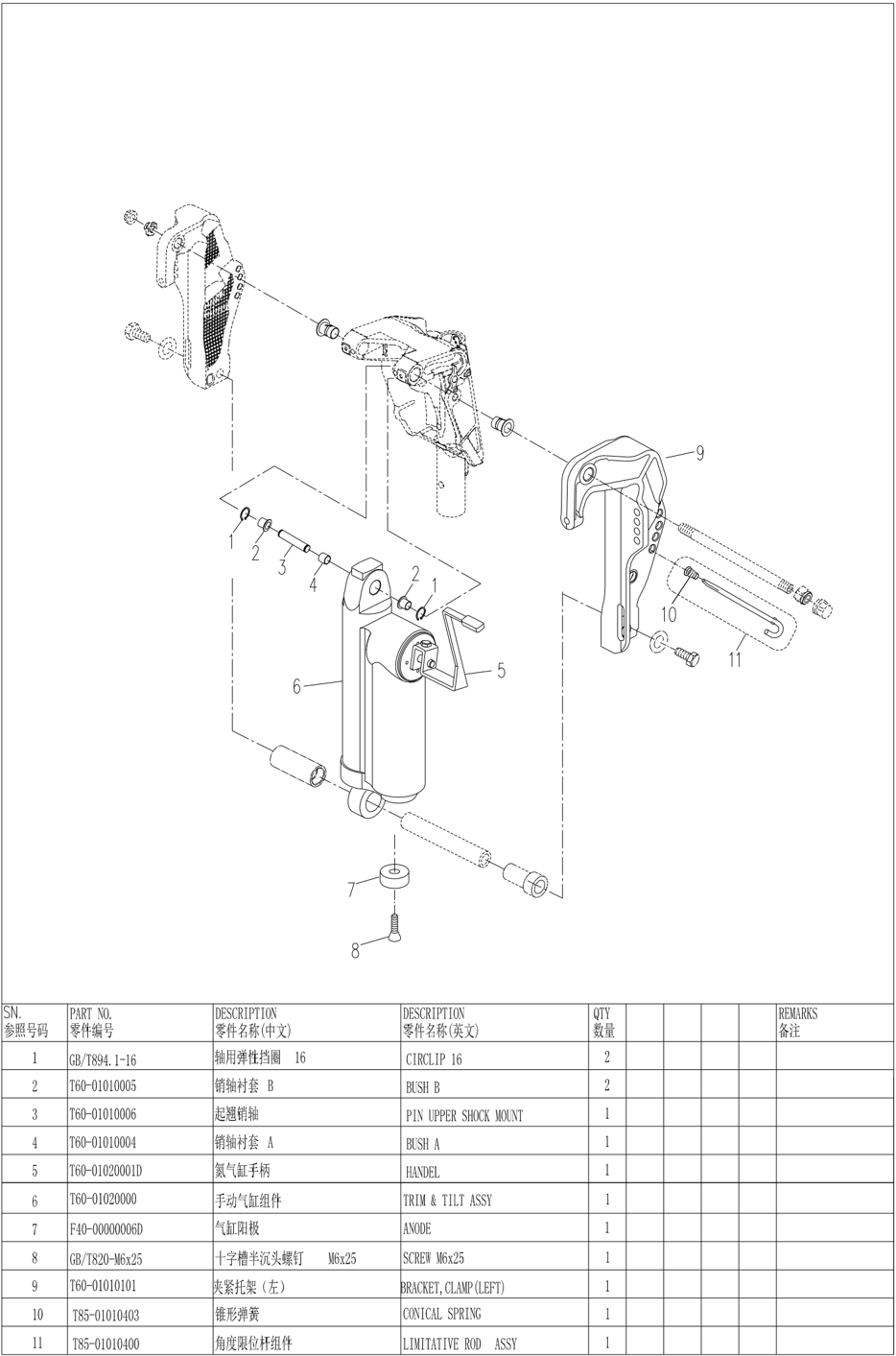
Disassembling Manual Tilting Device
- Fully tilt the outboard motor upwards and lower the support frame to support the outboard motor.
- Remove the steel wire retaining ring for the shaft and remove the tilting pin shaft.
- Remove the bolt and remove the hydraulic tilting positioning shaft.
- Removing the manual cylinder assembly
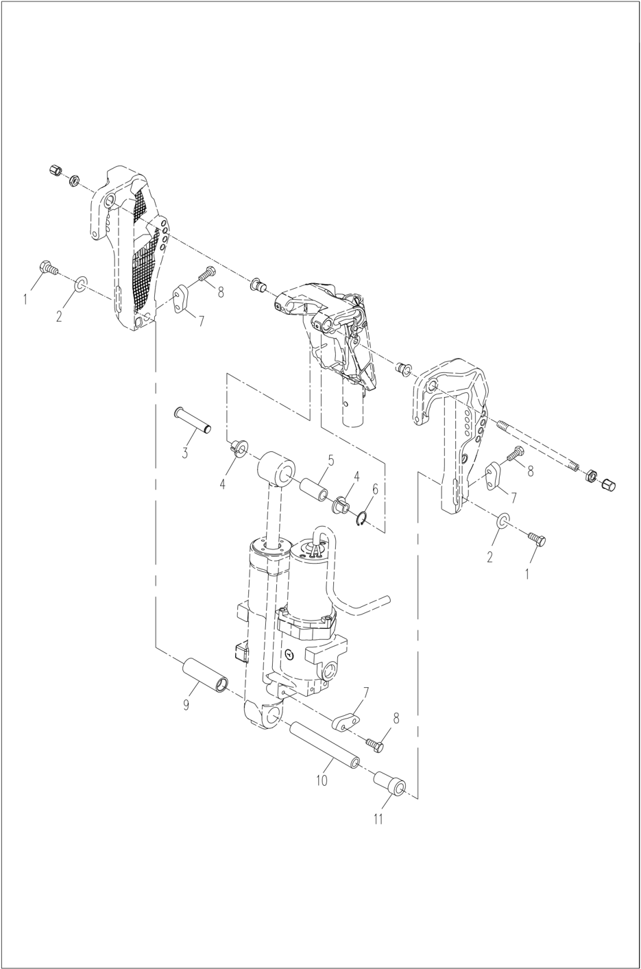
Hydraulic Tilting Device
Disassembling Hydraulic Tilting Device
- Fully tilt the outboard motor upwards and lower the support frame to support the outboard motor.
- Remove the steel wire retaining ring for the shaft and remove the tilting pin shaft.
- Remove the bolt and remove the hydraulic tilting positioning shaft.
- Remove the hydraulic tilting assembly.
Oil Level Check
- Position and secure the hydraulic tilting device vertically.
- Connect the tilting motor wire of the hydraulic tilting device to the battery.
- Extend the push rod completely, remove the oil screw and observe the oil level.
Note:
The liquid level should be at the edge of the oil hole,
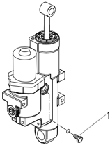
- Oil drain screw
- If necessary, add oil to the edge of the oil hole.
- Install and tighten the oil drain screw.
Specified torque: 6.5 Nm
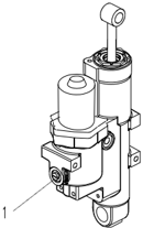
Discharge Air from Oil Circuit of the Hydraulic Tilting Device
After adding oil, discharge the excess air in the oil.
- . Connect the tilting motor wire of the hydraulic tilting device to the battery.
- Extend the push rod completely.
- Change the positive and negative wire connections.
- Compress the push rod completely.
- Repeat steps 1 to 4 to move the push rod up and down for 4 to 5 times.
- Extend the push rod completely, remove the oil screw and observe the oil level.
- If necessary, repeat the above steps until the oil level is correct.
- Install and tighten the oil drain screw.
- Specified torque: 6.5 Nm
If the hydraulic lifting device needs to be vented when installed on the outboard outboard motor, please follow the following steps.
- Turn the hand control valve counterclockwise until it cannot turn.
- Tilt the outboard motor completely upward and then lower it downward by its own gravity. Repeat 4 ~ 5 times.
- Turn the hand control valve clockwise until it cannot turn.
- Wait for 5 minutes to stabilize the oil.
- Press and hold the tilt switch until the outboard motor is fully tilted.
- Wait for 5 minutes to stabilize the oil.
- Remove the oil drain screw and observe the oil level.
- If necessary, repeat the above steps until the oil level is correct.
- Install and tighten the oil drain screw.
- Hand control valve
- Specified torque: 6.5 Nm
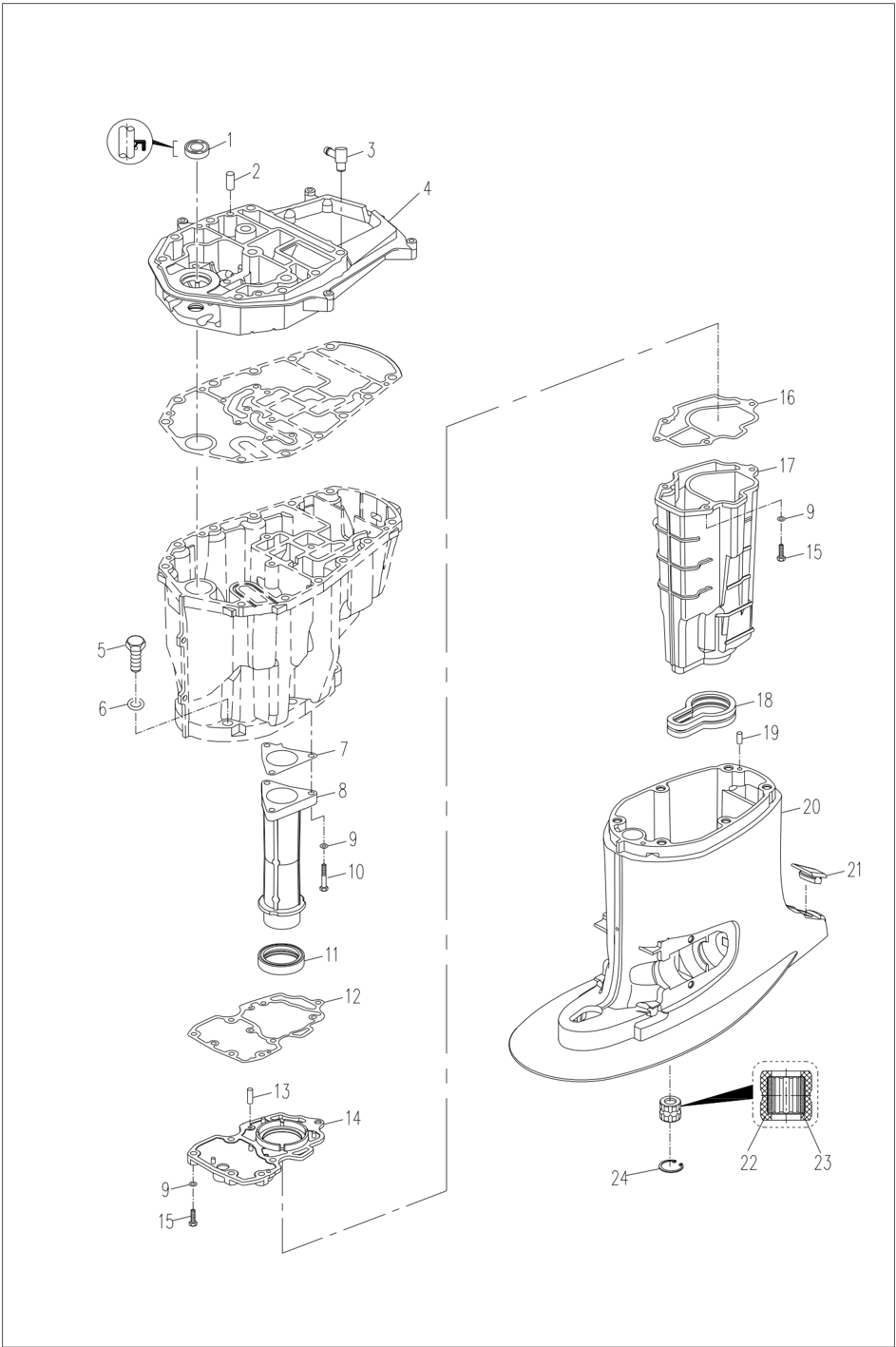
Lower Casing Part
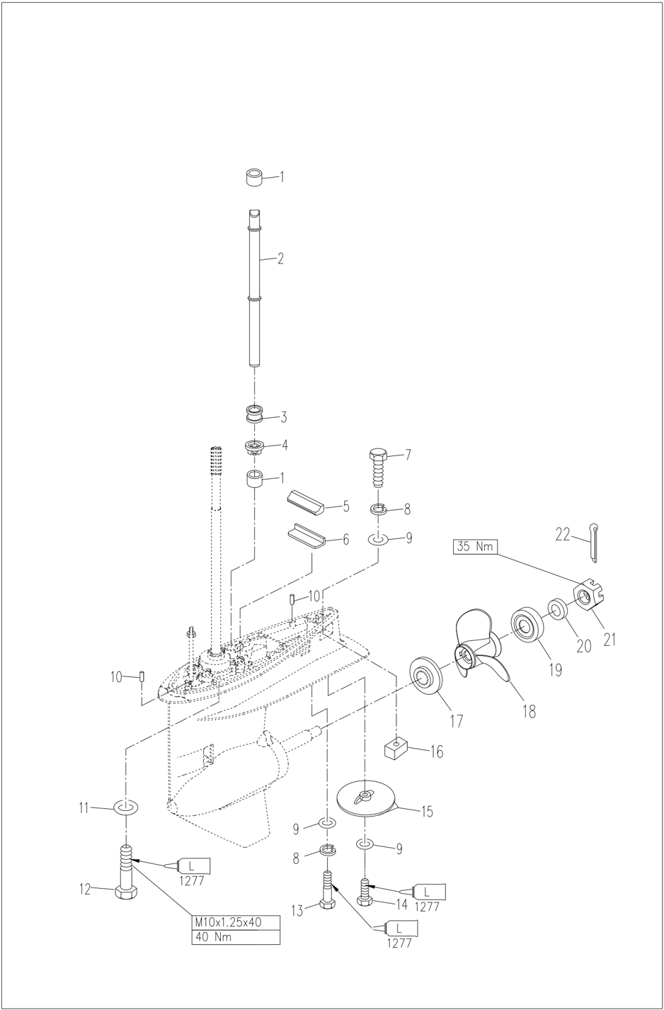
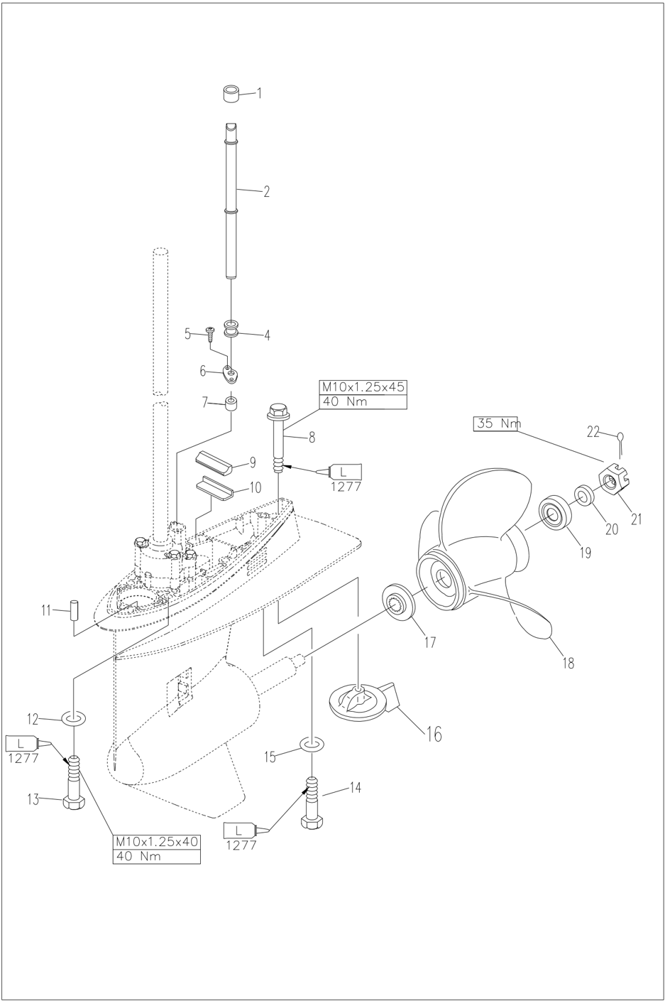
Decomposition Schematic Diagram (D/T model)
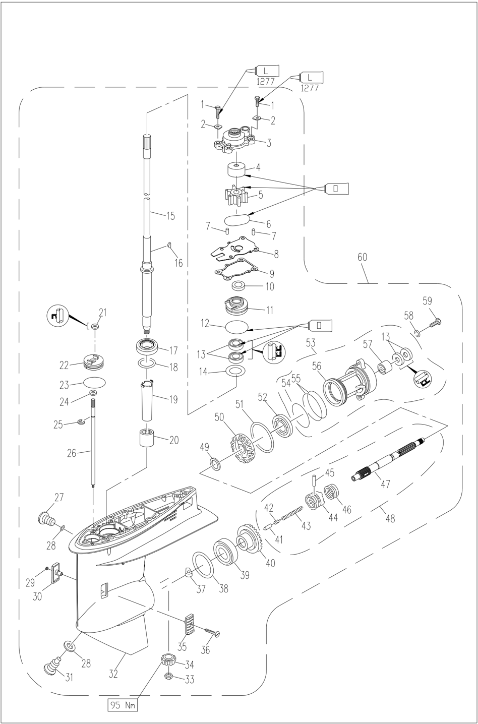
Decomposition Schematic Diagram (CD/CT model)
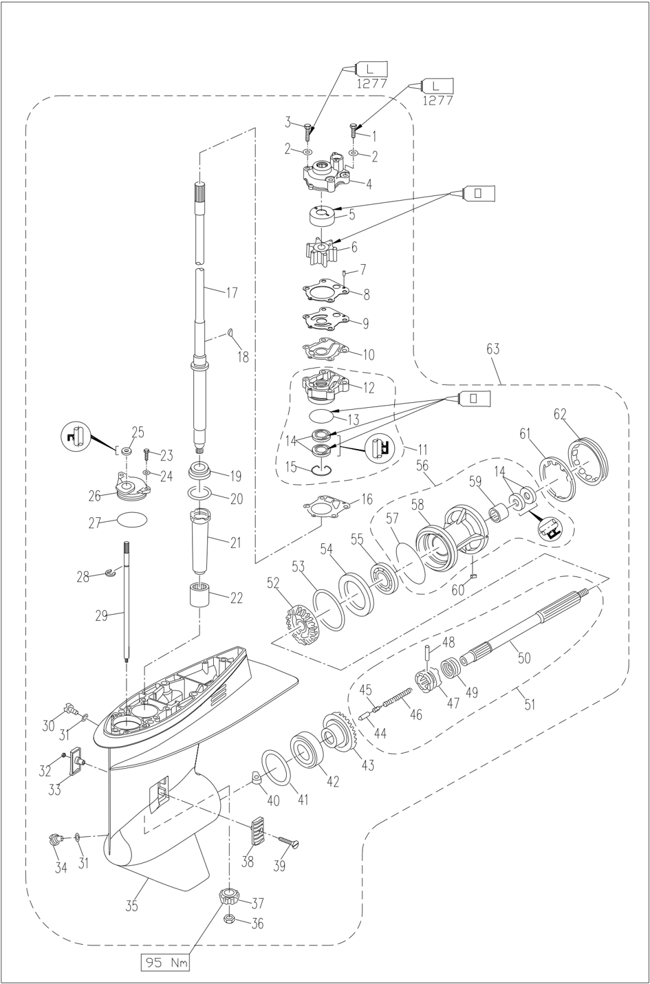
Disassembling and Check
- Remove the water pipe.
- Remove the water pump casing.
- Remove the impeller and pump inner casing.
- Remove the semicircular key and outer baffle.
- Check the water pump casing and outer baffle for cracks, twists or damages. Replace it if necessary.
- Check the water pump inner casing and impeller for cracking, deformation, burning or wear. Replace it if necessary.
- Drain the gear oil.
- Remove the cotter pin; Place the shift lever in neutral position. Place a piece of wood between the swirl plate and the propeller,
to prevent the propeller from rotating freely.
- Remove the slotted hexagon nut, remove the propeller, remove the cushion block.
- Remove the anode and water inlet.
- Remove cover for the Lower casing unit casing. Remove reverse gear and shim and remove oil seal.
- Remove the propeller shaft assembly.
- Remove the shift plunger.
- Remove the clutch ring, clutch pin and claw clutch. Remove the clutch spring.
- Remove the oil seal casing A. Remove water pump seat (CD/CT model)
- Remove the pinion nut with an internal splined wrench and remove the drive shaft.
- Remove shift cam, remove forward gear. Remove shift cam cover plate and remove shift cam. Remove the forward gear (CD/CT)
- Remove the needle roller bearing on the Lower casing unit.
- Remove the oil seal of the oil seal casing A and remove the bearing on the forward gear. Remove the oil seal of the water pump seat and remove the bearing on the forward
gear. (CD/CT)
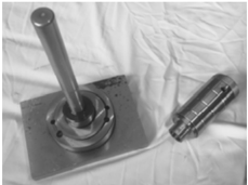
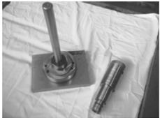
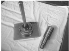
Propeller Shaft and Clutch Block
- Check the claw clutch; If broken or damaged, replace it.
- Check the propeller shaft; If worn or bent, replace it.
Install the Claw Clutch
- Install the clutch spring into the bore at the rear of the propeller shaft.
- Install the claw clutch. Position the "F" or "●" towards the forward gear. Fit the clutch pin.
- Fit the clutch ring and shift plunger.
Note:
When installing the new reverse gear and bearing, adjust the shim as required.
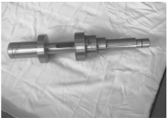
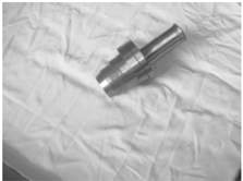
Drive Shaft
Check the drive shaft for bending or wear. Replace it if necessary.
Shift Cam
Check the shift cam for wear or deformation. Replace it if necessary.
Gear
Check the forward gear, reverse gear and pinion for wear or damage. Replace it if necessary.
Lower casing Unit Casing Cover
- Check the bearing for rust and noise when rotating. If yes, replace it.
- Remove the bearing and oil seal with the bearing puller.
Note:
Do not remove the bearing unless it is replaced.
- Remove needle roller bearing with special tools.
Note:
When reinstalling the oil seal and needle roller bearing, use new ones.
- Clean the casing cover with a soft brush and solvent.
- Check the casing cover; If there is cracking or damage, replace it.
Install the Casing Cover Oil Seal and Bearing
- Install the oil seal.
- Fit a new bearing on the reverse gear.
Note:
Install the oil seal and bearing with special tools. Pay attention to the installation direction and depth. Ensure that the manufacturer's mark of the bearing faces the reverse gear. Installation depth:
| Needle roller bearing | Needle roller bearing | 31.0~31.5mm |
|---|---|---|
| Oil seal | Depth 1 | 13.0~13.5mm |
| Oil seal | Depth 2 | 6.0~6.5mm |
Bearing mounting tool Oil seal mounting tool Needle bearing mounting tool
- Install the reverse gear and shim.
Forward Gear Bearing
Check whether the bearing for rust and noise when rotating. Replace it if necessary.
Note:
Do not remove the bearing unless it is replaced.
When installing a new bearing, adjust the shim as required.
Check the Lower casing Unit Casing
Check whether the Lower casing device casing is cracked or damaged, and check whether the cooling water inlet is blocked. Replace it if necessary.
Check the Water Pipe
Check the water pipe for cracks, damage or blockage. Replace it if necessary.
Assemble the Lower casing Device Casing
- Install the needle roller bearing with special tools.
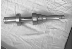
Needle roller bearing mounting tool kit
- Install new forward gear bearing. (If replace it)
Forward gear bearing casing mounting kit
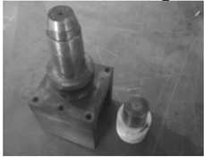
- Install the drive shaft seat oil seal.
- Install the shift cam, gasket and oil pump casing A, and install forward gear, drive shaft, shim and pinion.
Drive shaft seat oil seal installation tool kit

Install the shift cam, gasket and water pump seat, and install forward gear, drive shaft, shim and pinion.
Attention:
When installing a new drive shaft, adjust the shim as required.
- Tighten the pinion nut.
- Install the propeller shaft assembly.
Specified torque: 95 Nm
Note:
If the groove on the nut is not aligned with the cotter pin hole on the propeller shaft, tighten the nut further until it is aligned.
Install the Lower casing Unit
- Install the locating pin.
- Place the shift cam in the forward position. Install the Lower casing unit to the casing of the Lower casing unit and tighten the bolts to the specified value. Specified torque: 37 Nm
- Perform the shift operation and check whether it is operating properly.
- Inject gear oil into the oil drain screw hole with the pressure filling device.
- Install the Lower casing unit casing cover
Lower casing unit casing cover assembly mounting tool
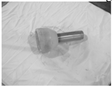
- Check whether the shift gear is working properly.
- Install the water pump assembly.
- Install the anode and water inlet.
- Install the propeller and slotted hexagon nut, and place a piece of wood between the anti-swirl plate and the propeller to prevent the propeller from rotating freely. Tighten the nut to the specified torque, insert the cotter pin and bend the foot of the cotter pin. Specified torque: 35 Nm
Selection of Shims
When replacing the internal parts of the Lower casing unit or assembling a new Lower casing unit, adjust the shims as required.
Deviation Value Mark
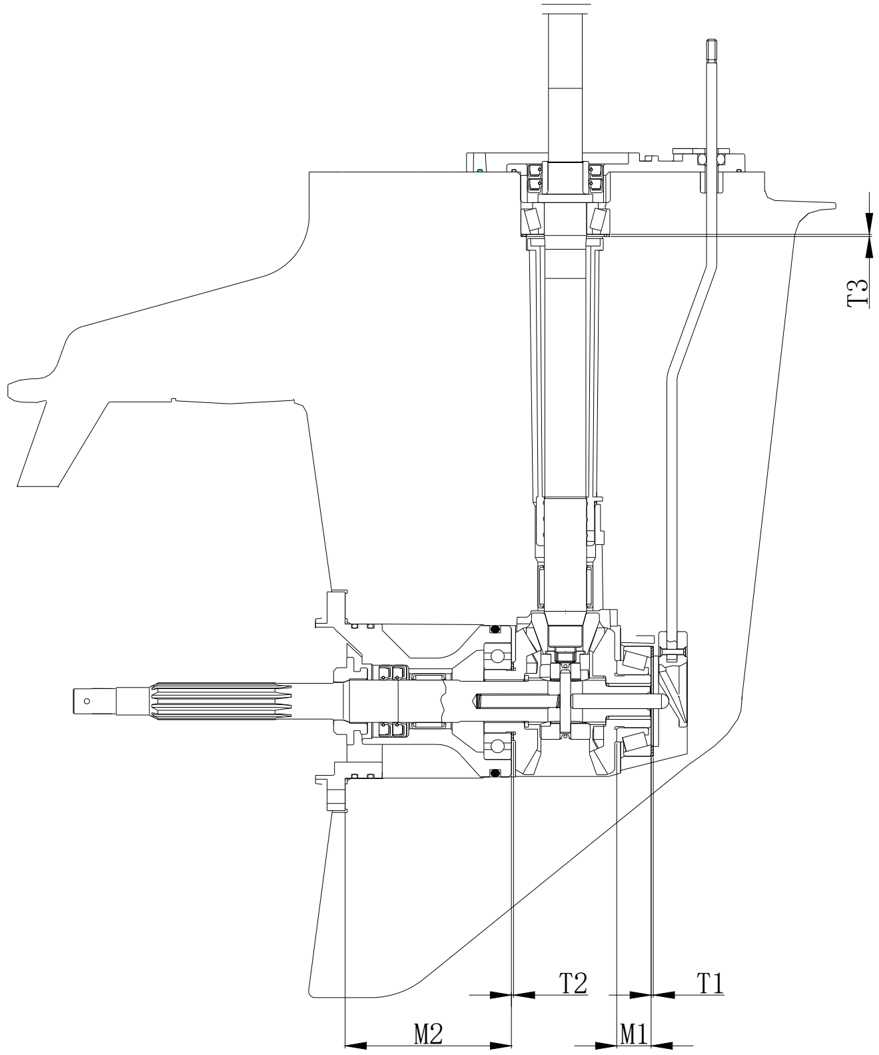
The installation surface of the anode/heading adjusting piece of the Lower casing unit is engraved with deviation value marks, namely F, R and P respectively; Represents the difference between the actual size and the theoretical size on the casing of the Lower casing unit.
For example, the mark P is followed by +3, representing actual size which is 0.03 mmmore than the theoretical If there is no number after that deviation value, the value is considered to be 0.
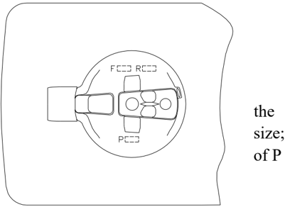
Note:
The thickness of the shim can be 0 ~ 0.05 thinner than T2, and the closest size is selected. For CD/CT, the thickness of the shim can be 0 ~ 0.05 thicker than T2, and the closest size is selected.
Pinion Shim
- Check the P value engraved on the Lower casing unit.
- Attach the drive shaft to the special tool. Fit the pinion and lock the pinion nut according to the specified torque.
Specified torque: 95 Nm
- Measure the clearance between the special tool and the pinion with a gauge,
Formula: T3=M3 - (P/100)
Formula for CD/CT: T3=M3
Calculate the thickness T3 according to the formula.
- (P/100)+0.1
- Shims that can be selected.
Note:
The thickness of the shim can be 0 ~ 0.05 thicker than T3, and the closest size is selected.
Shims for Forward Gear
- Check the F value engraved on the Lower casing unit.
- Turn the outer ring of the forward gear bearing so that the roller falls completely into the bearing casing.
- Measure the bearing height and calculate the thickness T1 according to the formula.
Formula: T1=26.70 + (F/100) - M1
Formula for CD/CT: T1=24.2 + -
(F/100) M1
Note:
When measuring the thickness, it is measured at 3 points. Average the results.
- Shims that can be selected. 0.10, 0.12, 0.15, 0.18, 0.3, 0.4, 0.5 mm
Note:
The thickness of the shim can be 0 ~ 0.05 thinner than T1, and the closest size is selected.
Shims for Reverse Gear
- Check the R value engraved on the Lower casing unit.
- Formula: T2=0.5 + (R/100) Formula for CD/CT: T2=0.5 - (R/100)
- Shims that can be selected. 0.10, 0.12, 0.15, 0.18, 0.3, 0.4, 0.5 mm
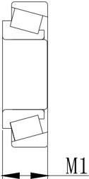
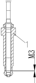
Common Faults and Solutions
| Cause | Solution |
|---|---|
| No fuel in the fuel tank | Fill up the fuel tank with clean fresh fuel |
| Fuel is contaminated or obsolete | Fill up the fuel tank with clean fresh fuel |
| Fuel filter is blocked | Replace the fuel filter |
| Fuel pump failure | Repair or replace the fuel pump |
| Fuel tank cap vent screw not loosened | Loosen the vent screw |
| Spark plug is contaminated or the type is incorrect | Check the spark plug. Clean the spark plug or replace with the correct type of spark plug |
| Incorrect installation of the spark plug cap | Check and reinstall the spark plug cap |
| Ignition wire failure | Check the wiring. Tighten the loose wire and replace aged or broken wire. |
| Ignition parts Failure | Replace |
| The engine stop safety cable is not connected to the emergency stop switch assembly. | Connect the cable to the switch |
| Engine internal parts failure | Repair |
| Spark plug is contaminated or the type is incorrect | Clean the spark plug or replace with the correct type of spark plug |
| Fuel system is clogged | Check the fuel pipe for extrusion, winding or blockage |
| Fuel is contaminated or obsolete | Fill up the fuel tank with clean fresh fuel |
| Fuel filter is blocked | Replace the fuel filter |
| Incorrect spark plug clearance | Adjust the clearance to the specified value |
| Ignition wire failure | Check the wiring. Tighten the loose wire and replace aged or broken wire. |
| Incorrect oil grade | Change to the oil of the specified grade |
| Thermostat failure | Replace |
| Fuel pump failure | Replace |
| The vent screw for the fuel tank cap is not loosened | Loosen the vent screw |
| Fuel joint is not connected correctly | Connect it correctly |
| Chock valve handle is pulled out | Return it to its original position |
| Outboard angle too high | Return it to its normal operating position |
| Propeller is broken | Repair or replace the propeller |
| Incorrect trim angle | Adjust the trim angle to an appropriate angle |
| Incorrect installation height of outboard motor | Adjust it to the correct height |
| The bottom of the ship is polluted by Lower casing organisms. | Clean the bottom of the ship |
| The gearbox is twined by aquatic plants or foreign matters | Remove foreign matter and clean it |
| Engine weakness | Spark plug is contaminated or the type is incorrect |
| Engine weakness | Fuel system is clogged |
| Engine weakness | Fuel filter is blocked |
| Engine weakness | Fuel is contaminated or obsolete |
| Engine weakness | Incorrect spark plug clearance |
| Engine weakness | Ignition wire failure |
| Engine weakness | Ignition parts failure |
| Engine weakness | The engine oil grade is incorrect or too much oil is added. |
| Engine weakness | Thermostat failure |
| Engine weakness | Fuel pump failure |
| Engine weakness | Fuel joint is not connected correctly |
| Engine weakness | Incorrect spark plug specification |
| Excessive vibration of outboard motor | Propeller is broken |
| Excessive vibration of outboard motor | Propeller shaft is broken |
| Excessive vibration of outboard motor | The propeller is twined by aquatic plants or foreign matters |
| Excessive vibration of outboard motor | Mounting bolt of outboard motor is loose |
| Excessive vibration of outboard motor | Steering shaft is loose |
| Excessive vibration of outboard motor | Steering shaft is broken |