
Parsun F2.6 påhængsmotor servicemanual
Indholdsfortegnelse
ADVARSEL:
Generelle oplysninger
Identifikation
Påhængsmotorens serienummer er angivet på mærkaten. Mærkaten findes på venstre ophængsbeslag eller øverst på drejebeslaget. Notér påhængsmotorens serienummer i de dertil beregnede felter, så du lettere kan bestille reservedele hos din Parsun-forhandler. For at modvirke tyveri ødelægges serienummermærkaten, hvis den fjernes fra påhængsmotoren.

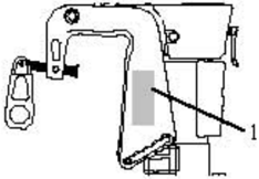
- 1.Placering af påhængsmotorens serienummer. Serienummeret er som følger:
PRODUKTIONSKODE

Valg af propel
Påhængsmotorens ydelse påvirkes i høj grad af dit valg af propel, da et forkert valg kan forringe ydelsen.
Ved større bådbelastning og lavt motoromdrejningstal er en propel med mindre stigning mere egnet. Det korrekte motoromdrejningstal skal opretholdes.
Når motoren kører med fuld gas, skal der anvendes en egnet propel, som vælges ud fra ydelsen.
| Propelstørrelser | Materiale |
|---|---|
| 71/4×6 | Aluminiumlegering |
| 71/4×51/2 | Aluminiumlegering |
| 71/4×71/4 | Aluminiumlegering |
| 71/4×81/4 | Aluminiumlegering |
| 71/2×51/2 | Aluminiumlegering |
Nødstart
Hvis startanordningen ikke fungerer, kan motoren startes med en nødstartsnor.
- Når motoren startes med nødstartsnoren, skal gearstangen være i positionen NEUTRAL.
- Hold genstande på afstand. Rør ikke ved svinghjulet eller andre bevægelige dele.
- Rør ikke ved tændspolen, tændrørshætten eller andre elektriske dele under start og drift.
Proceduren er som følger:
- 1.Fjern den øvre motorkappe.
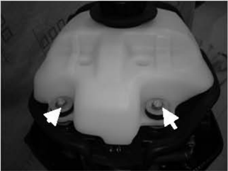
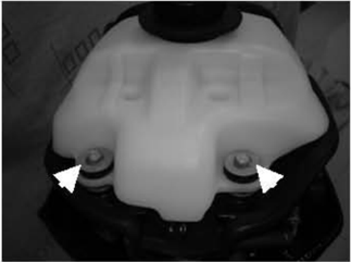
- Fjern boltene, som fastgør brændstoftanken.
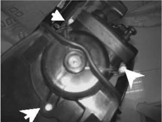
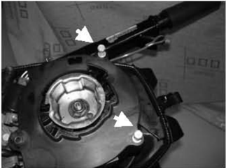
- 3.Løft brændstoftanken, og fjern tre bolte.
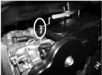
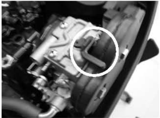
- 4.Løft starteren, og fjern chokerkablet fra karburatoren.
- 5.Fjern starteren.
- Monter boltene, som fastgør svinghjulsdækslet.
- 7.Monter boltene, som fastgør brændstoftanken.
- 8.Når motoren er kold, skal karburatorens arm drejes for at betjene chokersystemet. Før armen tilbage til udgangspositionen, når motoren er startet.
- 9.Sæt snorens knude i hakket på svinghjulsrotoren, og vikl snoren flere omgange med uret rundt om svinghjulet.
- Træk langsomt i det manuelle starthåndtag, indtil du mærker modstand.
- Træk kraftigt for at starte motoren. Gentag efter behov.
Sikkerhed under arbejdet
For at forebygge farer eller ulykker under vedligeholdelse og reparation og samtidig forbedre arbejdseffektiviteten skal følgende sikkerhedsprocedurer følges.
1. Brandforebyggelse
Benzin, smøreolie og fedt er meget brandfarlige. Hold afstand til varme, gnister og åben ild under arbejdet.
2. Ventilation
og dødelig ved indånding i store mængder. Sørg for god ventilation, når en motor prøvekøres indendørs.
3. Personlig beskyttelse
Beskyt øjnene med egnede sikkerhedsbriller eller beskyttelsesbriller ved boring, slibning eller brug af en luftkompressor. Beskyt hænder og fødder med beskyttende arbejdstøj, sikkerhedshandsker og sikkerhedssko efter behov.
4. Smøremidler og tætningsvæsker
Ved vedligeholdelse og reparation af Parsun-påhængsmotorer må der kun anvendes produkter, som leveres eller anbefales af vores virksomhed.
Under normale anvendelsesforhold bør brugen af de smøremidler, der er nævnt i denne manual, ikke medføre nogen risiko. Sikkerhed er dog af største betydning, og ved at følge god sikkerhedspraksis minimeres alle risici.
De vigtigste forholdsregler er sammenfattet nedenfor:
- ① For at beskytte huden anbefales det at påføre en egnet beskyttelsescreme på hænderne før arbejdet.
- ? Tøj, der er blevet tilsmudset med smøremidler, skal skiftes så hurtigt som muligt og vaskes, før det bruges igen.
- ③Undgå hudkontakt med smøremidler.
- @ Hænder og andre kropsdele, der har været i kontakt med smøremidler eller tøj tilsmudset med smøremidler, skal vaskes grundigt med varmt vand og sæbe så hurtigt som muligt.
- Hav rene, fnugfri klude klar til at tørre overskydende smøremidler eller fedt af.
5. God arbejdspraksis
- ① Følg anvisningerne om tilspændingsmoment. Ved tilspænding af bolte, møtrikker og skruer skal de største størrelser spændes først, og de indvendige fastgørelser skal spændes før de udvendige.
- Q Brug det anbefalede specialværktøj for at beskytte delene mod skader. Brug det rigtige værktøj på den rigtige måde.
Afmontering og montering
Følg disse principper ved afmontering og montering:
- Brug specialværktøj ved afmontering og montering.
- 2.Fjern snavs, før delene afmonteres.
- 3.Smør bevægelige deles kontaktflader med olie før montering.
- 4.Monter lejet med producentens mærkning på den synlige side, og smør lejet rigeligt med olie.
- Ved montering af olietætninger påføres et tyndt lag vandfast fedt på læben og den udvendige diameter.
- 6.Kontrollér efter montering, at de bevægelige dele fungerer normalt.
Engangsdele
Engangsdele omfatter pakninger, olietætninger, O-ringe, splitter, fjedre, ringe osv. Ved genmontering af påhængsmotoren skal engangsdelene udskiftes.
Kontrol før levering
For at sikre korrekt funktion skal følgende kontrolleres før levering.
1. Kontrol af brændstofsystem
Kontrollér, at brændstofslangen er forsvarligt tilsluttet, og at brændstoftanken er fyldt med brændstof.
FORSIGTIG:
Brug ikke færdigblandet brændstof til denne 4-takts påhængsmotor.
2. Kontrol af oliestand
Kontrollér motoroliestanden
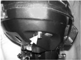
Kontrollér motoroliestanden gennem kontrolhullet til olieniveauet.
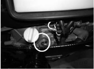
- Øvre niveaumærke 2. Nedre niveaumærke
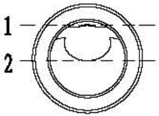
Sørg for, at oliestanden ligger mellem det øvre og det nedre mærke. Hvis den ligger over det øvre mærke, skal motorolie aftappes; hvis den ligger under det nedre mærke, skal der påfyldes motorolie op til det øvre mærke.
Kontrollér gearhusoliestanden
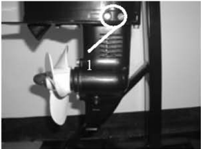
Fjern olieniveauproppen. Kontrollér, om gearhusolien løber ud af kontrolhullet til olieniveauet. Hvis den gør, monteres olieniveauproppen og spændes med det angivne moment.
Ellers skal der påfyldes gearhusolie.
- Olieniveauprop
3. Kontrollér styresystemet
Kontrollér, at styringen er stabil.
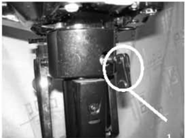
Kontrollér, at styrefriktionen er korrekt justeret. Drej klemmehåndtagets skrue med uret for at øge modstanden.
Drej klemmehåndtagets skrue mod uret for at reducere modstanden.
4. Kontrollér gearstangen og gashåndtaget
Kontrollér, at gearstangen kan betjenes jævnt.
Kontrollér, at gashåndtaget kan drejes jævnt fra helt lukket til helt åben position.
5. Kontrollér nødstopkontakten
Kontrollér, at motoren stopper, når nødstopknappen trykkes ind, eller når nødstopslinen trækkes ud.
6. Kontrollér kontrolhullet til kølevand
Når motoren kører, skal det kontrolleres, om
- Klemmehåndtagets skrue
kølevandet løber ud af kontrolhullet til kølevand.
7. Indkøring
- Første 1 time: Kør motoren ved 2000 r/min eller cirka halv gas.
- ② Anden time: Kør motoren ved 3000 r/min eller cirka 3/4 gas.
- ? De følgende 8 timer: Kør motoren kontinuerligt med fuld gas. Hver driftsperiode må ikke overstige 5 minutter.
8. Inspektion efter indkøring
- ① Kontrollér, om gearhusolien indeholder vand.
- ② Kontrollér, om brændstofslangen lækker.
- ? Efter indkøringen skal motoren køre i tomgang. Skyl kølevandskanalen med ferskvand ved hjælp af rengøringsværktøj.
- 9.Kontrollér tomgangsomdrejningstallet efter indkøringen.
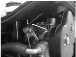
- ② Brug omdrejningstælleren til at måle tomgangsomdrejningstallet i RPM. Justér, hvis det ligger uden for specifikationen. Tomgangsomdrejningstal: 1800~2000 r/min
- ① Varm motoren op i 5 minutter.
- ? Drej gasspjældets stopskrue med eller mod uret, indtil det angivne tomgangsomdrejningstal nås. 1.Gasspjældets stopskrue
- ④ Efter justering af tomgangsomdrejningstallet skal omdrejningstallet øges flere gange for at kontrollere motorens stabilitet.
Specialværktøj og måleudstyr
Ved vedligeholdelse og reparation kræves forskellige specialværktøjer og måleapparater. Korrekt værktøj forbedrer arbejdseffektiviteten og forebygger personskader og skader på påhængsmotoren.
Specialværktøj
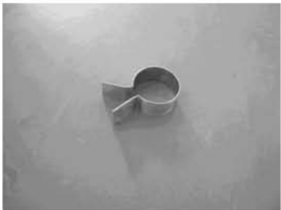
Stempelstyring
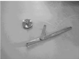
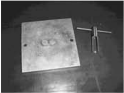
Svinghjulsholder og svinghjulsaftrækker
- Kontrolhul til kølevand
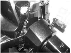
Lejeaftrækker
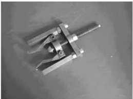
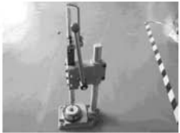
Ventilfjederkompressor
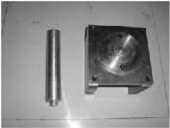
Monteringsværktøj til olietætninger
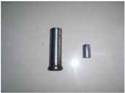
Monteringsværktøj til husets leje
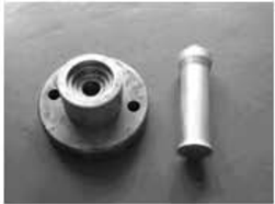
Monteringsværktøj til gearhusdækslets leje
Monteringsværktøj til husets olietætning
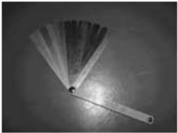
Monteringsværktøj til bøsning med beskyttelsesplade
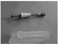
Søgerblad
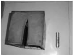
Gearhusstøtte og monteringsværktøj til bøsning uden beskyttelsesplade
Gearhusstøtte og monteringsværktøj til drivakslens olietætning
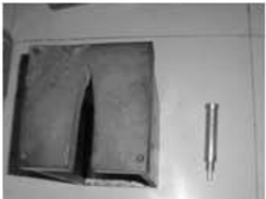
Måleudstyr
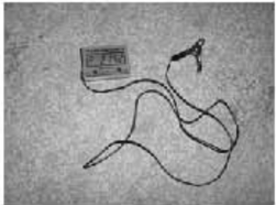
Digital omdrejningstæller
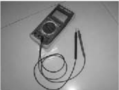
Digitalt multimeter
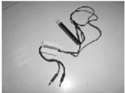
Adapter til spidsspænding
Eksplosionstegning og symboler
Eksplosionstegning
| Nr. | Reservedelsnr. | Beskrivelse | Antal | Bemærkninger |
|---|---|---|---|---|
| 1 | GB/TS743-2000 | Sekskantbolt M6x40 | 4 | |
| 2 | F2.6-03000016 | Vandpumpens fastgørelsesplade | 2 | |
| 3 | F4-03000021 | Vandpumpens gummirør | 1 | |
| 4 | JASO F40419-953 | O-ring til vandpumpens indvendige hus | 1 | |
| 5 | F2.6-03000015 | Vandpumpens indvendige hus | 1 | |
| 6 | F2.6-03000100 | Impellerenhed | 1 | |
| 7 | F2.6-03000010 | Yderplade | 1 | |
| 8 | F2.6-03000009 | O-ring | 1 | |
| 9 | F4-03000013 | Styretap Φ4x18 | 2 | |
| 10 | F2.6-03000007 | Vandpumpens bundpakning | 1 | |
| 11 | F2.6-03000008 | Vandpumpens bund | 1 |
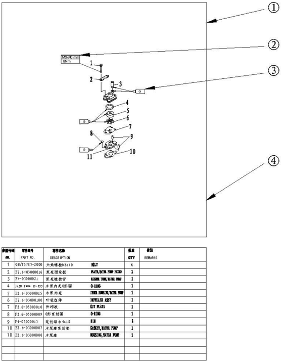
- 1 Eksplosionstegning af delene
- Skruespecifikation og angivet tilspændingsmoment
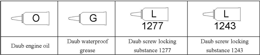
- Påføringssted for olie, flydende tætningsmiddel eller låsemiddel
- Reservedelsoplysninger
Symboler
Specifikationer
Specifikationer for påhængsmotor
| Punkt | Punkt | Beskrivelse | Punkt | Punkt | Beskrivelse |
|---|---|---|---|---|---|
| Dimension | Samlet længde | 645mm | Motorenhed | Tændrør | BPR7HS |
| Dimension | Samlet bredde | 343mm | Motorenhed | Udstødningssystem | Under vand |
| Dimension | Samlet højde | 1013mm | Motorenhed | Smøresystem | Stænksmøring |
| Vægt | Vægt | 18.0kg | Brændstof: | Brændstoftype | Almindelig blyfri benzin |
| Ydelse | Maksimal effekt | 1.9Kw(2.6hp)@5500r/min | Brændstof: | Brændstofstandard | PON86、RON91 |
| Ydelse | Drift med fuld gas | 5250~5750r/min | Brændstof: | Brændstoftankens kapacitet | 1.2L |
| Ydelse | Maksimalt brændstofforbrug | 1.1L/h@5500r/min | Brændstof: | Anbefalet motorolie | APISE、SF、SE-SF、 SG-CD SAE 10W30、10W40 |
| Ydelse | Tomgangsomdrejningstal (neutral) | 1900±100r/min | Brændstof: | Motoroliemængde | 0.35L |
| Motorenhed | Type | 4-takts,OHV | Brændstof: | Anbefalet gearhusolie | Hypoid gearolie SAE #90 |
| Motorenhed | Antal cylindre | 1 | Brændstof: | Gearhusoliemængde | 75mm3 |
| Motorenhed | Slagvolumen | 72cm3 | Beslag | Tiltvinkel | 0°4°,8°,12° |
| Motorenhed | Boring x slaglængde | 54.0mmX31.5mm | Beslag | Optiltningsvinkel | 80° |
| Motorenhed | Kompressionsforhold | 9.0 | Beslag | Styrevinkel | 360° |
| Motorenhed | Antal karburatorer | 1 | Beslag | Gearpositioner | F-N |
| Motorenhed | Styresystem | Rorpindsstyring | Drivenhed | Gearudveksling | 2.08(27/13) |
| Motorenhed | Startsystem | Snorstart | Drivenhed | Geartype | Konisk tandhjul |
| Motorenhed | Tændingsstyringssystem | T.C.I | Drivenhed | Propellens rotationsretning | Med uret |
| Motorenhed | Berigelse ved start | Chokerspjæld | Drivenhed | Propellens drivsystem | Notfortanding |
Vedligeholdelsesoplysninger
Motorenhed
| Punkt | Punkt | Beskrivelse | Punkt | Punkt | Punkt | Beskrivelse |
|---|---|---|---|---|---|---|
| 0.1mm | Ventil | Ventilspillerum (kold motor) | Indsugning | 0.08~0.12mm | ||
| Grænse for skævhed | 0.1mm | Ventil | Ventilspillerum (kold motor) | Udstødning | 0.08~0.12mm | |
| Boring | 54.00~54.015mm | Ventilfladens bredde | Indsugning | 1.84~2.26mm | ||
| Slidgrænse | 54.1mm | Ventilfladens bredde | Udstødning | 1.84~2.26mm | ||
| Grænse for konicitet | 0.08mm | Sædebredde | Indsugning | 0.6~0.8mm | ||
| Grænse for urundhed | 0.05mm | Sædebredde | Udstødning | 0.6~0.8mm | ||
| Stempeldiameter | 58.950~58.965mm | Ventilkantens tykkelse | Indsugning | 0.7mm | ||
| Målepunkthøjde | Omm (fra stemplets bund) | Ventilkantens tykkelse | Udstødning | 1.0mm | ||
| Spillerum mellem stempel og cylinder | 0.035~0.065mm | Ventilhovedets diameter | Indsugning | 23.9~24.1mm | ||
| Stempelboltshullets indvendige diameter | 12.009~12.017mm | Ventilhovedets diameter | Udstødning | 21.9~22.1mm | ||
| Stempelboltens udvendige diameter | Stempelboltens udvendige diameter | 11.995~12.000mm | Stammens udvendige diameter | Indsugning | 5.475~5.490mm | |
| 0.97~0.99mm | Stammens udvendige diameter | Udstødning | 5.460~5.475mm | |||
| Tykkelse Bredde | 1.95~2.15mm | Styrets indvendige diameter, stamme til | Indsugning | 5.500~5.512mm | ||
| Ringgab | 0.15~0.30mm | Styrets indvendige diameter, stamme til | Udstødning | |||
| Slidgrænse | 0.40mm | Spillerum i styret | Indsugning | 0.010~0.037mm | ||
| Sidespillerum | Sidespillerum | Spillerum i styret | Udstødning | 0.025~0.052mm | ||
| 0.04~0.08mm | Grænse for stammens kast | Grænse for stammens kast | 0.03mm | |||
| Tykkelse | 1.17~1.19mm | Grænse for stødstangens kast | Grænse for stødstangens kast | Grænse for stødstangens kast | 0.5mm | |
| Bredde | 2.30~2.50mm | Ventilfjeder | Fri længde | Fri længde | 35.0mm | |
| Ringgab | 0.30~0.45mm | Ventilfjeder | Grænse for fri længde | Grænse for fri længde | 34.0mm | |
| Slidgrænse | 0.60mm | Ventilfjeder | Hældningsgrænse | Hældningsgrænse | 1.2mm | |
| Sidespillerum | 0.02~0.06mm | Plejlstang | Det lille øjes indvendige diameter. | Det lille øjes indvendige diameter. | 12.006~12.02mm | |
| Tykkelse | 1.87~1.95mm | Krumtapaksel | Oliespillerum i plejlstangens store øje | Oliespillerum i plejlstangens store øje | 0.016~0.046mm | |
| Bredde | 2.10~2.40mm | Plejlstangstappens bredde | Plejlstangstappens bredde | 21.0~21.1mm | ||
| Ringgab | 0.20~0.70mm | Plejlstangstappens diameter | Plejlstangstappens diameter | 23.969~23.984m m | ||
| Slidgrænse | 0.90mm | Krumtapakslens lejetapdiameter | Krumtapakslens lejetapdiameter | 21.980~21.993m m | ||
| Sidespillerum | 0.06~0.16mm | Grænse for urundhed | Grænse for urundhed | 0.01mm | ||
| Knastaksel | Indsugnings-/udstødningshøjde | 26.139~26.239mm | Termostat | Ventilens åbningstemperatur | 58~62℃ | |
| Knastaksel | Indsugnings-/udstødningshøjde | 26.139~26.239mm | Termostat | Temperatur ved fuld åbning | 70℃ | |
| Knastaksel | Grundcirkeldiameter | 21.950~22.050mm | Termostat | Ventilløft | 3mm | |
| Knastaksel | Lejetapdiameter | 14.966~14.984mm | Termostat | Ventilløft | 3mm | |
| Knastaksel | Grænse for knastakslens kast | 0.03mm | Termostat | Ventilløft | 3mm |
Tændingssystem
| Punkt | Beskrivelse | Punkt | Punkt | Beskrivelse |
|---|---|---|---|---|
| Tændingstidspunkt | BTDC30° | Tændrørsgab | Tændrørsgab | 0.6~0.7mm |
| T.C.I-systemets udgangsspænding ved spidsen | 130V | Tændingsenhedens modstand | Primærspole | 1.6~1.9Ω |
| T.C.I luftspalte | 0.4~0.6mm | Tændingsenhedens modstand | Sekundærspole | 5.8~7.0K Ω |
Tilspændingsmoment
| Del, der skal spændes | Del, der skal spændes | Del, der skal spændes | Delnavn | Gevindstørrelse | Antal | Tilspændingsmoment |
|---|---|---|---|---|---|---|
| Olieaftapning | Olieaftapning | Bolt | M8 | 1 | 18Nm | |
| Tændrør | Tændrør | M14 | 1 | 25 Nm | ||
| Snorstart | Snorstart | Bolt | M6 | 3 | 8 Nm | |
| Svinghjulsrotorenhed | Svinghjulsrotorenhed | Møtrik | M10 | 1 | 44 Nm | |
| Karburator | Karburator | Bolt | M6 | 2 | 8Nm | |
| Udstødningstester | Udstødningstester | Bolt | M8 | 1 | 20 Nm | |
| Topstykke | 1. tilspænding | Bolt | M8 | 4 | 14 Nm | |
| 2. tilspænding | Bolt | M8 | 4 | 30 Nm | ||
| Cylinder | 1. tilspænding | Bolt | M6 | 6 | 5 Nm | |
| Topstykkedæksel | 2. tilspænding | Bolt | M6 | 6 | 12 Nm | |
| Vippearmens skruebolt | Vippearmens skruebolt | Bolt | M6 | 2 | 10 Nm | |
| Låsemøtrik (vippearm) | Låsemøtrik (vippearm) | Møtrik | M6x0.75 | 2 | 10 Nm | |
| Olietætningshus | Olietætningshus | Bolt | M8 | 1 | 18Nm | |
| Montering af motorenhed | Montering af motorenhed | Bolt | M6 | 6 | 11Nm | |
| Termostatdæksel | Termostatdæksel | Bolt | M6 | 3 | 8 Nm | |
| Krumtaphus | 1. tilspænding | Bolt | M6 | 8 | 5 Nm | |
| 2. tilspænding | Bolt | M6 | 8 | 11 Nm | ||
| Plejlstang | 1. tilspænding | Bolt | M7 | 2 | 5Nm | |
| 2. tilspænding | Bolt | M7 | 2 | 9 Nm | ||
| Oliesprøjtetandhjulsenhed | Oliesprøjtetandhjulsenhed | Bolt | M6 | 1 | 13 Nm | |
| Underenhed | 1. tilspænding | Bolt | M6 | 3 | 3 Nm | |
| Montering | 2. tilspænding | Bolt | M6 | 3 | 8Nm | |
| Gearhusdæksel | 1. tilspænding | Bolt | M6 | 2 | 6Nm | |
| Gearhusdæksel | 2. tilspænding | Bolt | M6 | 2 | 11 Nm | |
| Anode | 1. tilspænding | Bolt | M6 | 1 | 3Nm | |
| Anode | 2. tilspænding | Bolt | M6 | 1 | 8Nm | |
| Vandpumpehus | 1. tilspænding | Bolt | M6 | 4 | 3Nm | |
| Vandpumpehus | 2. tilspænding | Bolt | M6 | 4 | 8Nm | |
| Vandpumpens bund | 1. tilspænding | Bolt | M6 | 1 | 3 Nm | |
| Vandpumpens bund | 2. tilspænding | Bolt | M6 | 1 | 8Nm | |
| Montering af styrehåndtag | Montering af styrehåndtag | Bolt | M8 | 1 | 26 Nm | |
| Gearstangsbeslag | Gearstangsbeslag | Bolt | M6 | 1 | 5Nm | |
| Drejebeslag | Drejebeslag | Møtrik | M6 | 4 | 12 Nm | |
| Klemmebeslag | Klemmebeslag | Møtrik | M8 | 1 | 16 Nm |
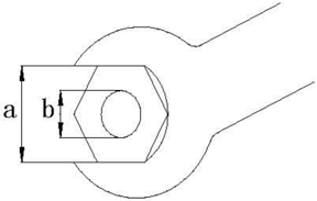
Generelle tilspændingsmomenter
| Møtrik (a) | Bolt (b) | Tilspændingsmoment |
|---|---|---|
| 8mm | M5 | 5Nm |
| 10mm | M6 | 8 Nm |
| 12mm | M8 | 18 Nm |
| 14mm | M10 | 36 Nm |
| 17mm | M12 | 43 Nm |
Periodisk service
Vedligeholdelsesskema
| Punkter | Indhold | Første vedligeholdelse | Første vedligeholdelse | Generelt vedligeholdelsesinterval | Generelt vedligeholdelsesinterval |
|---|---|---|---|---|---|
| Punkter | Indhold | 10 timer (1 måned) | 50 timer (3 måneder) | 100 timer (6 måneder) | 200 timer (1 år) |
| Anode | Inspektion/udskiftning | 0 | |||
| Tændrør | Rengøring/justering/udskiftning | O | |||
| Smørepunkter | Smøring med fedt | O | |||
| Bolte og møtrikker | Inspektion | O | O | ||
| Brændstoftank og brændstofslange | Inspektion | ||||
| Brændstoffilter | Inspektion/udskiftning | O | |||
| Karburator | Inspektion/udskiftning | O | |||
| Påhængsmotorens yderside | Inspektion/udskiftning | O | |||
| Tomgangsomdrejningstal | Inspektion/justering | O | |||
| Motorolie | Udskiftning | O | |||
| Ventilspillerum | Inspektion/justering | O | |||
| Tændingstidspunkt | Inspektion | O | |||
| T.C.I luftspalte | Inspektion/justering | O | |||
| Termostat | Inspektion | O | |||
| Kølevandskanal | Inspektion/rengøring | O | |||
| Gearhusolie | Udskiftning | 0 | |||
| Propel | Inspektion/udskiftning |
FORSIGTIG:
Efter kørsel med påhængsmotoren i saltvand, spildevand eller mudret vand skal motoren straks skylles med ferskvand.
Hvis der ofte bruges blyholdig benzin, skal ventilen og dens komponenter kontrolleres hver 100 timer.
Brændstofsystem
- KONTROLLÉR BRÆNDSTOFTANK, KARBURATOR, BRÆNDSTOFPUMPE OG BRÆNDSTOFSLANGE
Kontrollér brændstoftank, karburator, brændstofpumpe og brændstofslange for skader eller lækager. Udskift efter behov. Kontrollér, om brændstoffilteret på tanken er snavset. Fjern snavs, eller udskift filteret efter behov.
2. Kontrollér brændstofhanen
Kontrollér brændstofhanen for revner, skader eller lækager. Udskift efter behov.
Motorenhed
Motoroliestand
- Kontrollér gennem kontrolhullet til olieniveauet, om motoroliestanden ligger mellem det øvre og det nedre mærke nedenfor.
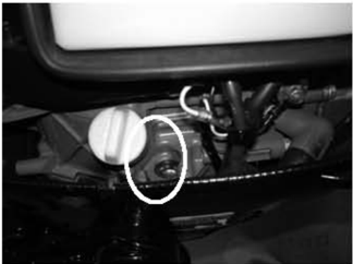
- Olieniveauprop 2.Oliepind
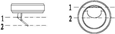
- 3.Øvre niveaumærke 4.Nedre niveaumærke
- Hvis den er over det øverste mærke, skal motorolien tappes af. Hvis den er under det nederste mærke, skal der påfyldes motorolie op til det øverste mærke.
FORSIGTIG:
Lad motoren køre i nogle minutter, og stop den derefter. Vent nogle minutter, og kontrollér motoroliestanden igen gennem kontrolhullet til olieniveauet.
Hvis motorolien stadig ikke har det korrekte niveau, skal der påfyldes eller aftappes olie efter behov.
Udskiftning af motorolie
- Fjern olieniveauproppen og aftapningsproppen med skive og pakning; aftap motorolien.
- Monter en ny pakning og skive; monter aftapningsproppen.
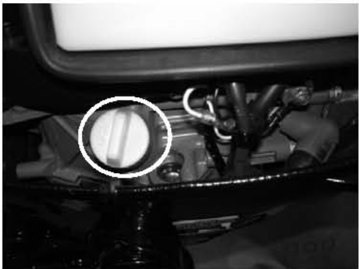
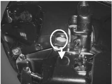
- Fyld motorolie i krumtaphuset gennem oliepåfyldningshullet.
Motoroliemængde: 0.35L
Olietype: API SE, SF, SE-SF, SG-CD SAE 10W30, 10W40
- Monter olieniveauproppen.
- 5.Kontrollér motoroliestanden.
FORSIGTIG:
Drej svinghjulet med uret, så vippearmen er i fri position, før ventilspillerummet justeres (dødpunkt på kompressionsslaget).
- Fjern nødstopssnoren fra nødstopkontakten. Fjern tændrørshætten fra tændrøret.
- 2.Fjern topstykkedækslet.
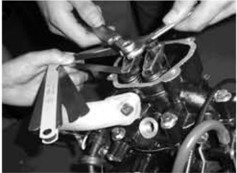
- Brug et søgerblad til at måle spillerummet mellem vippearmen og toppen af ventilstammen: Justér, hvis det ligger uden for specifikationen.
Ventilspillerum (kold motor):0.08~0.12mm
- Fjern tændrørshætten og tændrøret.
Tændrør
- 2.Fjern sodaflejringer fra elektroderne.
- Kontrollér, om elektroderne er korroderede eller har aflejringer, eller om skiven er beskadiget. Udskift tændrøret efter behov.
- Kontrollér, om tændrørsgabet ligger inden for specifikationen. Udskift tændrøret efter behov.
- Monter tændrøret. Brug en tændrørsnøgle til at spænde det med det angivne moment.
Tændrørstype: BPR7HS
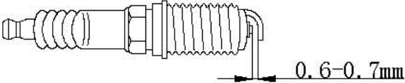
Angivet tilspændingsmoment: 25 Nm
Ventilspillerum
Styresystem
Gashåndtag
- Drej gashåndtaget til helt lukket position.
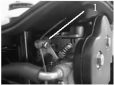
- Kontrollér, om gaskablet er slapt, og om gasspjældsarmen berører gasspjældets stopskrue.
- Løsn gaskablets stopskrue, justér gaskablets position, og spænd gaskablets stopskrue.
1.Gaskablets stopskrue
Tomgangsomdrejningstal
Kontrollér tomgangsomdrejningstallet, og justér efter behov.
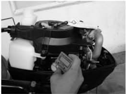
- 1.Varm motoren op i 5 minutter.
- Tilslut omdrejningstælleren til tændrørsledningen for at måle tomgangsomdrejningstallet i RPM. Justér, hvis det ligger uden for specifikationen.
- Drej gasspjældets stopskrue med eller mod uret, indtil det angivne tomgangsomdrejningstal nås.
Tomgangsomdrejningstal: 1800~2000 r/min
BEMÆRK:
Drej med uret for at øge tomgangsomdrejningstallet.
Drej mod uret for at reducere tomgangsomdrejningstallet.
FORSIGTIG:
Gaskablets slæk skal justeres korrekt, før tomgangsomdrejningstallet justeres. Efter justering af tomgangsomdrejningstallet kan gaskablet justeres igen efter behov.
Kontrollér gearhusoliestanden
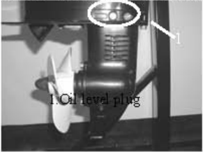
Fjern olieniveauproppen. Hvis gearhusolien løber ud af kontrolhullet til olieniveauet, er den påfyldte oliemængde korrekt; ellers skal der påfyldes gearhusolie.
- Olieniveauprop
Udskiftning af gearhusolie
- 1.Hold påhængsmotoren oprejst.
- 2.Anbring en beholder under aftapningsproppen.
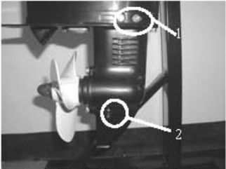
- 3.Fjern aftapningsproppen og olieniveauproppen, og aftap derefter gearhusolien.
- 4.Påfyld gearhusolie gennem aftapningshullet med en trykpåfyldningsanordning.
- Når gearhusolien løber ud af kontrolhullet til olieniveauet, monteres olieniveauproppen 5.
- 6.Monter aftapningsproppen, og tør derefter den overskydende gearhusolie af.
1.Olieniveauprop 2.Aftapningsprop
BEMÆRK:
Kontrollér den aftappede gearhusolie.
Hvis gearhusolien er mælkehvid, skal olietætningen kontrolleres. Udskift olietætningen efter behov.
FORSIGTIG:
Aftapningsproppens skive skal udskiftes hver gang.
Kontrol af underenheden for lækager
Gearhus
Gearhusolie
Tilslut lækagetesteren til kontrolhullet til olieniveauet for at kontrollere underenheden for lækager. Hvis
Generel inspektion
Anode
Kontrollér underenhedens anode og motorens anode (på termostatdækslet). Fjern fedtet snavs og belægninger. Hvis slid eller skader overstiger 1/2, skal anoden udskiftes.
FORSIGTIG:
Anoden må ikke smøres med fedt eller males, da den så ikke fungerer korrekt.
Smørepunkter
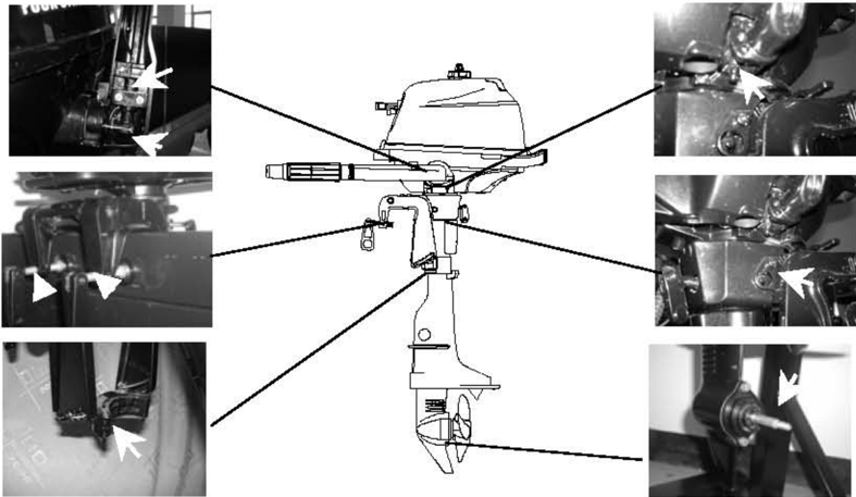
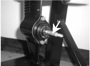
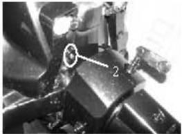
- Se illustrationen med smørepunkter, og påfør vandfast fedt.
- 2.Påfør korrosionsbeskyttende fedt på propelakslen.
Kølevandskanal
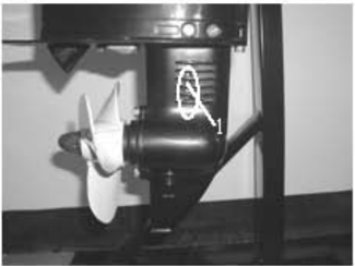
- 1.Kontrollér kølevandskanalen. Rengør den, hvis den er tilstoppet.
Kølevandskanalens indløb
- 2.Anbring påhængsmotoren i vandet, og sørg for, at vandstanden ligger over antivortexpladen. Start derefter motoren.
- 3.Kontrollér, om vand løber ud af kontrolhullet til kølevand. Hvis der ikke er nogen vandstrøm, eller hvis den er uregelmæssig, skal kølevandskanalen kontrolleres.
1.Kølevandsindtag
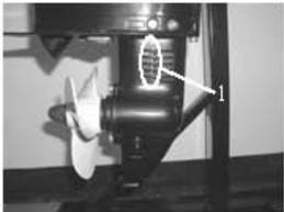
- Kontrolhul til kølevand
Snorstart
MEDDELELSE:
Brug sikkerhedsbriller og handsker under servicearbejdet. Fjern tændrørshætten og nødstopssnoren fra nødstopkontakten for at forhindre utilsigtet start af motoren.
Eksplosionstegning
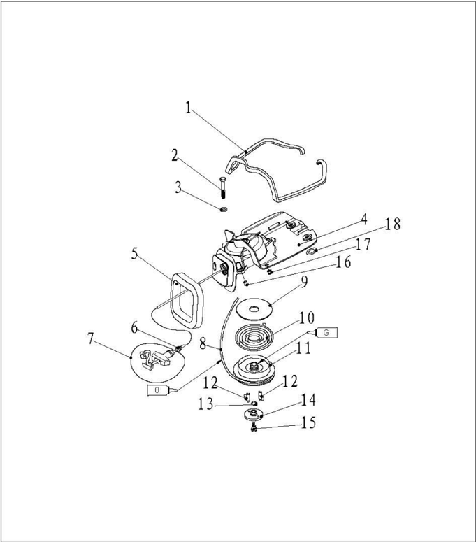
| Nr. | Reservedelsnr. | Beskrivelse | Antal | Bemærkninger |
|---|---|---|---|---|
| 1 | F2.6-04070002 | Skumgummitætning | 1 | |
| 2 | CB/T5782-2000 | BOLT M6x60 | 3 | |
| 3 | CB/T97.1-85 | SKIVE 6 | 3 | |
| 4 | F2.6-04070100 | STARTERHUS | 1 | |
| 5 | F2.6-04070001 | Skumgummitætning | 1 | |
| 6 | F2.6-04070008 | HÅNDTAGSDÆMPER | 1 | |
| 7 | F4-04130100 | STARTHÅNDTAGSENHED | 1 | |
| 8 | F2.6-04070007 | STARTSNOR Φ3 | 1 | |
| 9 | F2.6-04070003 | TRYKSKIVE | 1 | |
| 10 | F4-04130005 | SPIRALFJEDER | 1 |
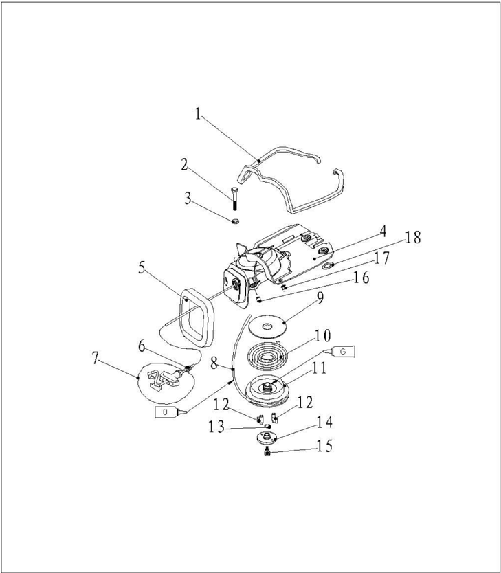
| Nr. | Reservedelsnr. | Beskrivelse | Antal | Bemærkninger |
|---|---|---|---|---|
| 11 | F2.6-04070004 | Snortromle | 1 | |
| 12 | F2.6-04070005 | DRIVPAL | 2 | |
| 13 | F4-04130007 | Starterpladens fjederclips | 1 | |
| 14 | F2.6-04070006 | TRYKPLADE | 1 | |
| 15 | F4-04130008 | STARTERSKRUE | 1 | |
| 16 | F2.6-04000024 | STARTERBØSNING | 3 | |
| 17 | F2.6-04000034 | BRÆNDSTOFTANKDÆMPER B | 2 | |
| 18 | F2.6-04000025 | STARTERBØSNING | 2 |
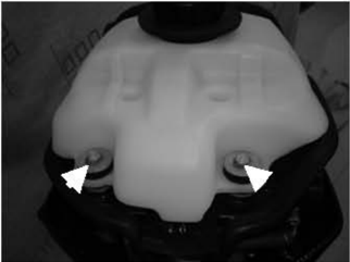
- Åbn den øvre motorkappe.
- 2.Fjern boltene, som fastgør brændstoftanken.
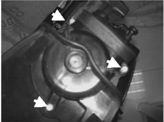
- 3.Fjern brændstoftanken, og fjern tre bolte.
- 4.Løft starteren, og fjern chokerkablet fra karburatoren.
- 5.Fjern starteren.
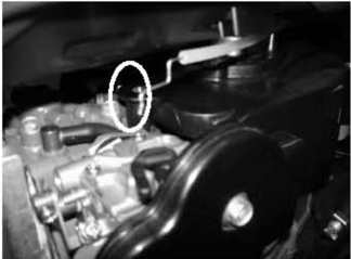
Afmontering
Udskiftning af startsnor
- Træk startsnoren ud, og sæt den i hakket på snortromlen. Drej snortromlen med uret, indtil spiralfjederen er aflastet.
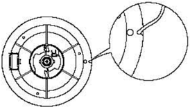
- Træk startsnoren helt ud.
- Fjern starthåndtagets dæksel fra starthåndtaget, og fjern startsnoren. Løsn knuden for enden af startsnoren.
- Træk startsnoren helt ud.
- Før den nye startsnor ind i starterenheden, og fastgør snoren på snortromlen og starthåndtaget. Bind en knude for enden af snoren som vist.
- Sæt startsnoren i hakket på snortromlen, og drej snortromlen flere omgange mod uret.
- Træk i starthåndtaget flere gange for at kontrollere, om snortromlen roterer jævnt. Gentag om nødvendigt trin 6 og trin 7.

Afmontering og inspektion
- Fjern startsnoren.
- Fjern starterbolten, og fjern trykpladen og drivpalen.
- 3.Fjern snortromlen.
- ADVARSEL Afmonter snortromlen forsigtigt, så spiralfjederen ikke springer ud og skader
personer.
- Fjern spiralfjederen.
- Kontrollér drivpalen for revner, slid eller skader. Udskift efter behov.
- Kontrollér drivfjederen for brud, deformation eller skader. Udskift efter behov.
- Kontrollér spiralfjederen for brud, deformation eller skader. Udskift efter behov.
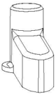

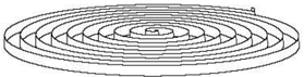
Udfør afmonteringstrinnene i omvendt rækkefølge.
- 1.Anbring starteren på motorenheden.
- 2.Skru sekskantbolten i, og spænd den med det angivne moment. Angivet moment: 8Nm
Tændingssystem
MEDDELELSE:
Hold hænder, tøj, hår og personlige ejendele væk fra det roterende svinghjul under kontrol og reparation af tændingssystemet.
Kontrollér tændspolen på et isoleret arbejdsbord for at forhindre lækstrøm og elektrisk stød.
Rør ikke ved tændspolen eller tændrøret, mens motoren kører, for at undgå elektrisk stød. Hold ledningerne væk fra det roterende svinghjul for at forhindre, at ledningerne skæres over, eller at ledningsisoleringen slides.
Ved udskiftning af fastgørelsesdele som møtrikker og bolte må der kun anvendes dele fra den oprindelige producent eller dele med samme materiale og styrke. Delene skal spændes med de angivne tilspændingsmomenter.
Eksplosionstegning
Montering
Installation
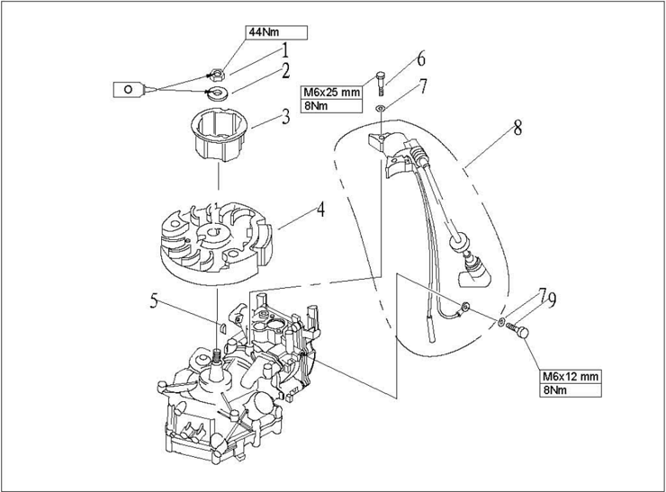
| Nr. | Reservedelsnr. | Beskrivelse | Antal | Bemærkninger |
|---|---|---|---|---|
| 1 | GB/T6171-86 | MØTRIK M10x1.25 | 1 | |
| 2 | F4-04000021 | Svinghjulsskive | 1 | |
| 3 | F2.6-04000016 | Starterbøsning | 1 | |
| 4 | F2.6-04000400 | Svinghjulsenhed | 1 | |
| 5 | F4-04000019 | Svinghjulets halvmånekile | 1 | |
| 6 | GB/T5783-2000 | BOLT M6x25 | 2 | |
| 7 | GB/T97.1-85 | SKIVE 6 | 3 | |
| 8 | F2.6-04000600 | Tændspoleenhed | 1 | |
| 9 | GB/T5783-2000 | BOLT M6x12 | 1 |
Ledningsdiagram
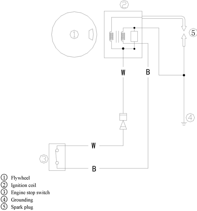
Ledningsnettets farve:W Hvid
B Sort
Tændrørsgnist
- Fjern tændrørshætten fra tændrøret. .
- 2.Tilslut tændingstesteren til tændrørshætten.
- 3.S Start motoren, og iagttag gnisterne gennem testerens gnistvindue.
ADVARSEL:
Rør ikke ved nogen samlinger på testerens ledning.
Hold afstand til brandfarlig gas eller væske for at forhindre ulykker forårsaget af gnisttænding.
- Tændspolens spidsspænding
- Fjern tændrørshætten.
- ② Afbryd tændspolens tilslutning (W).
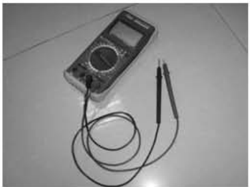
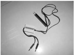
- ③ Mål tændspolens udgangsspænding ved spidsen med et digitalt multimeter og en adapter til spidsspænding. Kontrollér tændspolen, hvis værdien ligger under specifikationen.
Udgangsspænding ved spidsen: 130V (1500 r/min)
Digitalt multimeter
- Tændspolens modstand
- (1 Fjern tændspolen og tændrørshætten.
- Mål tændspolens modstand. Udskift den, hvis værdien ligger uden for specifikationen.
- Modstand: 1.6~1.9 Q(Testerens (+) pol: hvid ledning; testerens (-) pol: sort ledning) 5.8~7.0k Q (Testerens (+) pol: hvid ledning; testerens (-) pol: højspændingsledning)
Adapter til spidsspænding
Tændrørshætte
- 1.Fjern tændrøret. Kontrollér, om tændrørshætten er beskadiget. Udskift efter behov.
- Monter tændrørshætten. Drej den med uret, indtil den sidder fast.
Vedligeholdelse af svinghjul
- 1.Brug en svinghjulsholder til at fjerne møtrikken og starterskiven, og brug en svinghjulsaftrækker til at fjerne svinghjulet.
- 2.Kontrollér, om svinghjulet er beskadiget, og om permanentmagnetdelen sidder fast. Udskift efter behov.
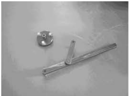
Inspektion af tændspole
Brændstofsystem (detaljeret)
MEDDELELSE:
Benzin er en brandfarlig og meget flygtig væske. Lækager kan medføre brand og eksplosion. Start ikke motoren, før alle brændstofsystemets samlinger er tilsluttet eller monteret. Når alle vedligeholdelsestrin er afsluttet, skal brændstofsystemet kortvarigt tryksættes for at kontrollere for lækager.
Eksplosionstegning
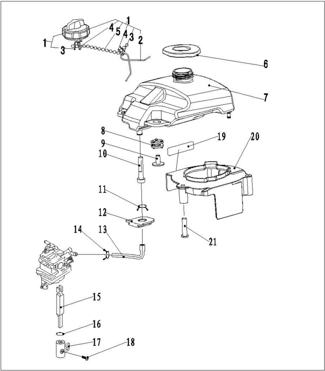
| Nr. | Reservedelsnr. | Beskrivelse | Antal | Bemærkninger |
|---|---|---|---|---|
| 1 | F4-04120100 | TANKDÆKSELENHED | 1 | |
| 2 | F4-04120103 | Torsionsfjeder mod tab | 1 | |
| 3 | F4-04120105 | Fastholdelsesklemme mod tab | 2 | |
| 4 | F4-04120106 | Låsering af ståltråd | 2 | |
| 5 | F4-04120104 | Fastholdelseskæde | 1 | |
| 6 | F2.6-04000033 | Dæmper ved brændstoftankens åbning | 1 | |
| 7 | F2.6-04000026 | Indbygget brændstoftank | 1 | |
| 8 | F2.6-04000027 | Brændstoftankdæmper A | 2 | |
| 9 | F2.6-04000028 | Brændstoftankens dæmperrør | 2 | |
| 10 | F4-04120005 | Brændstoftankfilter | 1 |
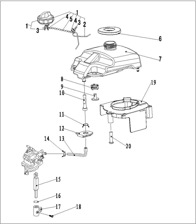
| Nr. | Reservedelsnr. | Beskrivelse | Antal | Bemærkninger |
|---|---|---|---|---|
| 11 | F4-05000010 | OLIESLANGEFJEDER | 1 | |
| 12 | F4-04000032 | OLIESLANGEDÆMPER | 1 | |
| 13 | F2.6-04000029 | Brændstofslange | 1 | |
| 14 | F2.6-04000030 | Brændstofslangefjeder C | 1 | |
| 15 | F2.6-04000017 | Brændstofafspærringsventilens forbindelsesstang | 1 | |
| 16 | JASOF40424-014 | Brændstofafspærringsventilens O-ring Φ13.8x2.4 | 1 | |
| 17 | F2.6-00000004 | OLIEKONTAKTKNAP | 1 | |
| 18 | CB/T823-2000 | Skrue med panhoved M5x8 | 1 | |
| 19 | F2.6-04000022 | Svinghjulets luftføring | 1 | |
| 20 | F2.6-04000023 | Afstandsrør til luftføring | 3 |
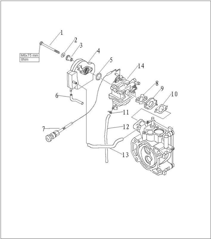
| Nr. | Reservedelsnr. | Beskrivelse | Antal | Bemærkninger |
|---|---|---|---|---|
| 1 | GB/T5782-2000 | BOLT M6x75 | 2 | |
| 2 | GB/T97.1-85 | SKIVE 6 | 2 | |
| 3 | F2.6-04000012 | BØSNING TIL INDSUGNINGSLYDDÆMPER | 2 | |
| 4 | F2.6-04000300 | Indsugningslyddæmperenhed | 1 | |
| 5 | JAS0F40424-021 | Indsugningslyddæmperens O-ring | 1 | |
| 6 | F2.6-04000015 | Udluftningsslange B Φ2.5xΦ7x72 | 1 | |
| 7 | F2.6-04070200 | Chokerhåndtagsenhed | 1 | |
| 8 | F2.6-04000018 | LUFTTÆT KARBURATORPAKNING | 1 | |
| 9 | F2.6-04000011 | KARBURATORISOLATOR | 1 | |
| 10 | F2.6-04000010 | LUFTTÆT KARBURATORPAKNING | 1 | |
| 11 | HT2.5x60 | KLEMME 60x2.5 | 1 | |
| 12 | F2.6-04000013 | Karburatorens aftapningsslange Φ4xΦ7x140 | 1 | |
| 13 | F2.6-04000014 | Udluftningsslange A Φ5xΦ9x130 | 1 | |
| 14 | F2.6-04000200 | Karburatorenhed | 1 |
Afmontering og inspektion af brændstoftank

- Åbn den øvre motorkappe.
- 2.Fjern to bolte, som fastgør brændstoftanken.
- Træk brændstoftanken ud.
- Fjern brændstofslangen fra brændstoftanken.
- Kontrollér brændstoftanken og tankdækslet for revner, lækager eller skader. Udskift efter behov.
- Kontrollér tanksien for snavs eller tilstopning. Rengør eller udskift efter behov.
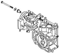
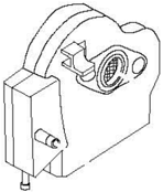
Afmontering og inspektion af indsugningssystem
- 1.Fjern bolten, som fastgør luftfilteret.
- 2.Fjern luftfilteret og karburatoren.
- 3.Kontrollér luftfilteret for revner eller skader. Udskift efter behov.
Motorenhed (detaljeret)
MEDDELELSE:
Træf tilstrækkelige sikkerhedsforanstaltninger for at forhindre utilsigtet start af påhængsmotoren under vedligeholdelse, og fjern tændrørshætten fra tændrøret.
Eksplosionstegning
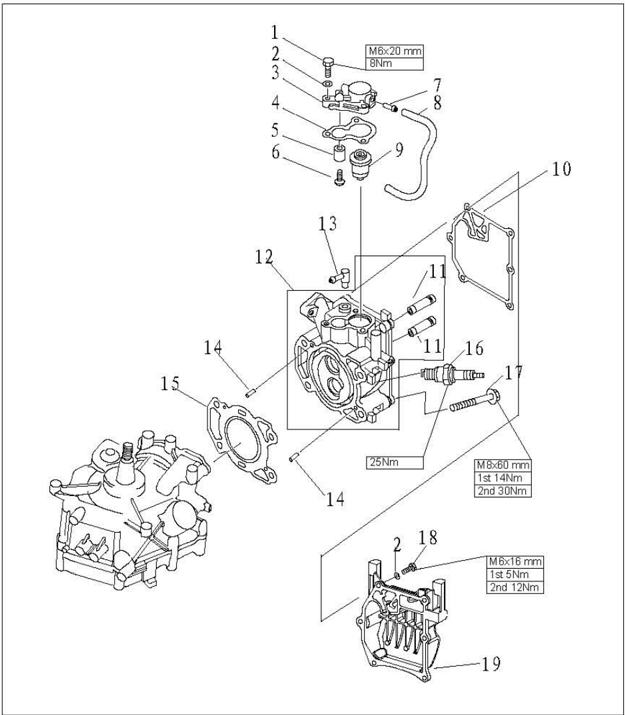
| Nr. | Reservedelsnr. | Beskrivelse | Antal | Bemærkninger |
|---|---|---|---|---|
| 1 | GB/T5783-2000 | BOLT M6X20 | 3 | |
| 2 | GB/T97.1-85 | FLADSKIVE 6 | 9 | |
| 3 | F2.6-04000501 | TERMOSTATDÆKSEL | 1 | |
| 4 | F4-04000011 | TERMOSTATPAKNING | 1 | |
| 5 | P4-04070003 | Termostatdækslets anode | 1 | |
| 6 | GB/T818-85 | Skrue med panhoved M5x25 | 1 | |
| 7 | F4-04010002 | Vandrørssamling | 1 | |
| 8 | F2.6-04000007 | VANDRØR Φ5xΦ9x245 | 1 | |
| 9 | T15-04000010 | TERMOSTAT | 1 | |
| 10 | F2.6-04000005 | CYLINDERDÆKSELPAKNING | 1 | |
| 11 | 166F-010104 | VENTILSTYREBØSNING | 2 | |
| 12 | F2.6-04040100 | TOPSTYKKEENHED | 1 | |
| 13 | F15-04000005 | Vanddyseenhed (7/6) | 1 | |
| 14 | P15-00000013 | TAP 4x12 | 2 |
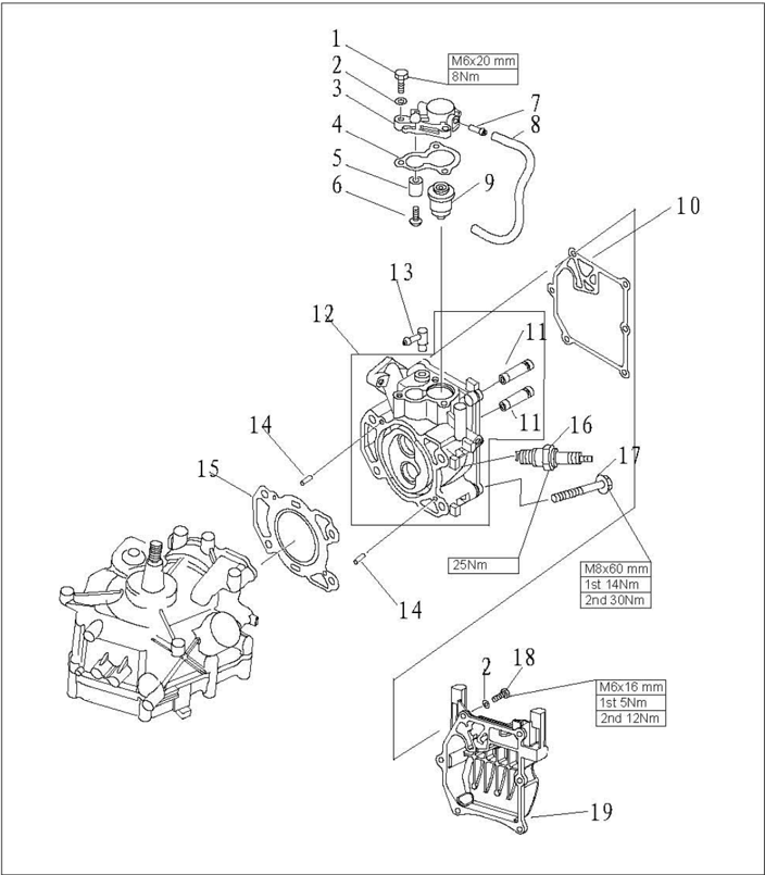
| Nr. | Reservedelsnr. | Beskrivelse | Antal | Bemærkninger |
|---|---|---|---|---|
| 15 | F2.6-04000001 | TOPSTYKKEPAKNING | 1 | |
| 16 | BPR7HS | TÆNDRØR | 1 | |
| 17 | F4-04000034 | BOLT | 4 | |
| 18 | GB/T5783-2000 | BOLT M6x16 | 6 | |
| 19 | F2.6-04000006 | TOPSTYKKEDÆKSEL | 1 |
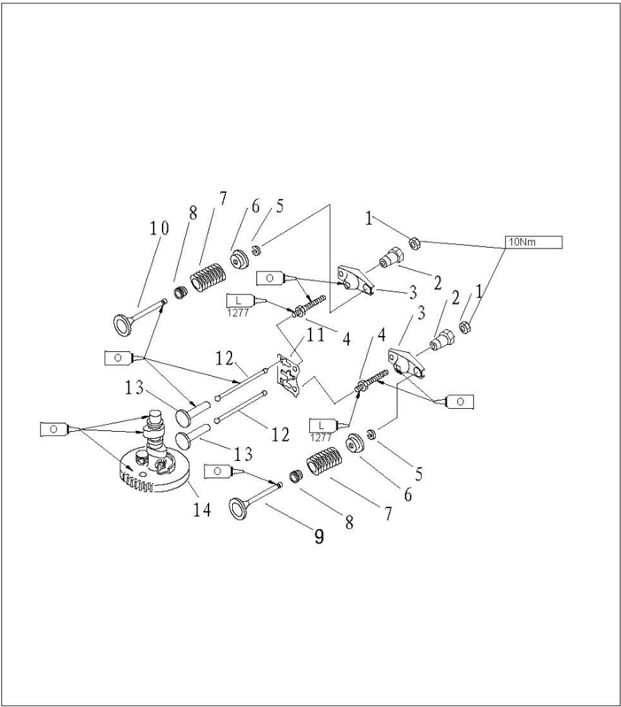
| Nr. | Reservedelsnr. | Beskrivelse | Antal | Bemærkninger |
|---|---|---|---|---|
| 1 | 166F-010011 | LÅSEMØTRIK | 2 | |
| 2 | 166F-010010 | VIPPEARMENS DREJEPUNKT | 2 | |
| 3 | 166F-010009 | VENTILVIPPEARM | 2 | |
| 4 | 116F-010008 | VIPPEARMSBOLT | 2 | |
| 5 | 166F-010006 | VENTILKLEMME | 2 | |
| 6 | F4-04080010 | VENTILFJEDERHOLDER | 2 | |
| 7 | F4-04080008 | VENTILSTAMMEFJEDER | 2 | |
| 8 | 166F-010003 | VENTILSTAMMETÆTNING | 2 | |
| 9 | 166F-010001 | INDSUGNINGSVENTIL | 1 | |
| 10 | 166F-010002 | UDSTØDNINGSVENTIL | 1 | |
| 11 | F2.6-04040001 | STØDSTANGSPLADE | 1 | |
| 12 | F2.6-04000002 | VENTILSTØDSTANG | 2 | |
| 13 | 166F-000001 | VENTILLØFTER | 2 | |
| 14 | F2.6-04000100 | KNASTAKSELENHED | 1 |
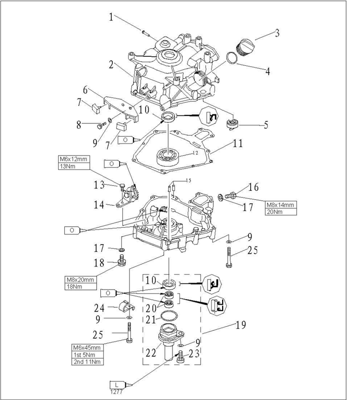
| Nr. | Reservedelsnr. | Beskrivelse | Antal | Bemærkninger |
|---|---|---|---|---|
| 1 | T15-04010202 | VANDRØR | 1 | |
| 2 | F2.6-04010100 | KRUMTAPHUS | 1 | |
| 3 | F15-07050004 | OLIEPROP | 1 | |
| 4 | JAS0F40431-020 | O-RING JAS0F40431-020 | 1 | |
| 5 | F2.6-04010102 | OLIEPIND | 1 | |
| 6 | F2.6-04000008 | DÆMPERBESLAG | 1 | |
| 7 | F2.6-04000009 | GUMMIDÆMPERBLOK | 2 | |
| 8 | GB/T5783-2000 | BOLT M6x20 | 2 | |
| 9 | GB/T97.1-85 | SKIVE 6 | 11 | |
| 10 | F2.6-04010001 | Krumtapakslens olietætning SD20x30x7HS | 2 | |
| 11 | F2.6-04000004 | SAMMENSAT KRUMTAPHUSPAKNING | 1 | |
| 12 | 62/22C3 | KUGLELEJE | 1 | |
| 13 | GB/T5783-2000 | BOLT M6x12 | 1 | |
| 14 | F2.6-04050100 | TANDHJULSENHED | 1 |
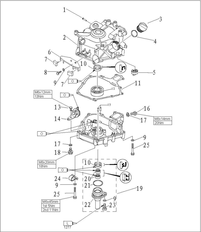
| Nr. | Reservedelsnr. | Beskrivelse | Antal | Bemærkninger |
|---|---|---|---|---|
| 15 | F15-00000013 | TAP 4x12 | ||
| 16 | GB/T5783-2000 | BOLT M8x14 | ||
| 17 | F4-04000006 | SKIVE | ||
| 18 | F4-04000001 | OLIEAFTAPNINGSBOLT M8x20 | ||
| 19 | F2.6-04060000 | OLIETÆTNINGSHUSENHED | ||
| 20 | F2.6-04060002 | Øvre olietætning til drivaksel K-5657 | ||
| 21 | F4-04060002 | Olietætningshusets O-ring | ||
| 22 | F2.6-04060001 | OLIETÆTNINGSHUS | ||
| 23 | GB/T5783-2000 | BOLT M8x20 | ||
| 24 | F25-05000013 | Klemme A | ||
| 25 | GB/T5782-2000 | BOLT M6x45 |
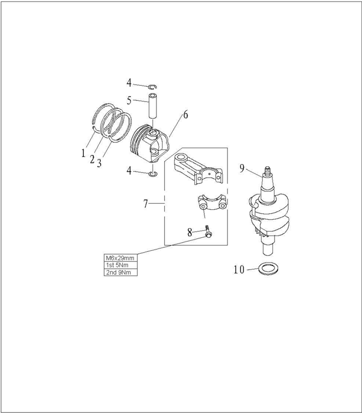
| Nr. | Reservedelsnr. | Beskrivelse | Antal | Bemærkninger |
|---|---|---|---|---|
| 1 | F2.6-04020002 | STEMPELRING1 | 1 | |
| 2 | F2.6-04020003 | STEMPELRING2 | 1 | |
| 3 | F2.6-04020004 | KOMBINERET OLIERING | 1 | |
| 4 | F2.6-04020006 | LÅSERING | 2 | |
| 5 | F2.6-04020005 | STEMPELBOLT | 1 | |
| 6 | F2.6-04020001 | STEMPEL | 1 | |
| 7 | F2.6-04020100 | PLEJLSTANG | 1 | |
| 8 | F2.6-04020103 | BOLT M6x30 | 2 | |
| 9 | F2.6-04030000 | KRUMTAPAKSELENHED | 1 | |
| 10 | F2.6-04000003 | FLADSKIVE | 1 |
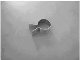
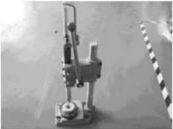
Stempelstyring
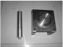
Monteringsværktøj til husets leje
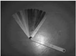
Søgerblad
Afmontering af motorenheden fra påhængsmotoren
- Åbn den øvre motorkappe.
- 2.Fjern brændstoftanken; fjern starteren.
- Fjern svinghjulsdækslet og gaskablet.
- 4.Fjern luftfilteret og karburatoren.
- Fjern boltene, som forbinder motorenheden med det øvre hus.
- 6.Løft motorenheden, og anbring den på arbejdsbordet.
Afmontering og inspektion
Cylinderdæksel
Afmontering
- 1.Fjern topstykkedækslets bolte.
- 2.Fjern cylinderdækslets bolte i omvendt rækkefølge af cylinderdækslets nummerering.
- 3.Fjern krumtaphusdækslet. Fjern ventilstødstangen.
Specialværktøj
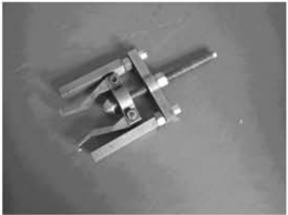
Lejeaftrækker
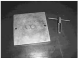
Monteringsværktøj til olietætninger
Ventilfjederkompressor
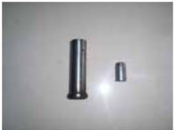
Monteringsværktøj til husets olietætning
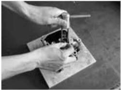
- 4.Fjern vippearmens drejepunkt, vippearmen, vippearmens aksel og stødstangspladen.
Stødstang
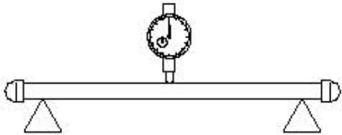
Kontrollér ventilstødstangens kast. Udskift den, hvis den angivne værdi overskrides. Grænse for ventilstødstangens kast:0.5mm
Ventil og ventilstyr
- 1.Kontrollér ventilsædets bredde. Reparer ventilsædet, hvis bredden ligger uden for det angivne område. Ventilsædebredde:0.6~0.8mm
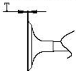
- Kontrollér ventilkantens tykkelse (T). Udskift ventilen, hvis den ikke svarer til den angivne værdi. Ventilkantens tykkelse: T
- 3.Kontrollér ventilstammens diameter. Udskift ventilen, hvis den ligger uden for det angivne område. Ventilstammens diameter:
- 4.Mål ventilstammens kast. Udskift ventilen, hvis grænsen overskrides. Grænse for ventilstammens kast:0.03mm
- 5.Mål ventilstyrets indvendige diameter.
Indsugningsventil:0.7mm
Udstødningsventil:1.0omm
Indsugningsventil:5.475~5.490mm
Udstødningsventil:5.460~5.475mm
Ventilstyrets indvendige diameter:5.500~5.512m
FORSIGTIG:
Ved udskiftning af ventilen skal der bruges et nyt ventilstyr og en ny ventilstammetætning.
Ventilfjeder
- 1.Mål ventilfjederens frie længde. Udskift den, hvis den er mindre end den angivne værdi.
- 2.Mål ventilfjederens hældning. Udskift den, hvis den angivne grænse overskrides.
Mindste frie længde: 34mm
Største hældningsgrænse: 1.2mm
- Fjern sod fra ventilen.
- Påfør et jævnt, tyndt lag mærkefarve på ventilsædets tætningsflade.
- Slib ventilen til på ventilsædet med et ventilslibeværktøj.
- Mål ventilsædets bredde.
Ventilfladen er dækket med mærkefarve.
Hvis ventilen og ventilsædet ikke passer sammen, eller ventilsædebredden ikke svarer til den angivne værdi, skal ventilsædet bearbejdes og slibes til.
Udskift ventilstyret, hvis kontaktfladen er ujævn.
Ventilsædebredde: 0.6~0.8mm
Største ventilsædebredde:1.1mm
Fræsning af ventilsæde
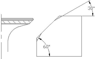
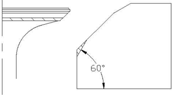
- 1.Brug en 45° ventilsædefræser til at justere ventilsædebredden. Drej fræseren med uret, indtil ventilsædets flade er glat.
- 2.Hvis ventilsædet er centreret på ventilfladen, men er for bredt, bruges en 30° fræser til at justere sædets øvre kant og en 60° fræser til at justere sædets nedre kant, så ventilsædebredden reduceres.
- Hvis ventilsædet er for smalt og ligger ved ventilfladens øvre kant, bruges en 30° fræser til at justere sædets øvre kant og om nødvendigt en 45° fræser til at justere ventilsædebredden.
Ventilvippearm
Kontrollér vippearmen for revner, gennemtæring eller skader. Udskift efter behov.
Udskiftning af ventilstyr
- 1.Slå ventilstyret ud fra forbrændingskammerets side.
- 2.Slå det nye ventilstyr ind fra toppen af cylinderdækslet.
BEMÆRK:
Påfør olie på styrets overflade før montering.
- 3.Bearbejd styrets indvendige diameter med en rival til den angivne værdi.
Ventilstyrets indvendige diameter: 5.500~5.512mm
BEMÆRK:
Når rivalen tages ud, må den ikke drejes mod uret.
Inspektion af ventilsæde
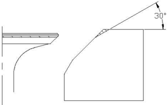
- 4.Hvis ventilens tætningsflade er for smal og ligger ved ventilfladens nedre kant, bruges en 60° fræser til at justere sædets nedre kant og om nødvendigt en 45° fræser til at justere ventilsædebredden.
- Påfør et jævnt, tyndt lag slibepasta på ventilsædet, og slib ventilen til med et slibeværktøj.
- Fjern den resterende slibepasta.
- 7.Kontrollér ventilsædebredden igen.
FORSIGTIG:
Slib ikke ventilen for meget til. Drej slibeværktøjet jævnt med en nedadrettet kraft på 40~50N. Undgå at forurene stødstangen og ventilstyret med slibepasta.
Termostat
- Fjern termostatdækslet og termostaten.
- 2.S Hæng termostaten i beholderen med vand.
- 3.Opvarm beholderen.
- 4.Kontrollér ventilløftet ved den angivne vandtemperatur. Udskift, hvis det ligger uden for specifikationen.
- 5.Monter termostaten og termostatdækslet. Spænd boltene med det angivne moment.
| Vandtemperatur | Løftehøjde |
|---|---|
| 58~62℃ | 0.05mm ventilløft |
| Over 70℃ | Over3mm |
Krumtaphus
Afmontering
- Fjern boltene i omvendt rækkefølge af krumtaphusdækslets nummerering.
- 2.Fjern krumtaphusdækslet.
- 3.Fjern knastakslen og ventilløfteren.
- Fjern plejlstangsbolten og plejlstangsdækslet, og fjern plejlstangen og stempelenheden.
- Brug en tang til at fjerne låseringen, og fjern stempelbolten og stemplet.
- 6.Fjern krumtaphuset og krumtaphuspakningen.
- 7.Fjern oliesprøjtetandhjulsenheden.
- 8.Fjern olietætningshusets bolte, og fjern olietætningshuset og olietætningen.
Stempel
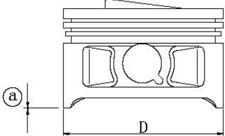
Mål stemplets udvendige diameter ved det angivne målepunkt. Udskift, hvis den ligger uden for specifikationen.
Stempeldiameter:
53.950~53.965mm
Målepunkt@: Omm
Cylinderboring
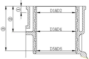
- Mål cylinderboringen særskilt ved målepunkterne ①, , ③. Mål ved hvert punkt cylinderboringen på stederne D1, D3, D5 parallelt med krumtaphuset og på stederne D2, D4, D6 vinkelret på krumtapakslen.
Målepunkthøjde:
- ②40mm;
①100mm;
③70mm
Cylinderboring:
54.00~54.015mm
Grænsemål:
54.10mm
- Beregn grænsen for konicitet og urundhed. Udskift krumtaphuset, hvis værdierne ligger uden for specifikationen.
Grænse for konicitet: 0.08mm(D1-D5, D2-D6)
Grænse for urundhed: 0.05mm(D2-D1, D6-D5)
Stempelboltens diameter
Mål stempelboltens udvendige diameter. Udskift stempelbolten, hvis den ligger uden for specifikationen.
Stempelboltens udvendige diameter:11.996~12.000mm
Stempelring
- Skub stempelringen parallelt med stemplet ind til cylinderens angivne målepunkt (1omm fra samlingsfladen).
Udskift stempelringen, hvis værdien ligger uden for specifikationen.
Øverste ring 0.15~0.30mnm/0.4mm
- Mål ringgabet med et søgerblad. Ringgab (monteret) / grænsemål:
Ring 2 0.30~0.45mm/0.6mm
Oliering 0.2~0.7mm/0.9mm
- 3.Monter stempelringen på stemplet, og mål sidespillerummet mellem stempelringen og dens rille med et søgerblad. Udskift stempelringen, hvis værdien ligger uden for specifikationen.
Sidespillerum:
Øverste ring 0.04~0.08mm
Ring 2 0.02~0.06mm
Oliering 0.06~0.16mm
Knastakslens dekompressor
- Kontrollér knastakslens dekompressor, tandhjul og vægt. Udskift tandhjulet ved slid/skader/revner. Udskift vægten, hvis den ikke bevæger sig jævnt.
- 2.Mål knastakselknastens diameter@ og højde. Udskift, hvis værdierne ligger uden for specifikationen.
Knastaksel: 26.136~26.239mm
@Knastaksel:21.950~22.050mm
- Mål knastakslens diameter. Udskift knastakslen, hvis den ligger uden for specifikationen.
Slidgrænse for knastakslens lejetap: 14.934mm
Krumtapaksel
- 1.Mål krumtapakslens plejlstangstap. Udskift, hvis den ligger uden for specifikationen.
- Mål krumtapakslens kast. Udskift, hvis det ligger uden for specifikationen.
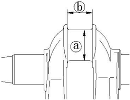
Krumtapakslens plejlstangstapdiameter @ : 23.969~23.984mm
Krumtapakslens plejlstangstapbredde : 21.0~21.1mm
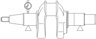
Grænse for krumtapakslens kast: 0.01mm
- Anbring et stykke plastmåletråd på plejlstangstappen parallelt med krumtapakslen.
Oliespillerum
- 2.Monter plejlstangen på plejlstangstappen.
- 3.Spænd plejlstangsboltene med det angivne moment.
Tilspændingsmoment:
Første gang
- 5Nm
Anden gang
9Nm
- 4.Fjern plejlstangen, og mål plastmåletrådens sammenpressede bredde. Udskift plejlstangen, hvis værdien ligger uden for specifikationen.
Oliespillerum: 0. 016~0. 046mm
Bemærk:
Drej ikke plejlstangen, før målingen er afsluttet.
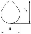
Ventilløfter
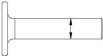
- Kontrollér ventilløfteren for slid eller skader. Udskift efter behov.
- 2.Mål ventilløfterens udvendige diameter. Udskift ventilløfteren, hvis den ligger uden for specifikationen. Ventilløfterens udvendige diameter:7.9650mm
Oliesprøjtetandhjul
Kontrollér oliesprøjtetandhjulsenheden. Udskift ved trægt løb/slid/skader/revner.
Krumtapakselleje
Kontrollér lejet. Udskift ved grubetæring eller rumlen.
BEMÆRK:
Fjern kun lejet, hvis det skal udskiftes.
Olietætningshus
- Kontrollér O-ringen for revner/skader. Udskift efter behov.
- Kontrollér olietætningshuset for revner/skader. Udskift efter behov.
Krumtaphus og krumtaphusdæksel
- Kontrollér krumtaphusdækslet. Udskift ved revner/skader.
- 2.Kontrollér kølevandskanalen for snavs eller tilstopning. Rengør efter behov.
Komplet montering
Montering af stempel og plejlstang
Monter stempel, plejlstang, stempelbolt og stempelboltens låsering.
BEMÆRK:
Sørg ved montering for, at mærket på plejlstangen er på samme side som mærket på stempelkronen.
Brug en ny låsering til stempelbolten. Sørg for, at låseringens åbning ikke flugter med åbningen i låseringsrillen.
Montering af stempelringe
- Monter olieringen, 2. ring og øverste ring.
BEMÆRK:
Sørg for, at mærket vender mod stempelkronen, når 2. ring monteres.
- Billede af stempelringgabet
Olieringens ringgab 2 (ekspanderring)
Olieringens ringgab 1 (nedre skinne)
Olieringens ringgab 3 (øvre skinne)
Ringgab 4 på stempelring 2
Øverste stempelrings ringgab 5
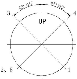

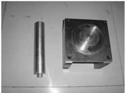
Montering af stempel
Brug stempelstyringen til at montere stemplet, og sørg for, at stempelkronens mærkning “Up” vender mod svinghjulssiden.
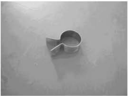
BEMÆRK:
Påfør motorolie på stemplet og stempelringens side under montering.
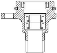
Montering af olietætningshus
- Monter olietætningerne 10.8x21x7 (2 styk) med monteringsværktøjet til olietætninger.
- Monter olietætningerne B20 X 30 X 7 med monteringsværktøjet til olietætninger.
BEMÆRK:
- ① Påfør fedt på den nye tætning før montering.
- ② Sørg for, at olietætningens fjeder vender som vist.
Montering af krumtapaksel
- Monter krumtapaksellejet i krumtaphuset med specialværktøj (hvis lejet udskiftes). Monter olietætningen.
Monteringsværktøj til husets leje
BEMÆRK:
Monter lejet med producentens mærkning vendt mod svinghjulssiden. Påfør motorolie på den nye olietætning ved montering.
- Monter krumtapakslen i krumtaphuset.
- Monter plejlstangsdækslet, og spænd plejlstangsbolten med det angivne moment. Angivet moment:12 Nm
BEMÆRK:
- 1.Monter ventilløfteren.
Påfør motorolie på bevægelige dele før montering.
Montering af knastaksel
- Monter knastakslen. Sørg for, at mærket på knastakseltandhjulet flugter med mærket på knastakslens timingtandhjul.
BEMÆRK:
Monteringsværktøj til husets olietætning
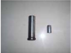
Olietætningens monteringsretning
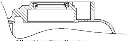
Påfør motorolie på bevægelige dele før montering.
- Monter olietætningshuset.
Montering af krumtaphusdæksel
- Monter oliesprøjtetandhjulsenheden.
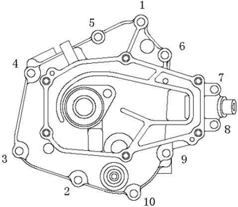
- Monter krumtaphusdækslet, og spænd boltene i to omgange som vist.
Tilspændingsmoment:
Tilspænding 1: 5Nm
Tilspænding 2: 11 Nm
BEMÆRK:
Påfør motorolie på bevægelige dele før montering.
Øvre enhed
Øvre motorkappe
Eksplosionstegning
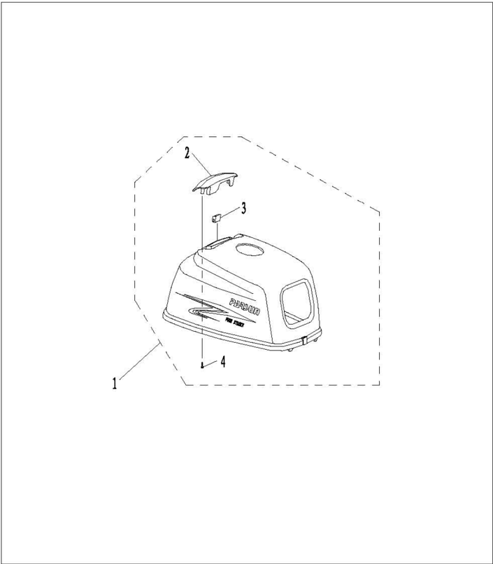
| Nr. | Reservedelsnr. | Beskrivelse | Antal | Bemærkninger |
|---|---|---|---|---|
| 1 | F2.6-06000001 | ØVRE MOTORKAPPE | 1 | |
| 2 | F2.6-06000002 | INDSUGNINGSLYDDÆMPER | 1 | |
| 3 | F2.6-06000003 | Indsugningslyddæmperens dæmper | 1 | |
| 4 | GB/T845-85 | Selvskærende skrue ST3.8x12 | 2 |
Afmontering og inspektion
- Fjern indsugningslyddæmperens bolt.
- Fjern indsugningslyddæmperen og dens dæmper.
- Kontrollér den øvre motorkappe, indsugningslyddæmperen og dens dæmper for revner eller skader. Udskift efter behov.
Nedre motorkappe
Eksplosionstegning
Afmontering og inspektion
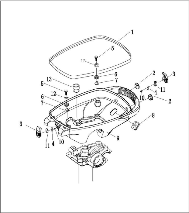
| Nr. | Reservedelsnr. | Beskrivelse | Antal | Bemærkninger |
|---|---|---|---|---|
| 1 | F2.6-05000002 | TÆTNING TIL NEDRE MOTORKAPPE | 1 | |
| 2 | F2.6-05000004 | RUND GUMMIPROP | 2 | |
| 3 | F2.6-05000008 | LÅSEKROG | 2 | |
| 4 | F2.6-05000010 | METALFORBINDELSESSTANG | 2 | |
| 5 | GB/T5783-2000 | BOLT M6X25 | 4 | |
| 6 | F2.6-05000006 | Dæmper | 4 | |
| 7 | F2.6-05000007 | Afstandsrør med flange | 4 | |
| 8 | F2.6-05000003 | FIRKANTET GUMMIPROP | 1 | |
| 9 | F2.6-05000001 | NEDRE MOTORKAPPE | 1 | |
| 10 | GB/T845-85 | Selvskærende skrue ST2.9x5 | 2 | |
| 11 | F2.6-05000009 | FORBINDELSESSTANG | 2 | |
| 12 | GB/T96-85 | Skive 6 | 4 | |
| 13 | F2.6-05000005 | Gummimuffe til olieaftapning | 1 |
- Fjern den nedre motorkappes tætning.
- Fjern den øvre motorkappes låsekrog.
- Fjern den runde gummiprop og den firkantede gummiprop.
- Kontrollér den nedre motorkappe for revner eller skader. Udskift efter behov.
- Kontrollér den øvre motorkappes låsekrog for revner eller skader. Udskift efter behov.
Styrehåndtag
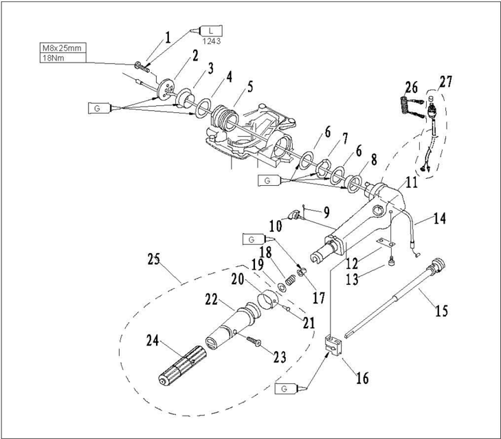
Eksplosionstegning
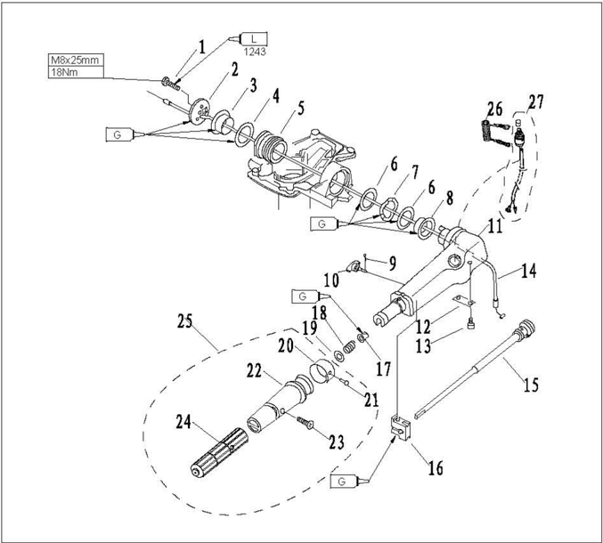
| Nr. | Reservedelsnr. | Beskrivelse | Antal | Bemærkninger |
|---|---|---|---|---|
| 1 | CB/T5783-2000 | BOLT M8x25 | ||
| 2 | F4-01000014 | STYREHÅNDTAGSDÆKSEL | ||
| 3 | F4-01000008 | HÅNDTAGSBØSNING B | ||
| 4 | F4-01000011 | BØSNINGSSKIVE A | ||
| 5 | F4-05000014 | Styrehåndtagets dæmperenhed | ||
| 6 | F4-01000010 | BØSNINGSSKIVE B | ||
| 7 | F4-01000012 | BØLGEBØSNING | ||
| 8 | F4-01000009 | HÅNDTAGSBØSNING A | ||
| 9 | CB/T91-86 | SPLIT Φ1.6x12 | ||
| 10 | F4-01090200 | FRIKTIONSJUSTERINGSBOLT |
| Nr. | Reservedelsnr. | Beskrivelse | Antal | Bemærkninger |
|---|---|---|---|---|
| 11 | F4-01090001 | Styrehåndtag | 1 | |
| 12 | F4-01090002 | Gasspjældsarmens støtte | 1 | |
| 13 | GB/T818-85 | M5x12 Skrue med panhoved | 2 | |
| 14 | F2.6-02010003 | GASKABELENHED | 1 | |
| 15 | F4-01090100 | GASARMSENHED | 1 | |
| 16 | F4-01090003 | FRIKTION | 1 | |
| 17 | F4-01090006 | BØSNING | 1 | |
| 18 | F4-01090007 | FJEDER | 1 | |
| 19 | GB/T848-85 | 10 Skive | 1 | |
| 20 | F4-01090303 | GASINDIKATOR | 1 | |
| 21 | GB/T827-86 | Φ2x5 NITTE | 1 | |
| 22 | T15-01020301 | PLASTDÆKSEL TIL HÅNDTAG | 1 | |
| 23 | GB/T820-85 | Skrue med forsænket hoved M5x24 | 1 | |
| 24 | T15-01020302 | GUMMIDÆKSEL TIL HÅNDTAG | 1 | |
| 25 | T15-01020300 | Styrehåndtagets grebsenhed | 1 | |
| 26 | F4-01090401 | Nødstopslinens enhed | 1 | |
| 27 | F2.6-02010200 | NØDSTOPKONTAKTENHED | 1 |
Afmontering og inspektion
- Fjern styrehåndtagets dæksel.
- 2.Fjern håndtagsbøsningen, bøsningsskiven og bølgeskiven.
- Fjern styrehåndtagets dæmperenhed.
- Fjern friktionsjusteringsbolten.
- Fjern styrehåndtaget.
- Fjern gaskablet.
- Fjern gasspjældsarmens støtte og gasspjældsarmen.
- Fjern nødstopkontakten.
- Kontrollér styrehåndtaget for revner eller skader. Udskift efter behov.
- a e efter behov.
- Kontrollér styrehåndtagets dæmper for revner eller skader. Udskift efter behov.
- Kontrollér gaskablet for revner eller skader. Udskift efter behov.
- Kontrollér nødstopkontaktens elektriske gennemgang. Udskift, hvis den ikke svarer til specifikationen.
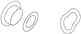
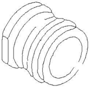
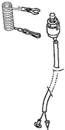
Fjern låsepladen:
Ledende
Monter låsepladen:
Ikke-ledende
Tryk på nødstopkontaktens knap: Ledende
Beslag
Eksplosionstegning
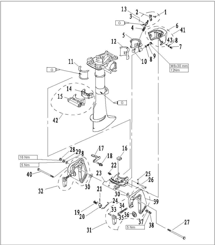
| Nr. | Reservedelsnr. | Beskrivelse | Antal | Bemærkninger |
|---|---|---|---|---|
| 1 | CB/T875-86 | NITTE 4x11 | 1 | |
| 2 | F4-01060002 | KLEMMEHÅNDTAG | 1 | |
| 3 | F2.6-01050101 | LÅSESKRUE | 1 | |
| 4 | F2.6-01050002 | FJEDER | 1 | |
| 5 | F2.6-01050001 | DREJEBESLAGSDÆKSEL | 1 | |
| 6 | F2.6-00000101 | BESLAGSDÆKSEL | 1 | |
| 7 | CB/T818-2000 | SKRUE MED PANHOVED M6x16 | 2 | |
| 8 | CB/T97.1-85 | SKIVE 6 | 6 | |
| 9 | CB/T5783-2000 | BOLT M6x30 | 4 | |
| 10 | F2.6-01050200 | LÅSEBLOKENHED | 1 | |
| 11 | F2.6-01000003 | BØSNING A | 1 | |
| 12 | F2.6-01000004 | BØSNING B | 1 | |
| 13 | F2.6-01050100 | LÅSEHÅNDTAGSENHED | 1 | |
| 14 | F2.6-01040100 | DÆMPER | 1 |
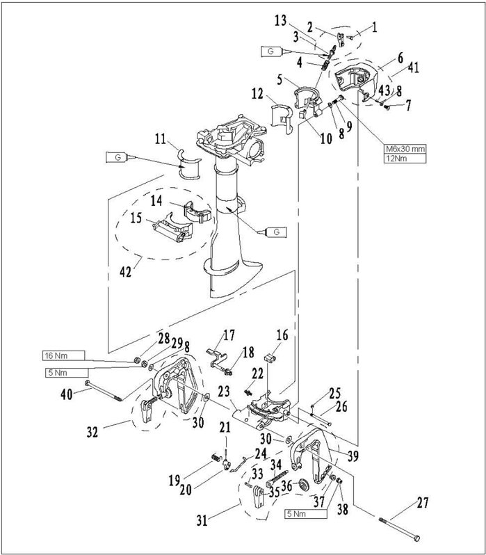
| Nr. | Reservedelsnr. | Beskrivelse | Antal | Bemærkninger |
|---|---|---|---|---|
| 15 | F2.6-01040001 | TRYKOPTAGELSESBESLAG | 1 | |
| 16 | F2.6-01030007 | ARM | 1 | |
| 17 | F2.6-01030100 | TILTKLEMMEHÅNDTAGSENHED | 1 | |
| 18 | F4-01090006 | BØSNING | 1 | |
| 19 | F2.6-01030003 | FJEDER | 1 | |
| 20 | F2.6-01030004 | TILTLÅSEARM | 1 | |
| 21 | CB/T879.2-200 | 2x10TAP | 1 | |
| 22 | GB/T7940.1-95 | SMØRENIPPEL M6 | 1 | |
| 23 | F2.6-01030001 | DREJEBESLAG | 1 | |
| 24 | F2.6-01030005 | TILTLÅSESTANG | 1 | |
| 25 | GB/T896-86 | CLIPS 3.5 | 1 | |
| 26 | F2.6-01030006 | TAP | 1 | |
| 27 | F2.6-01000001 | BOLT M8x135 | 1 | |
| 28 | CB/T6172.1-85 | MØTRIK M8 | 1 |
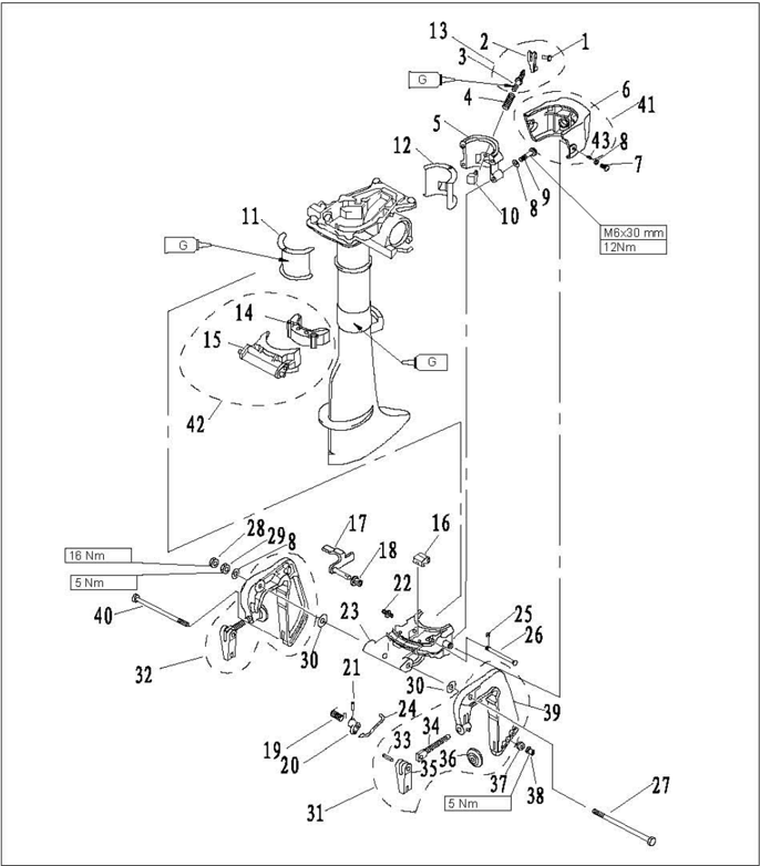
| Nr. | Reservedelsnr. | Beskrivelse | Antal | Bemærkninger |
|---|---|---|---|---|
| 29 | CB/T6170-85 | MØTRIK M8 | 1 | |
| 30 | CB/T96-1985 | SKIVE 8 | 2 | |
| 31 | F2.6-01010000 | VENSTRE BESLAGSENHED | 1 | |
| 32 | F2.6-01020000 | HØJRE BESLAGSENHED | 1 | |
| 33 | F4-01010005 | NITTE | 2 | |
| 34 | F4-01010002 | KLEMMEBOLT | 2 | |
| 35 | F4-01010004 | HÅNDTAG TIL AGTERSPEJLSKLEMME | 2 | |
| 36 | F4-01010003 | KLEMMEPLADE | 2 | |
| 37 | F2.6-01000002 | BOLTBØSNING | 1 | |
| 38 | GB/T889.1-2000 | M6MØTRIK | 1 | |
| 39 | F2.6-01010001 | KLEMMEBESLAG (VENSTRE) | 1 | |
| 40 | CB/T5782-2000 | BOLT M6x125 | 1 | |
| 41 | F2.6-00000100 | BESLAGSDÆKSELENHED | 1 | |
| 42 | F2.6-01040000 | TRYKOPTAGELSESENHED | 1 | |
| 43 | F2.6-00000102 | BØSNING | 1 |
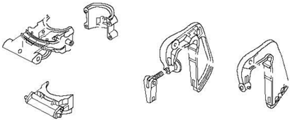
Afmontering og inspektion
- 1.Fjern klemmehåndtaget og beslagets dæksel.
- 2.Fjern drejebeslagets dæksel.
- 3.Fjern drejebeslagets bøsning og dæmper.
- 4.Fjern klemmebeslaget.
- 5.Fjern drejebeslaget.
- 6.Fjern tiltklemmehåndtaget og tiltlåsearmen.
- Kontrollér drejebeslaget og klemmebeslaget for skader eller revner. Udskift efter behov.
- Kontrollér drejebeslagets bøsning og dæmper for skader eller revner. Udskift efter behov.
- Kontrollér tiltklemmehåndtaget og tiltlåsearmen for deformation eller skader. Udskift efter behov.


Eksplosionstegning af øvre enhed
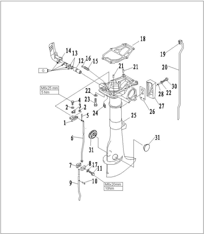
| Nr. | Reservedelsnr. | Beskrivelse | Antal | Bemærkninger |
|---|---|---|---|---|
| 1 | F2.6-02000006 | GEARSKIFTESTANGSARM | 1 | |
| 2 | GB/T97.1-85 | SKIVE 5 | 3 | |
| 3 | F2. 6-02000008 | GEARSKIFTESTANGSARMENS SKIVE | ||
| 4 | GB/T5783-2000 | BOLT M5x12 | 1 | |
| 5 | GB/T91-86 | SPLIT 1.6x12 | 1 | |
| 6 | F2.6-02000007 | GEARSKIFTESTANG | 1 | |
| 7 | F2.6-00000001 | GEARSKIFTESTANGSFORBINDELSE A | 1 | |
| 8 | F2.6-00000002 | GEARSKIFTESTANGSFORBINDELSE B | ||
| 9 | F2.6-03000005 | GEARSKIFTEKNASTAKSEL | 1 | |
| 10 | GB/T879.2-2000 | 2.5x14TAP | 1 | |
| 11 | GB/T5783-2000 | BOLT M6x20 | 1 | |
| 12 | F4-02000002 | Gearskiftestangsarmens bøsning | 1 | |
| 13 | JISB2401 | O-ring P9 | 2 | |
| 14 | F2.6-02020000 | GEARSKIFTEHÅNDTAGSENHED | 1 |
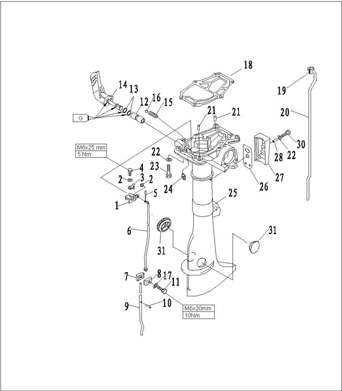
| Nr. | Reservedelsnr. | Beskrivelse | Antal | Bemærkninger |
|---|---|---|---|---|
| 15 | F4-02000003 | GEARFJEDER | 1 | |
| 16 | GB308-84 | Stålkugle 8 | 1 | |
| 17 | F4-00000005 | SKIVE | 1 | |
| 18 | F2.6-00000003 | MOTORPAKNING | 1 | |
| 19 | F4-02040002 | I-FORMET GUMMIBÅND | 1 | |
| 20 | F2.6-02000003 | VANDRØR | 1 | |
| 21 | F15-0000013 | TAP 4x12 | 2 | |
| 22 | CB/T97.1-85 | SKIVE 6 | 7 | |
| 23 | CB/T5783-2000 | BOLT M6x35 | 6 | |
| 24 | CB/T7940.1-95 | SMØREKOP M6 | 1 | |
| 25 | F2.6-02000001 | ØVRE HUS | 1 | |
| 26 | F2.6-02000005 | UDSTØDNINGSDÆKSELPAKNING | 1 | |
| 27 | F2.6-02000004 | UDSTØDNINGSDÆKSEL | 1 | |
| 28 | F2.6-00000102 | BØSNING | 1 |
Afmontering og inspektion
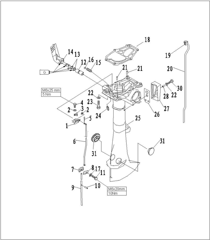
| Nr. | Reservedelsnr. | Beskrivelse | Antal | Bemærkninger |
|---|---|---|---|---|
| 29 | CB/T818-2000 | Skrue med panhoved M6x16 | ||
| 30 | F4-02000012 | ØVRE GUMMIPROP | 2 |
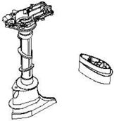
- 1.Fjern vandrøret.
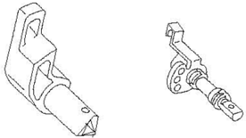
- 2.Fjern gearskiftehåndtaget.
- 3.Fjern gearskiftestangen og gearskiftestangens arm.
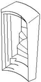
- 4.Fjern udstødningsdækslet.
- Kontrollér det øvre hus for revner eller slid. Udskift efter behov.
- 6.Kontrollér gearskiftehåndtaget for slid eller skader. Udskift efter behov.
- 7.Kontrollér udstødningsdækslet for revner eller slid. Udskift efter behov.
Underenhed
Vandpumpeenhed
Eksplosionstegning
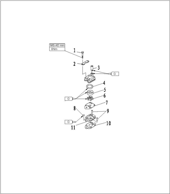
| Nr. | Reservedelsnr. | Beskrivelse | Antal | Bemærkninger |
|---|---|---|---|---|
| 1 | CB/T5783-2000 | BOLT M6x40 | 4 | |
| 2 | F2.6-03000016 | VANDPUMPENS FASTGØRELSESPLADE | 2 | |
| 3 | F4-03000021 | VANDPUMPENS GUMMIRØR | 1 | |
| 4 | JASO 19-033 | O-ring | 1 | |
| 5 | F2.6-03000015 | VANDPUMPENS INDVENDIGE HUS | 1 | |
| 6 | F2.6-03000100 | IMPELLERENHED | ||
| 7 | F2.6-03000010 | YDERPLADE | 1 | |
| 8 | F2.6-03000009 | O-ring | 1 | |
| 9 | F4-03000013 | TAP Φ4x18 | 2 | |
| 10 | F2.6-03000007 | VANDPUMPEPAKNING | 1 | |
| 11 | F2.6-03000008 | VANDPUMPEHUS | 1 |
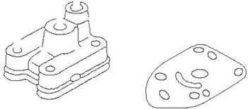
Afmontering og inspektion
- Fjern vandpumpens fastgørelsesplade.
- Fjern vandpumpehuset.
- Fjern impelleren, det indvendige hus og O-ringen til vandpumpens indvendige hus.
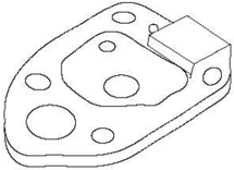
- Fjern vandpumpens bund.
- Kontrollér vandpumpehuset og yderpladen for revner, deformation eller skader. Udskift efter behov.
- Kontrollér vandpumpens indvendige hus og impelleren for revner, deformation, forbrænding eller skader. Udskift efter behov.
- 7.Kontrollér vandpumpens bund for revner, deformation, ridser eller skader. Udskift efter behov.

Eksplosionstegning af underenhed
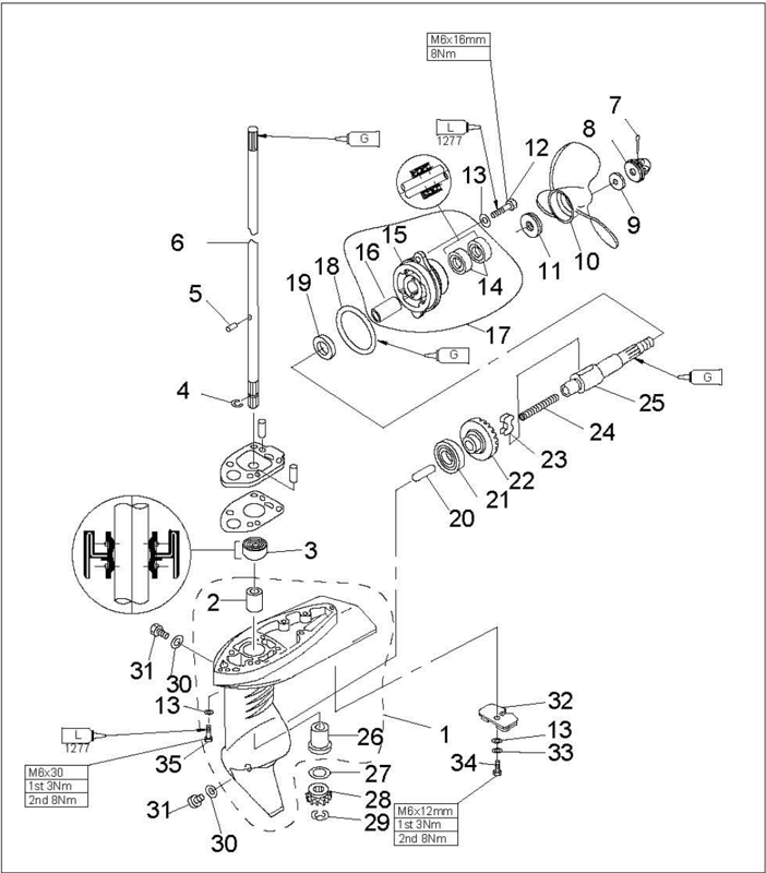
| Nr. | Reservedelsnr. | Beskrivelse | Antal | Bemærkninger |
|---|---|---|---|---|
| 1 | F2.6-03000001 | GEARHUS | 1 | |
| 2 | F2.6-03000003 | LEJE | 1 | |
| 3 | F2.6-03000004 | OLIETÆTNING 9.8x24x9 | 1 | |
| 4 | F2.6-03000012 | CLIPS | 1 | |
| 5 | F2.6-03000013 | TAP Φ3.5x7 | 1 | |
| 6 | F2.6-03000011 | DRIVAKSEL | 1 | |
| 7 | GB/T91-86 | SPLIT 2.5x30 | 1 | |
| 8 | F4-03080000 | MØTRIKENHED | 1 | |
| 9 | F4-03000026 | SKIVE | 1 | |
| 10 | F2.6-03010000 | PROPELENHED | 1 | |
| 11 | F4-03000025 | AFSTANDSSTYKKE | 1 | |
| 12 | GB/T5783-2000 | Bolt M6x16 | 2 | |
| 13 | GB/T97.1-85 | SKIVE 6 | 2 | |
| 14 | F4-03050002 | OLIETÆTNING 13x22x7 | 2 |
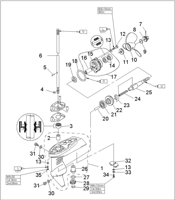
| Nr. | Reservedelsnr. | Beskrivelse | Antal | Bemærkninger |
|---|---|---|---|---|
| 15 | F2.6-03000301 | GEARHUSDÆKSEL | 1 | |
| 16 | F2.6-03000302 | BØSNING | 1 | |
| 17 | F2.6-03000300 | GEARHUSDÆKSELENHED | 1 | |
| 18 | JISB2401 P48 | O-ring Φ47.1x3.5 | 1 | |
| 19 | F2.6-03000021 | SKIVE | 1 | |
| 20 | F2.6-03000020 | GEARSKIFTEPROP | 1 | |
| 21 | NTN6003EY | KUGLELEJE | 1 | |
| 22 | F2.6-03000019 | FREMGEARENHED | 1 | |
| 23 | F2.6-03000202 | KLOKOBLING | 1 | |
| 24 | F4-03030003 | KLOKOBLINGSFJEDER | 1 | |
| 25 | F2.6-030000201 | PROPELAKSEL | 1 | |
| 26 | F2.6-03000002 | LEJE | 1 | |
| 27 | F2.6-03000017 | Justeringsskive (T: 2.0 mm) | 1 | |
| 28 | F2.6-03000018 | DRIVTANDHJUL | 1 |
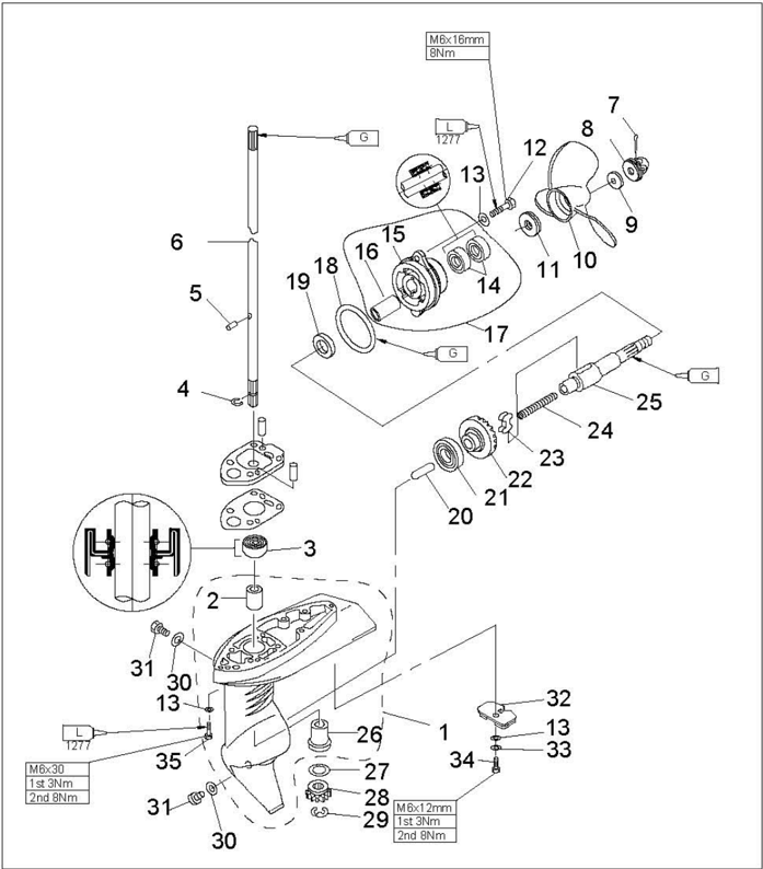
| Nr. | Reservedelsnr. | Beskrivelse | Antal | Bemærkninger |
|---|---|---|---|---|
| 29 | CB/T896-86 | LÅSERING 6 | ||
| 30 | F4-03000024 | PAKNING | ||
| 31 | F4-03000023 | PROP TIL OLIEHUL | ||
| 32 | F4-03000022 | ANODE | ||
| 33 | CB/T861.1-87 | INDVENDIGT FORTANDET SKIVE 6 | ||
| 34 | CB/T5783-2000 | BOLT M6x12 | ||
| 35 | CB/T5783-2000 | Bolt M6x30 |
Afmontering og inspektion
- Fjern splitten, møtrikenheden og afstandsstykket.
- 2.Fjern propelenheden og afstandsstykket.
- 3.Fjern gearhusdækslet.
- Fjern drivakslen, fremgear-enheden og gearskifteproppen.
- 5.Fjern gearskiftestangens knastenhed og drivakslen.
- Fjern bøsningen med beskyttelsesplade.
- Fjern bøsningen uden beskyttelsesplade med monteringsværktøjet til bøsninger.
- 8.Fjern klokoblingen fra propelakslen.
Propelaksel og klokobling
- Kontrollér klokoblingen for slid eller skader. Udskift efter behov.
- Kontrollér propelakslen for slid eller skader. Udskift efter behov.
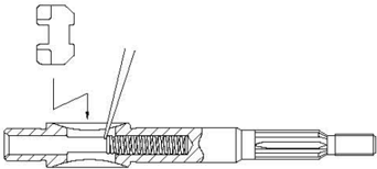
Montering af klokobling
- Anbring klokoblingens fjeder i hullet i propelakslens ende.
- 2.Monter klokoblingen som vist. Vær opmærksom på retningen.
Gearhusdæksel
- Kontrollér lejet for rust eller rumlen under drift. Udskift efter behov.
- Fjern leje og olietætning med en lejeaftrækker.
Bemærk:
Fjern kun lejet, hvis det skal udskiftes.
- Rengør husdækslet med en blød børste og opløsningsmiddel.
- Kontrollér husdækslet for revner eller skader. Udskift efter behov.
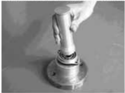
Monter olietætningen.
Bemærk:
Brug specialværktøj til at montere olietætningen og lejet.
Bøsning
Drivaksel
Kontrollér drivakslen for deformation eller slid. Udskift efter behov.
Tandhjul
Leje til fremgear
Kontrollér lejet for rust og rumlen ved rotation. Udskift efter behov.
Gearhus
- Kontrollér gearhusdækslet for revner eller skader. Kontrollér, om kølevandsindtaget er tilstoppet. Udskift efter behov.
- værktøj.
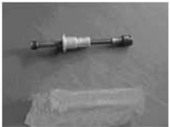
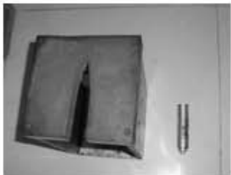
Monteringsværktøj til bøsning med beskyttelsesplade
Gearhusstøtte og monteringsværktøj til bøsning uden beskyttelsesplade
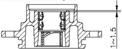
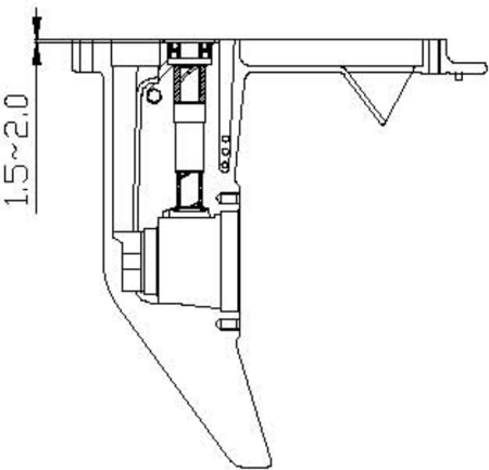
- 3.Monter en ny olietætning med den viste dybde. (enhed: mm)
Kontrollér bøsningen med beskyttelsesplade og bøsningen uden beskyttelsesplade for slid, revner eller skader. Udskift efter behov.

Montering af olietætning og leje i gearhusdækslet

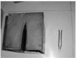
Gearhusstøtte og monteringsværktøj til drivakslens olietætning
Almindelige problemer og løsninger
| Fejltype | Mulig årsag | Afhjælpning |
|---|---|---|
| Starteren fungerer ikke | Starterens komponenter er defekte | Reparer eller udskift |
| Motoren starter ikke (starteren fungerer) | Brændstoftanken er tom. Brændstoffet er forurenet eller gammelt | Fyld tanken med rent, frisk brændstof |
| Motoren starter ikke (starteren fungerer) | Udluftningsskruen er ikke løsnet | Løsn udluftningsskruen |
| Motoren starter ikke (starteren fungerer) | Tændrør tilsmudsede eller af forkert type. | Kontrollér tændrør. Rengør eller udskift med den anbefalede type |
| Motoren starter ikke (starteren fungerer) | Tændrørshætte(r) monteret forkert | Kontrollér og genmonter hætte(r) |
| Motoren starter ikke (starteren fungerer) | Tændingsledningerne er beskadigede eller dårligt tilsluttet | Kontrollér ledningerne for slid eller brud. Spænd alle løse forbindelser. Udskift slidte eller brudte ledninger |
| Motoren starter ikke (starteren fungerer) | Tændingsdelene er defekte | Udskift |
| Motoren starter ikke (starteren fungerer) | Nødstopkontaktens line er ikke fastgjort | Fastgør nødstopslinen |
| Motoren starter ikke (starteren fungerer) | Motorens indvendige dele er beskadigede | Reparer |
| Motoren starter ikke (starteren fungerer) | Ventilspillerummet er forkert | Kontrollér og justér som angivet |
| Motoren går ujævnt i tomgang eller går i stå | Tændrør tilsmudsede eller af forkert type. | Kontrollér tændrør. Rengør eller udskift med den anbefalede type |
| Motoren går ujævnt i tomgang eller går i stå | Brændstofsystemet er tilstoppet | Kontrollér for klemt eller bøjet brændstofslange eller andre blokeringer i brændstofsystemet |
| Motoren går ujævnt i tomgang eller går i stå | Brændstoffet er forurenet eller gammelt | Fyld tanken med rent, frisk brændstof |
| Motoren går ujævnt i tomgang eller går i stå | Tændrørsgabet er forkert | Kontrollér og justér som angivet |
| Motoren går ujævnt i tomgang eller går i stå | Tændingsledningerne er beskadigede eller dårligt tilsluttet | Kontrollér ledningerne for slid eller brud. Spænd alle løse forbindelser. Udskift slidte eller brudte ledninger |
| Motoren går ujævnt i tomgang eller går i stå | Den angivne motorolie anvendes ikke | Kontrollér og udskift olien som angivet |
| Motoren går ujævnt i tomgang eller går i stå | Termostaten er defekt eller tilstoppet | Udskift |
| Motoren går ujævnt i tomgang eller går i stå | Karburatorens justeringer er forkerte | Udskift |
| Motoren går ujævnt i tomgang eller går i stå | Brændstoftankens udluftningsskrue er lukket | Løsn udluftningsskruen |
| Motoren går ujævnt i tomgang eller går i stå | Gaskablets justering er forkert | Justér korrekt |
| Motoren går ujævnt i tomgang eller går i stå | Chokerknappen er trukket ud | Før tilbage til udgangspositionen |
| Motoren går ujævnt i tomgang eller går i stå | Motorvinklen er for stor | Før tilbage til normal driftsposition |
| Motoren mister effekt | Propellen er beskadiget | Reparer eller udskift propellen |
| Motoren mister effekt | Trimvinklen er forkert | Justér trimvinklen for at opnå den mest effektive drift |
| Motoren mister effekt | Motoren er monteret i forkert højde på agterspejlet | Justér motoren til den korrekte højde på agterspejlet |
| Motoren mister effekt | Bådbunden er tilgroet med marine organismer | Rengør bådbunden |
| Motoren mister effekt | Tang eller andre fremmedlegemer er viklet omkring gearhuset | Fjern fremmedlegemer, og rengør underenheden |
| Motoren mister effekt | Brændstofsystemet er tilstoppet | Kontrollér for klemt eller bøjet brændstofslange eller andre blokeringer i brændstofsystemet |
| Motoren mister effekt | Brændstoffet er forurenet eller gammelt | Fyld tanken med rent, frisk brændstof |
| Motoren mister effekt | Tændrørsgabet er forkert | Kontrollér og justér som angivet |
| Motoren mister effekt | Tændingsledningerne er beskadigede eller dårligt tilsluttet | Kontrollér ledningerne for slid eller brud. Spænd alle løse forbindelser. Udskift slidte eller brudte ledninger |
| Motoren mister effekt | Tændingsdelene har svigtet | Udskift |
| Motoren mister effekt | Den angivne motorolie anvendes ikke, eller der er påfyldt for meget olie | Kontrollér og udskift olien som angivet, eller justér motoroliestanden til det angivne niveau |
| Motoren mister effekt | Termostaten er defekt | Udskift |
| Motoren mister effekt | Brændstofsamlingen er forkert tilsluttet | Tilslut korrekt |
| Motoren mister effekt | De angivne tændrør anvendes ikke | Kontrollér og udskift tændrør som angivet |
| Motoren vibrerer for meget | Propellen er beskadiget | Reparer eller udskift propellen |
| Motoren vibrerer for meget | Propelakslen er beskadiget | Udskift |
| Motoren vibrerer for meget | Tang eller andre fremmedlegemer er viklet omkring propellen | Fjern fremmedlegemer, og rengør propellen |
| Motoren vibrerer for meget | Motorens monteringsbolt er løs | Spænd bolten |
| Motoren vibrerer for meget | Styredrejepunktet er løst | Spænd styredrejepunktet |
| Motoren vibrerer for meget | Styredrejepunktet er beskadiget | Udskift |